

schooner
-
Posts
723 -
Joined
-
Last visited
Content Type
Profiles
Forums
Gallery
Events
Posts posted by schooner
-
-
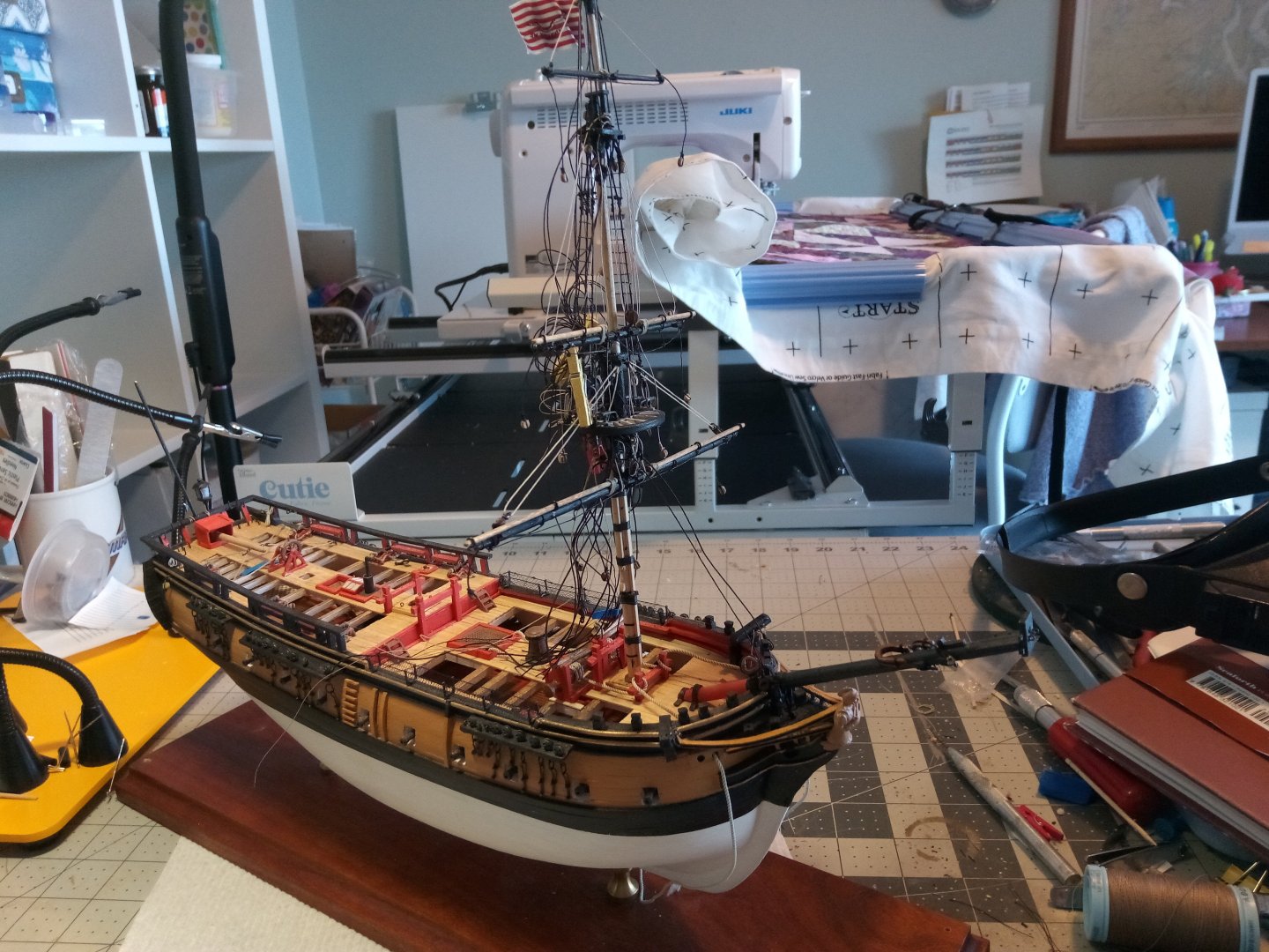
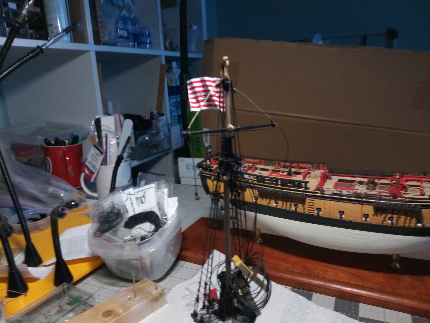
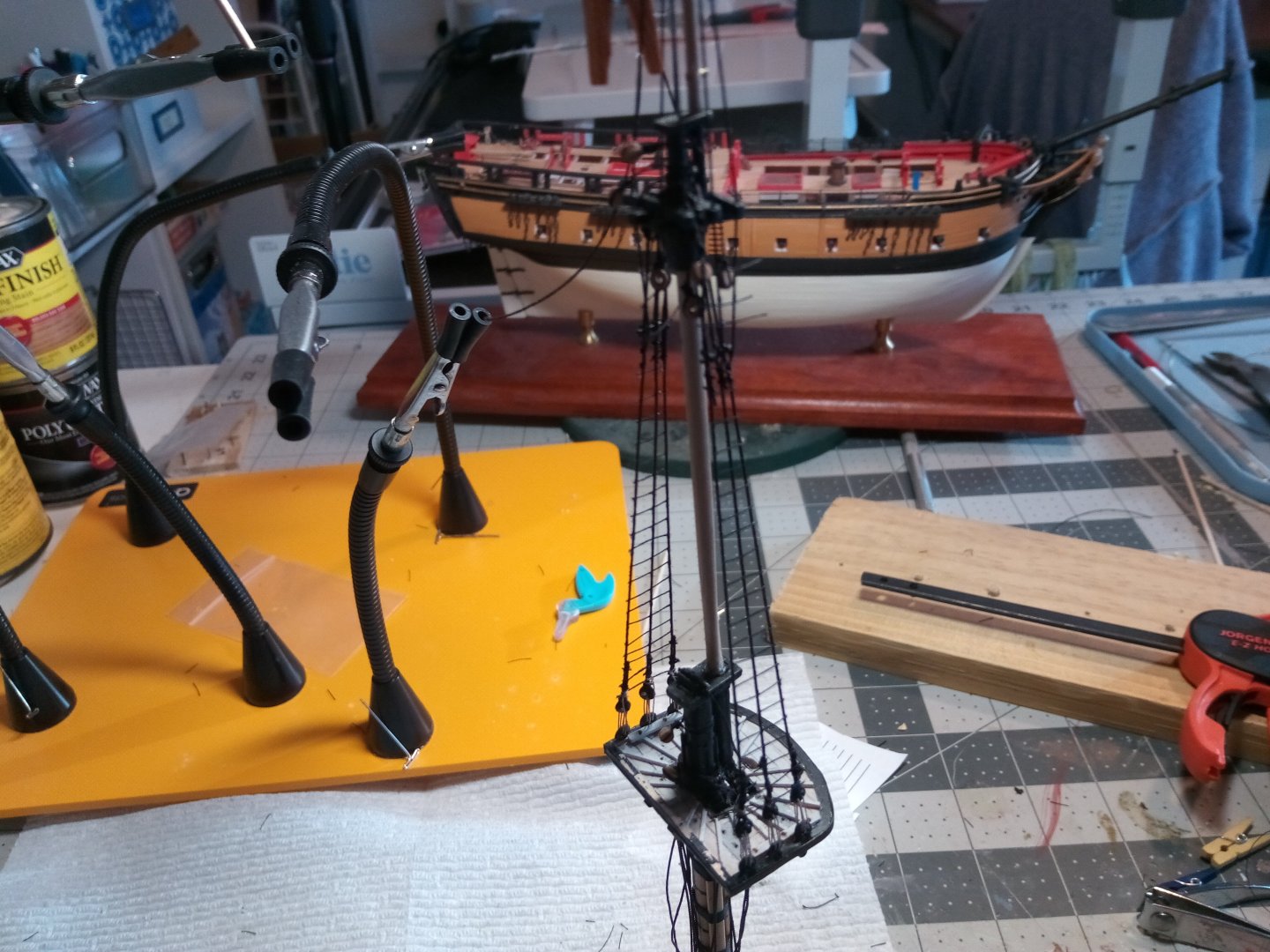
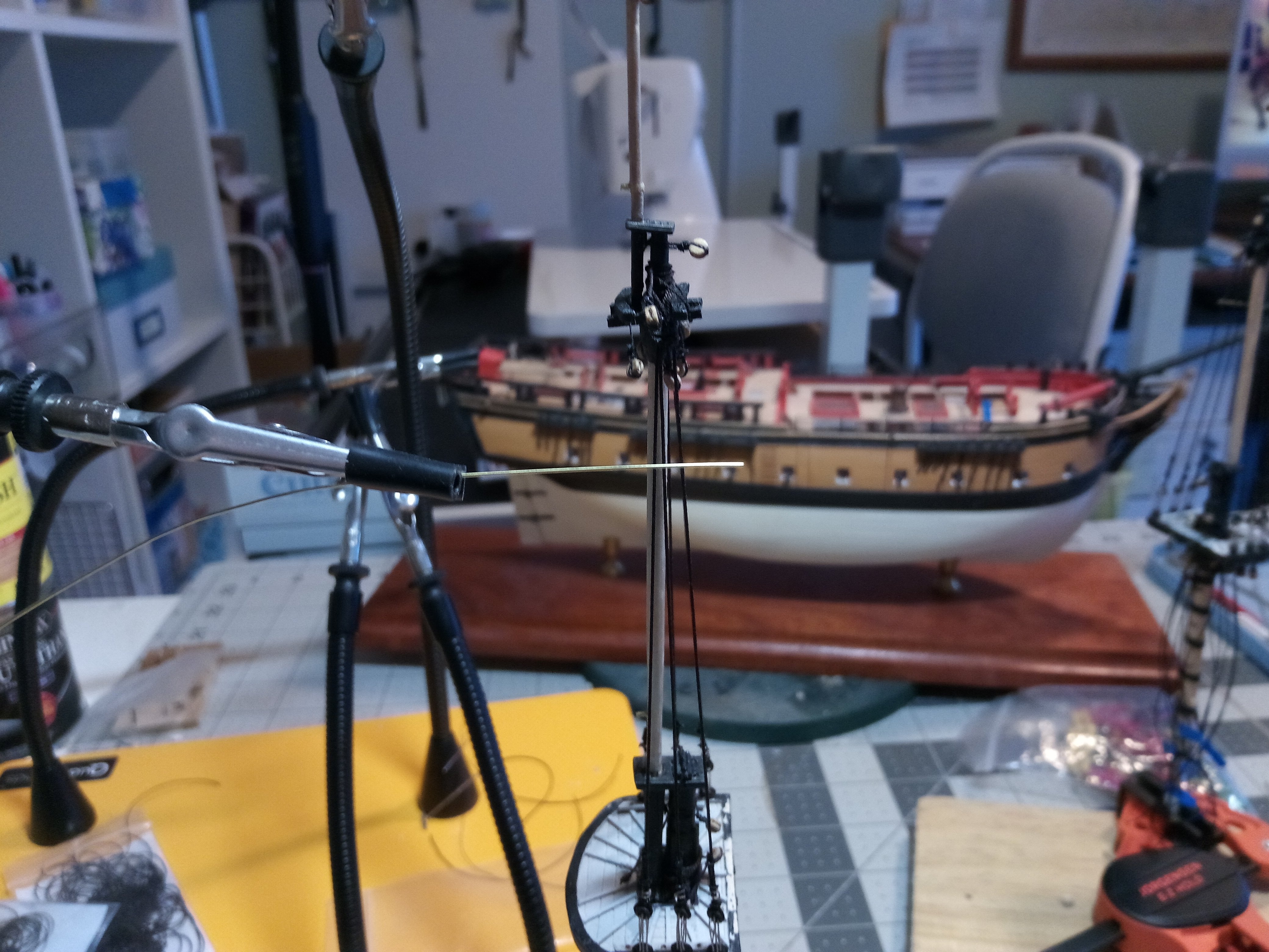
Main mast in place
The main mast has been stepped and the forestays are in place:

The deadeyes have been attached to the shrouds and backstays and the main yard jeers and truss pendants have been rigged to their tackles around the base of the mast:
Next up will be stepping the Mizzen.
- Mr Whippy, whitejamest and KurtH
-
 3
3
-
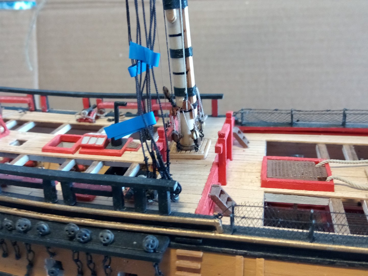
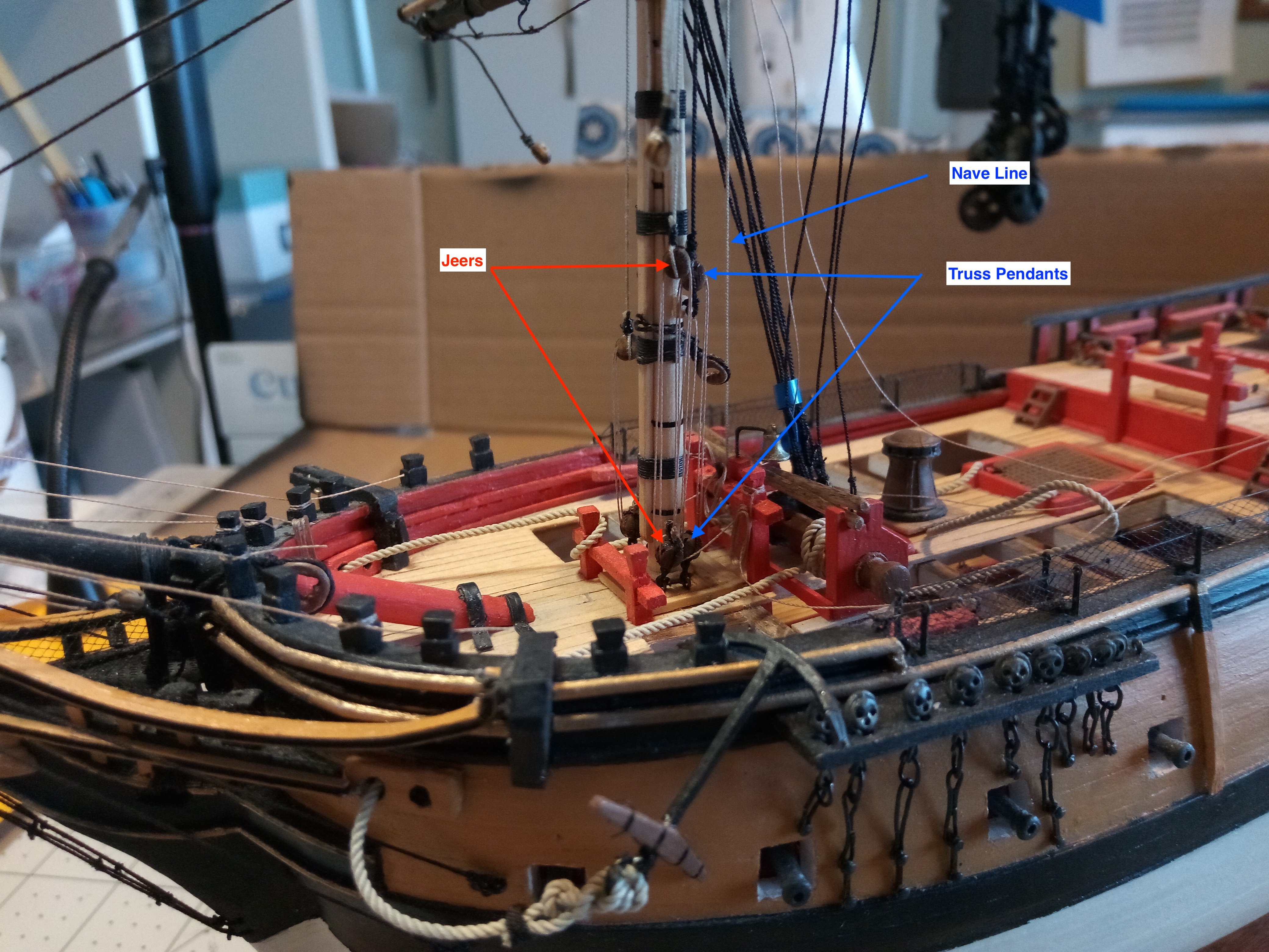
The lines that come down the foremast and are belayed around the mast base are in place. Both the Truss pendants and the Jeers terminate in tackles made up of 2 double blocks (there are 2 more sets on the far side of the mast). The Nave line is just belayed to a pin rack:

The upper deadeyes have been added to the shrouds and backstays:
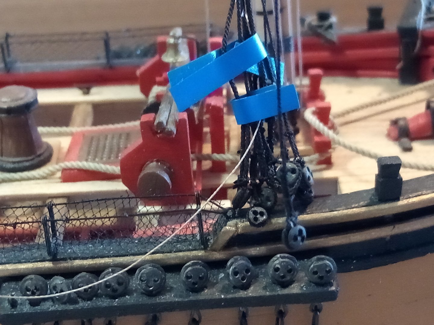
Rigging the anchors was made a little easier by the rigging hooks available from the syrenshipmodelcompany.com I used them on the bottom of the rigging tackles shown in the first photo and they should come in very handy for rigging the futtock shrouds under the tops:
And here is the anchor in place:
I have to make up some rope coils (one of the most tedious tasks for me) and then it will be time to step the main mast.
-
VERY nice!!
I've got the SYREN on my to do list - if mine turns out anywhere near what your's looks like I'll be happy.
-
-
Great looking model! Your weathering looks realistic but not overdone.
- Old Collingwood and Canute
-
2
-
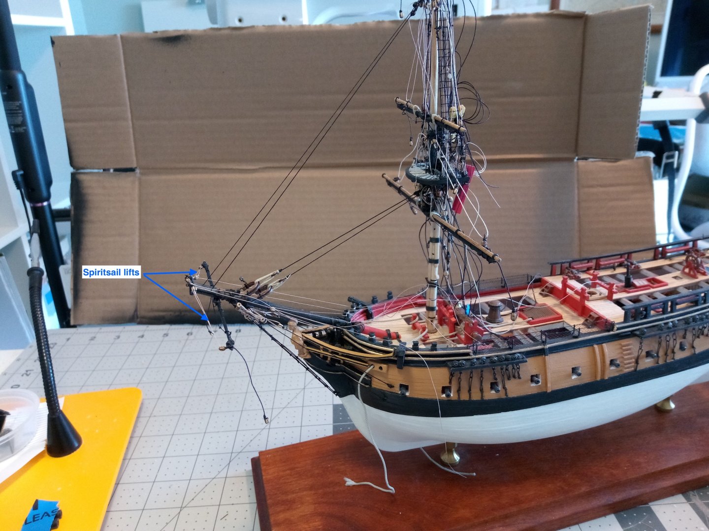
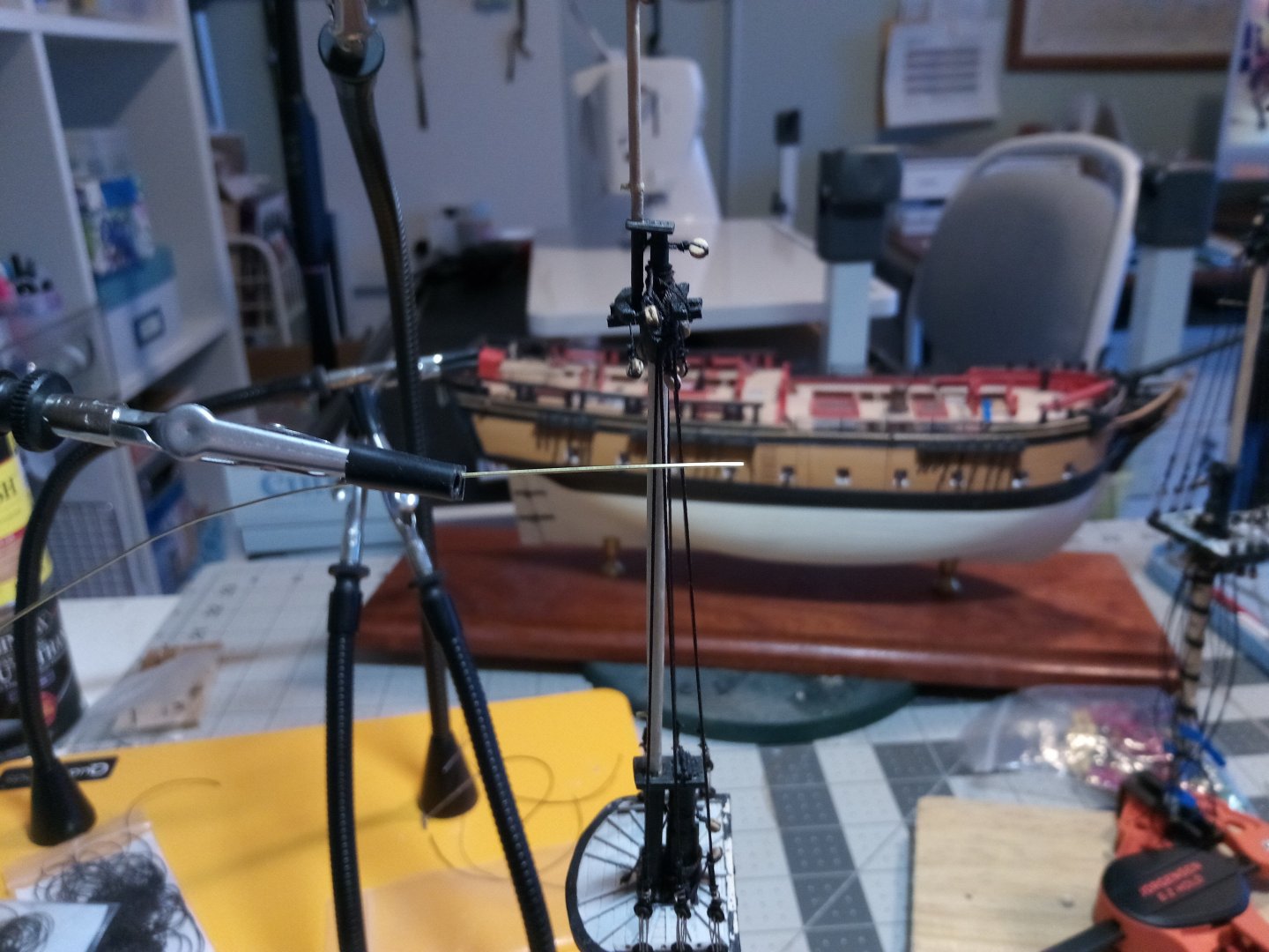
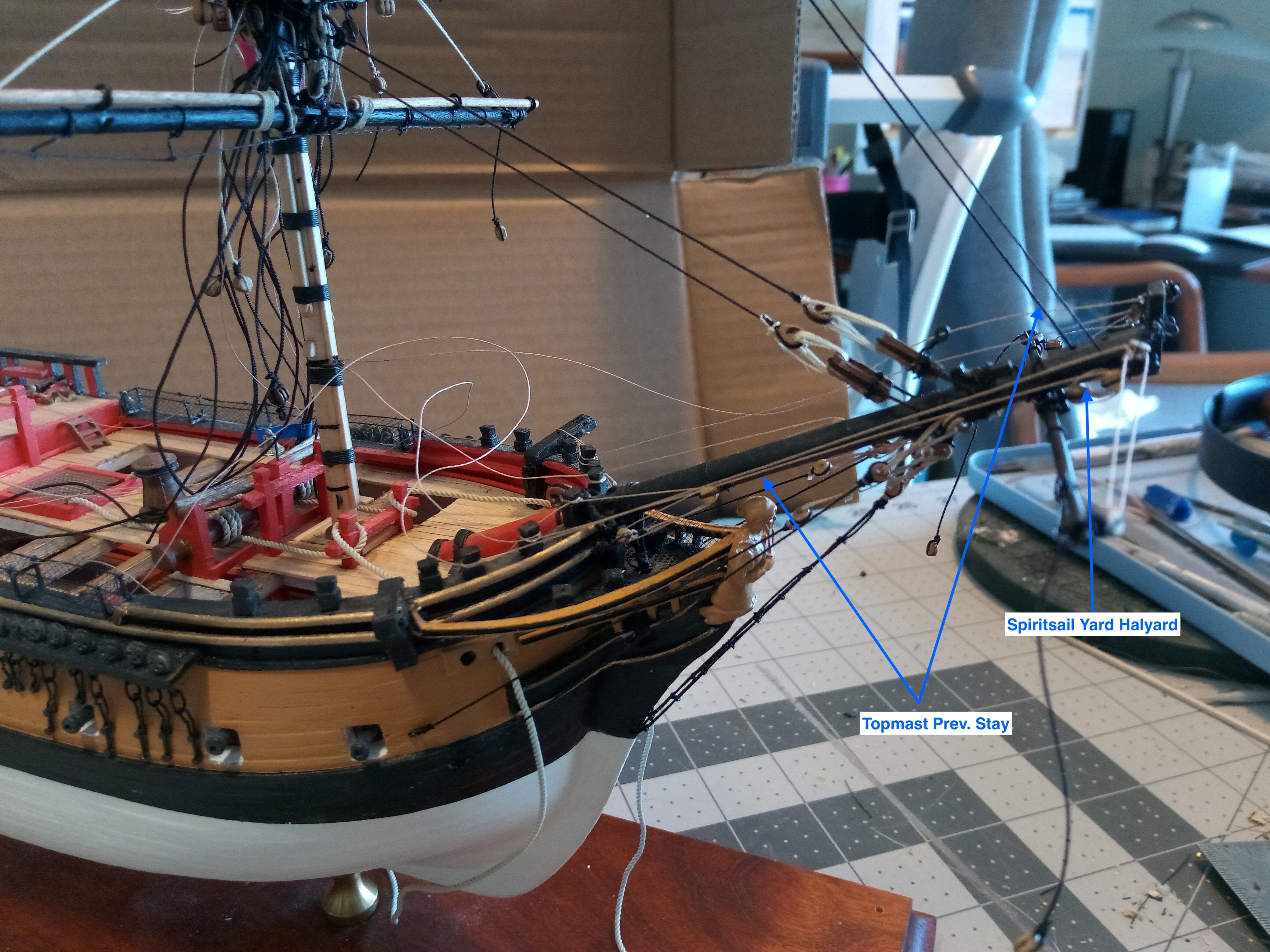
Rigging around the Bowsprit
The Spiritsail yard has been rigged with blocks for the lifts and the halyard, eyebolts for the guys and a brass rod to secure it to the underside of the bowsprit:

The following photos show the standing and running rigging that has been attached:

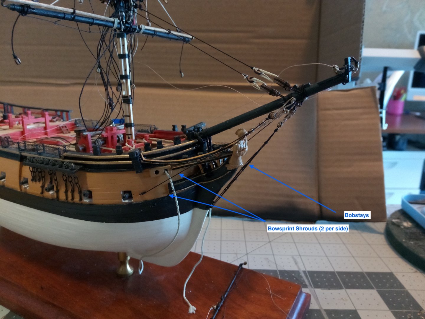

This is as far as I can go in this area without rigging the jib boom. The boom is very fragile and I know that if I rig it now I will end up snapping it off as I turn the hull back and forth while doing the mast rigging so I will hold off adding the boom until all the other rigging is done.
Next I’ll start with adding the deadeyes for the lower shrouds on the Foremast.
-
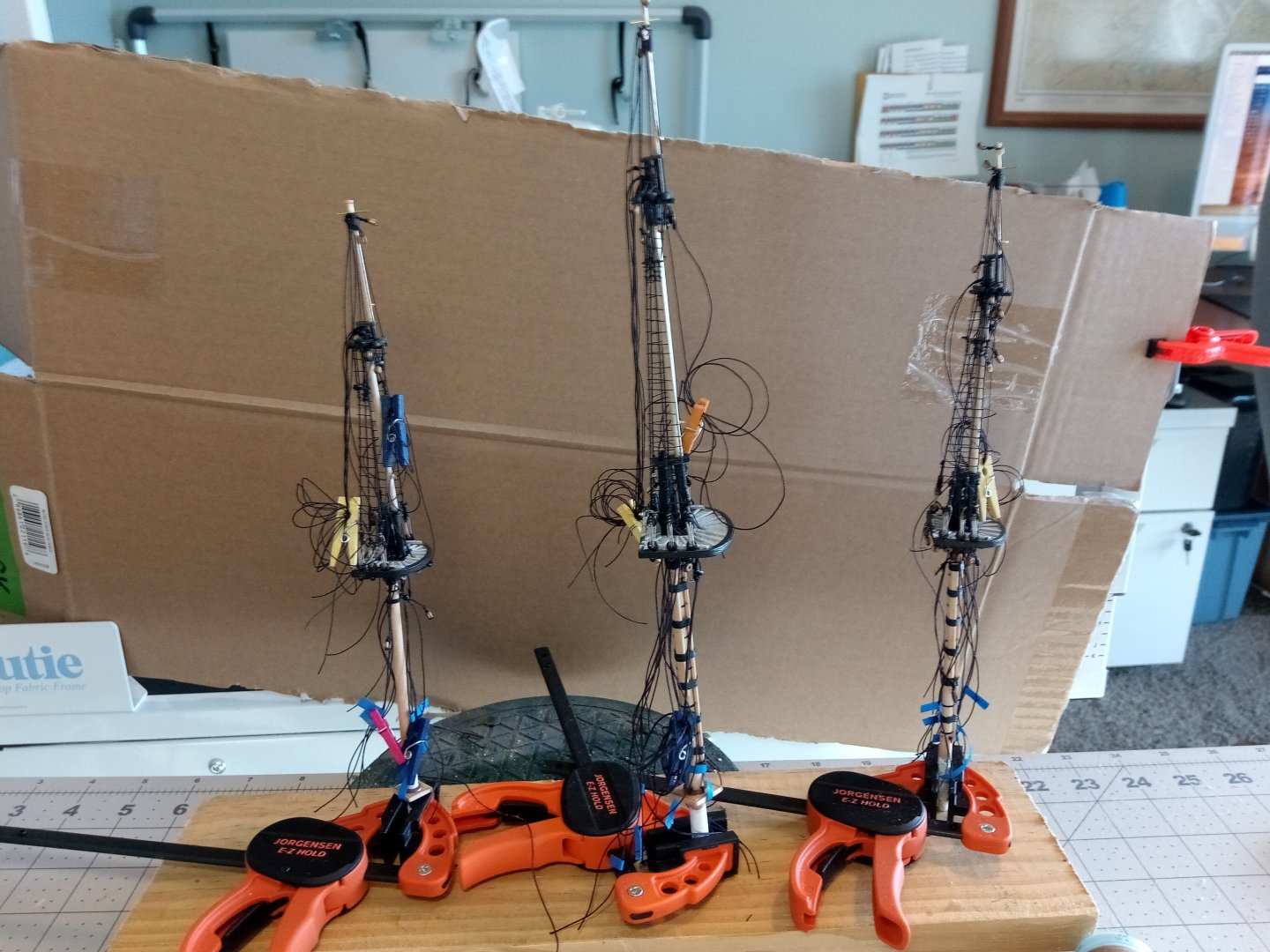
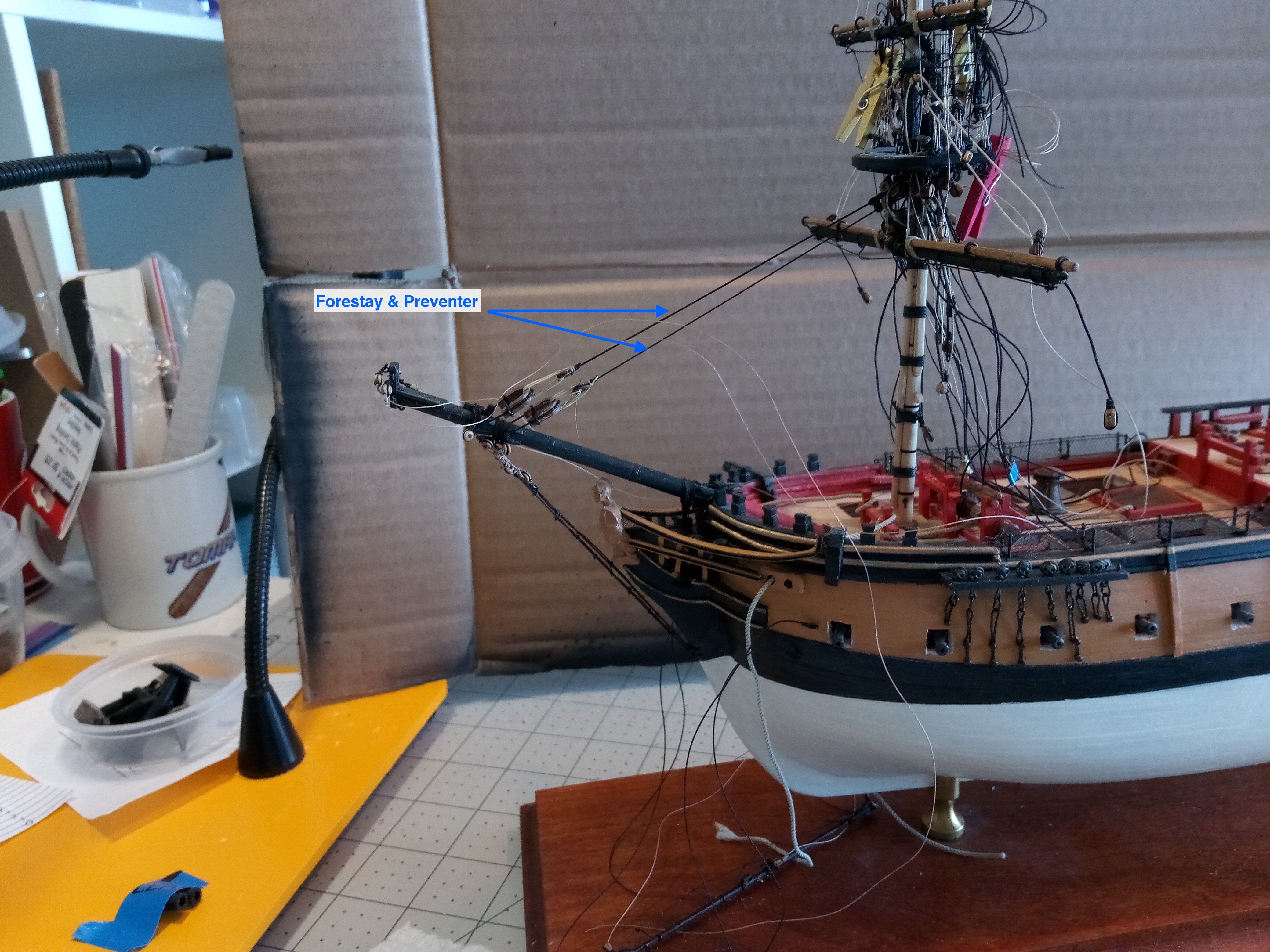
Finishing up the pre-rigging
I’ve finally reached the point where all of the rigging that I feel I can attach to the masts is in place:
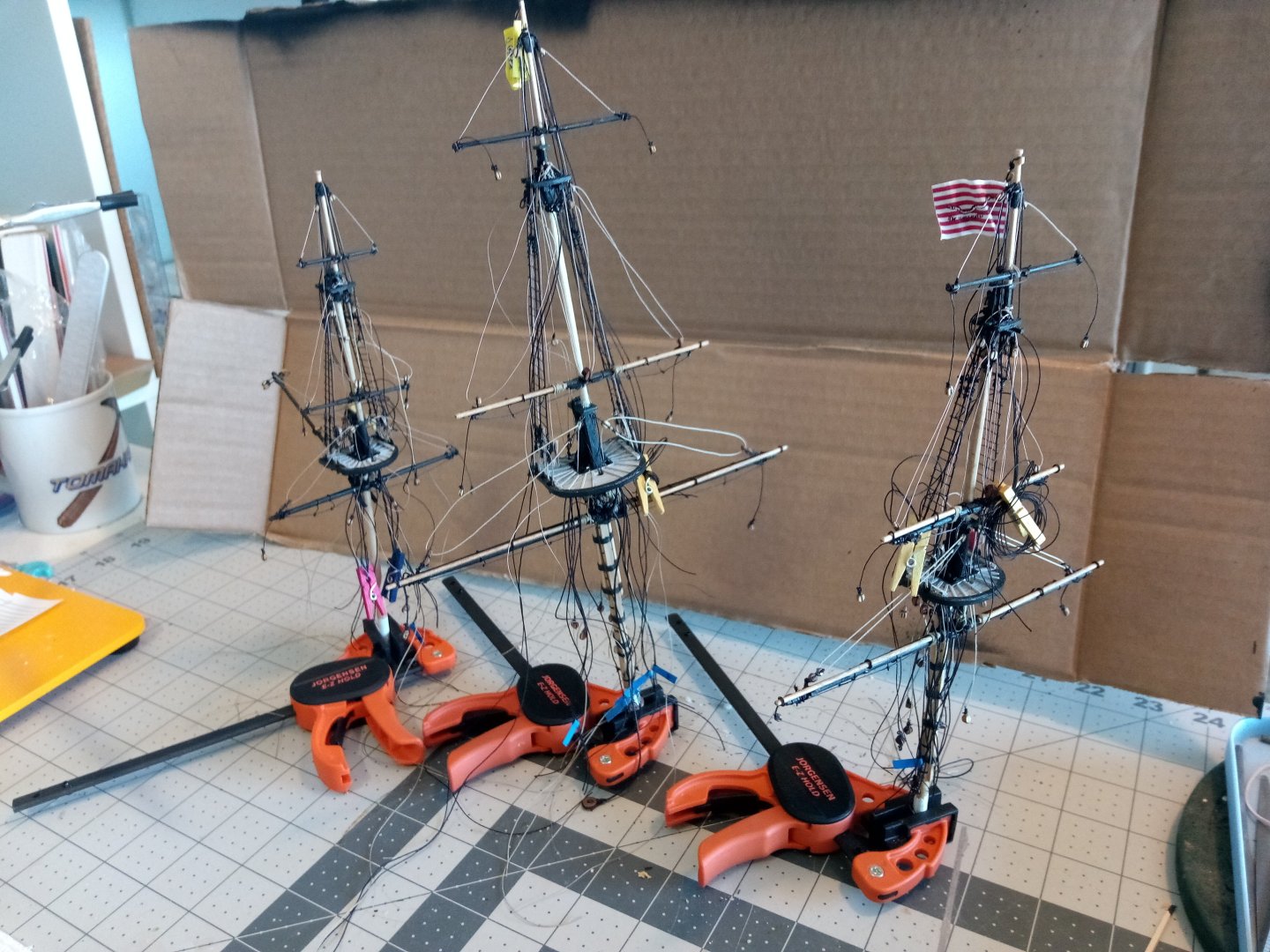
The foremast is the first one that I’ve stepped.
The general sequence that I hope to follow is to attach the fore stays, then most of the rigging around the bowsprit and jib boom and then to belay the running rigging that goes around the base of the mast.

Hopefully I remember what all those lines are for.
- David Lester, ccoyle, KurtH and 1 other
-
4
-
Typically wonderful build! Congratulations.
-
Great choice! Seeing her brings back some great memories - I lived just outside (saltwater side) the locks and saw her often and, like you, served as an oiler on her for a couple of years in the early 70's (when she was only half a century old).
Good luck!
- yvesvidal, Ryland Craze, mtaylor and 1 other
-
4
-
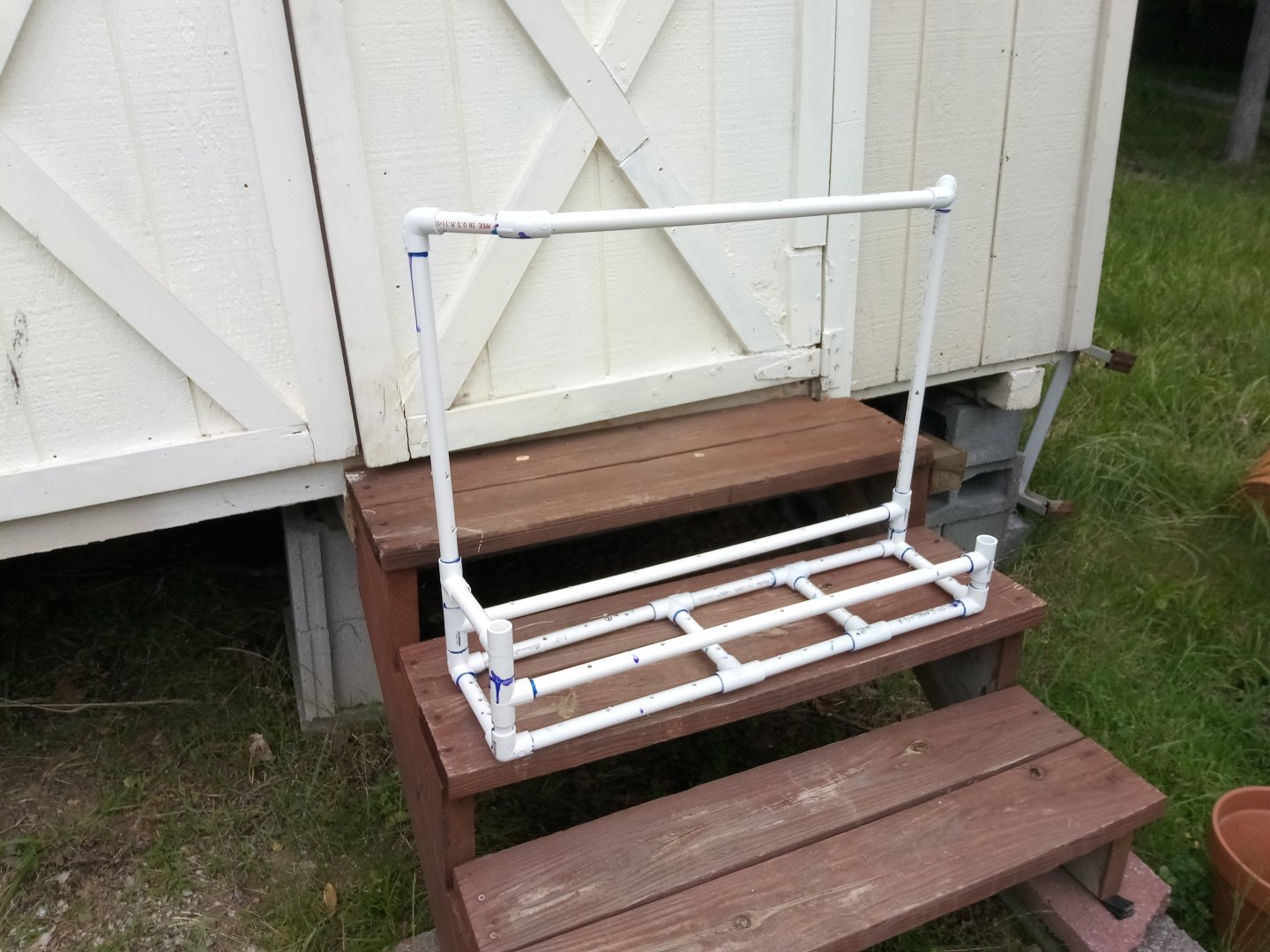
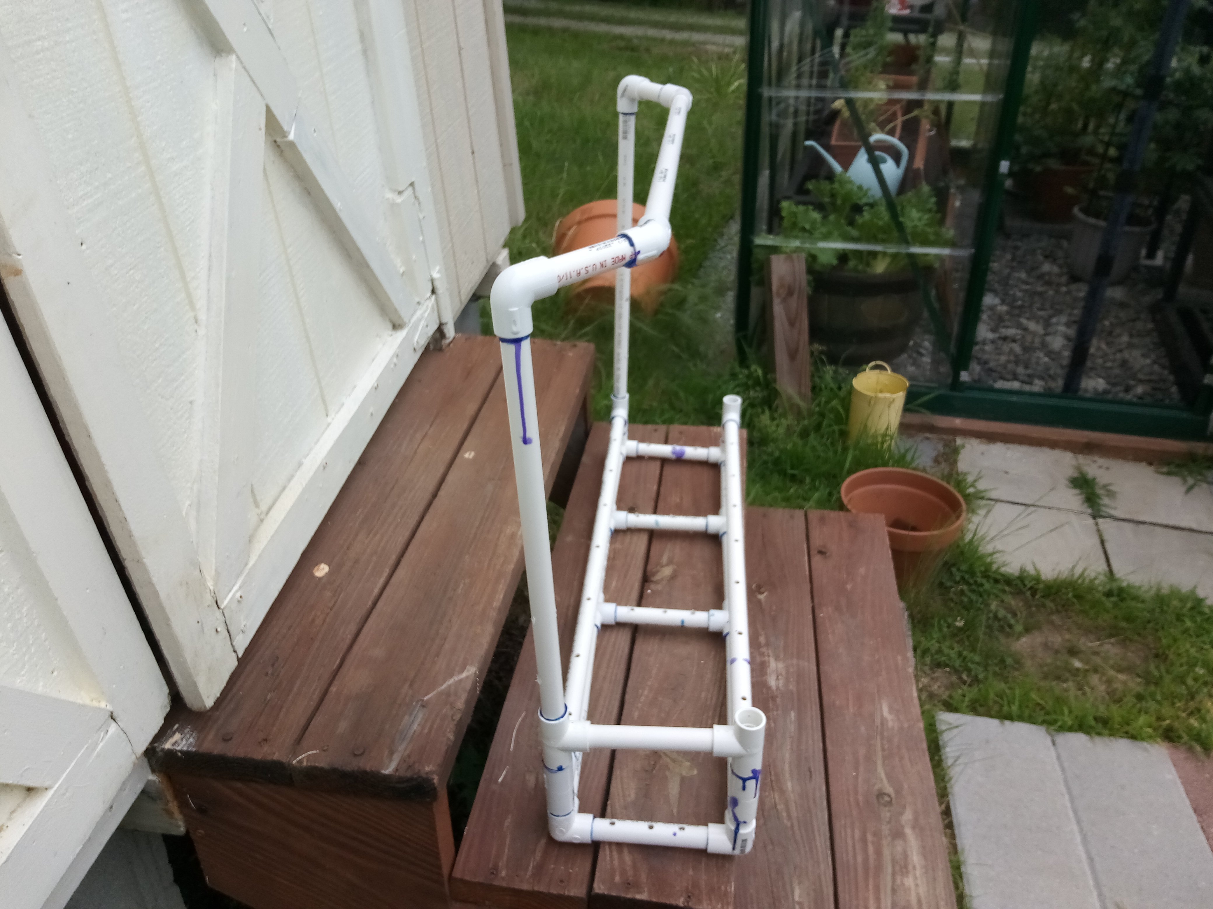
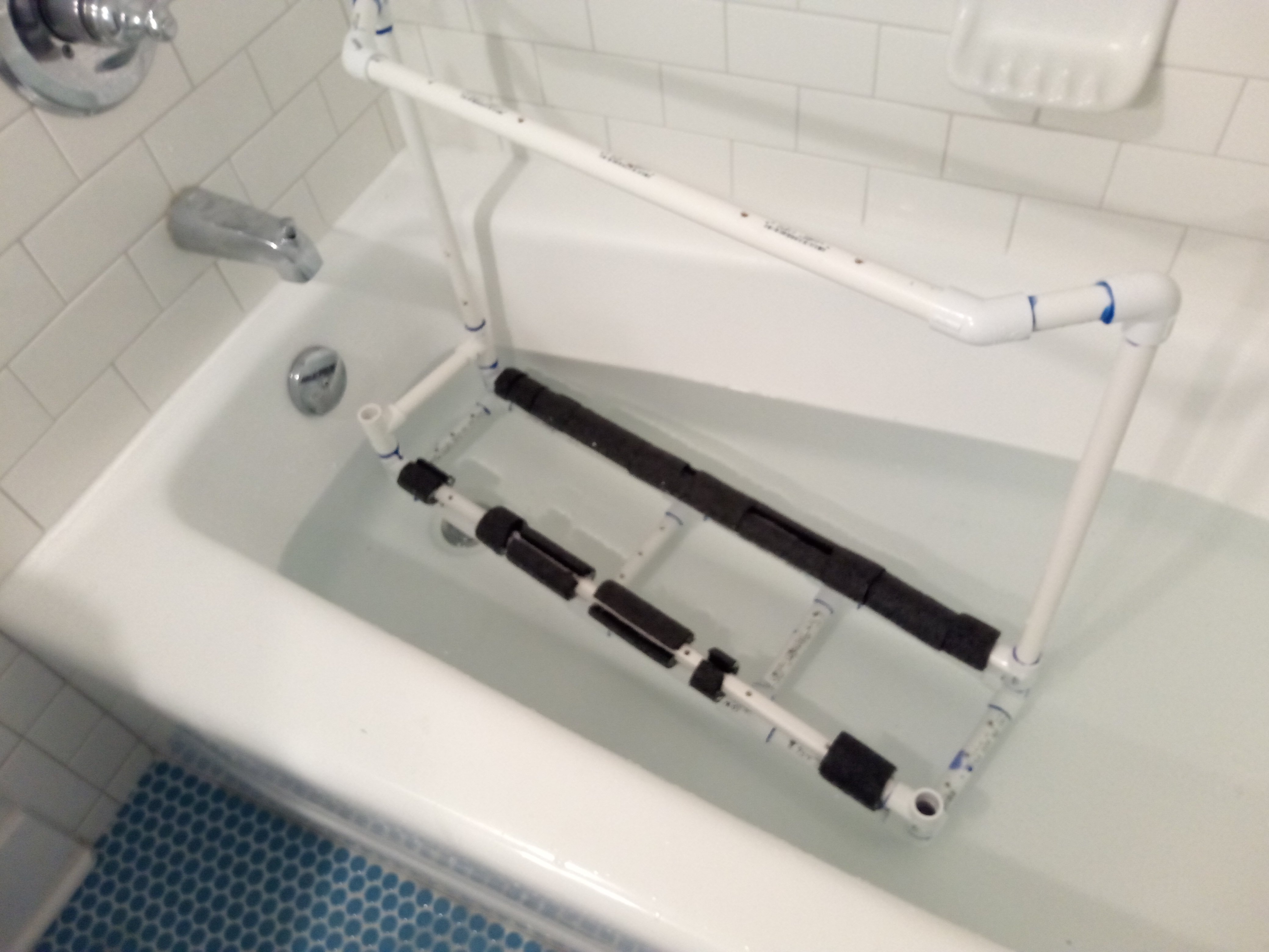
Launch and Recovery Cradle
I would like to launch and recover the model off my dock which sits about 3 ft above the lake, I also needed something to safely “grab” the model if I had to take a boat out to recover it.
I saw a cradle on the build log for a RC Liberty Ship over on the scratch build part of the site. Although that cradle was made of copper pipe for a much heavier model I thought I could get away with lighter, and easier to work with 1/2 inch PVC piping and fittings.
Although it took a few trips to the hardware store to finally get everything I needed it was pretty easy to put together. The bottom is flat but someone with more PVC and design skill than I have could use 45-degree connectors to fashion a “V” bottom which would be best.
I originally intended for the high “handle” section to just be straight up from one side but when I tried lifting it before glueing everything together I found that there was no way that would work, even without the weight of the model on it. I was able to use a couple of 45 degree connectors to move the handle over the centerline of the cradle so it lifts level without tilting.

A couple of tips for anyone thinking about using PVC for a cradle:
- PVC is not buoyant, which is good because it’s easier to add flotation than weight.
- The primer and glue used to bond the PVC pieces sets up VERY quickly (less than 5 seconds) and very strong so you don’t get any do-overs if you don’t get the pieces aligned quickly
- Hardware stores carry 1/2 inch foam pipe insulation that fits perfectly around the PVC without need of glueing or taping unless you put it on a vertical section
- A PVC cutter works great but a saw will also work
- Don't forget to drill plenty of fill and drain holes - even the upper portions that never get wet, you don't want trapped air to mess up your desired floating depth
The bathtub test took awhile. After adding enough flotation to get the thing to float it was VERY unstable - wanting to tip over in both directions. Adding, subtracting and shifting the foam flotation around didn’t make much difference. I finally figured out that the problem was that the high handle section raised the center of gravity above the center of buoyancy - something you don’t want for any floating object. I found that if I shifted all the foam pieces from the bottom horizontals the the upper ones, which are only about 3” higher, the problem was solved. I guess it really is better to be lucky than good.

The cradle floats low enough in the water that the model can float free of it for launching and it can be driven back into it for recovery (the cross piece keeps it from driving thru it).
The next step will be to try it on the lake, hopefully this week.
-
Agree with the hobby shop recommendation.
You might be having the same problem I had - everything worked great until I put the deck on and then things went bad. The problem was that the deck pushed on several wires causing them to move slightly - enough so that the weak solder connections would cut out. Not being a good solder guy I just removed them and twisted the wires together.
Good luck - you are really close now.
- thibaultron and bcochran
-
2
-
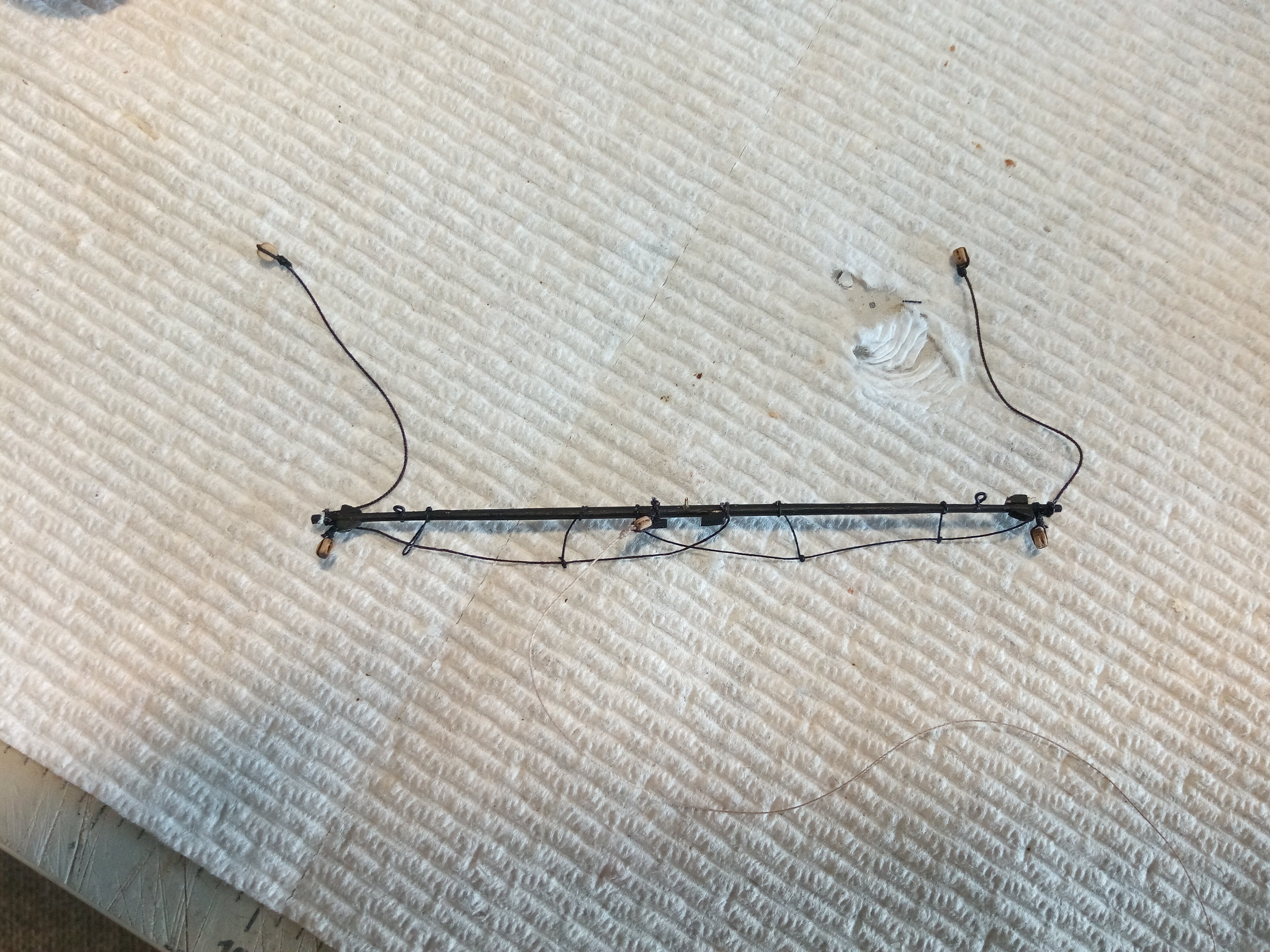
Fore Yard
There is a lot of rigging to do in a small space in order to attach the fore yard (and the lower yards on all the masts).
There are 4 sets of rigging that do different things:
JEERS - 2 pairs of 3&4 sheeve blocks used to hoist the yard into position
SLING - 2 bulls eyes lashed together to support the weight of the yard when it is in position
TRUSSES - 2 heavy lines that loop around the yard and that are then passed thru thimbles (on their partner) behind the mast. They hold the yard to the mast and prevent it from pulling away under pressure of the fore sail
NAVE LINE - I don’t understand how this one works - it is a small line that has 2 thimbles that go around the truss lines and it seems to be a way to either tension the trusses or to counter act the downward pull of the tackles that tighten the trusses
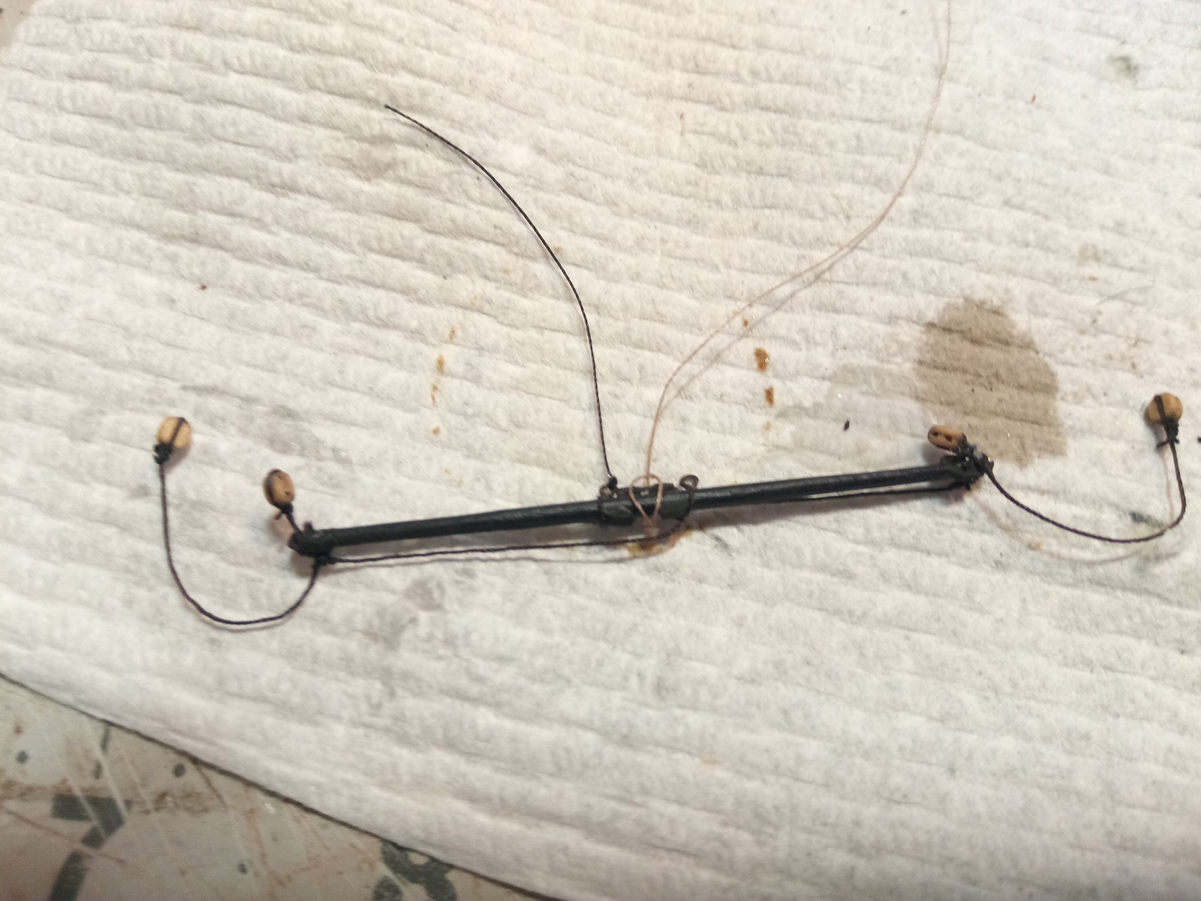
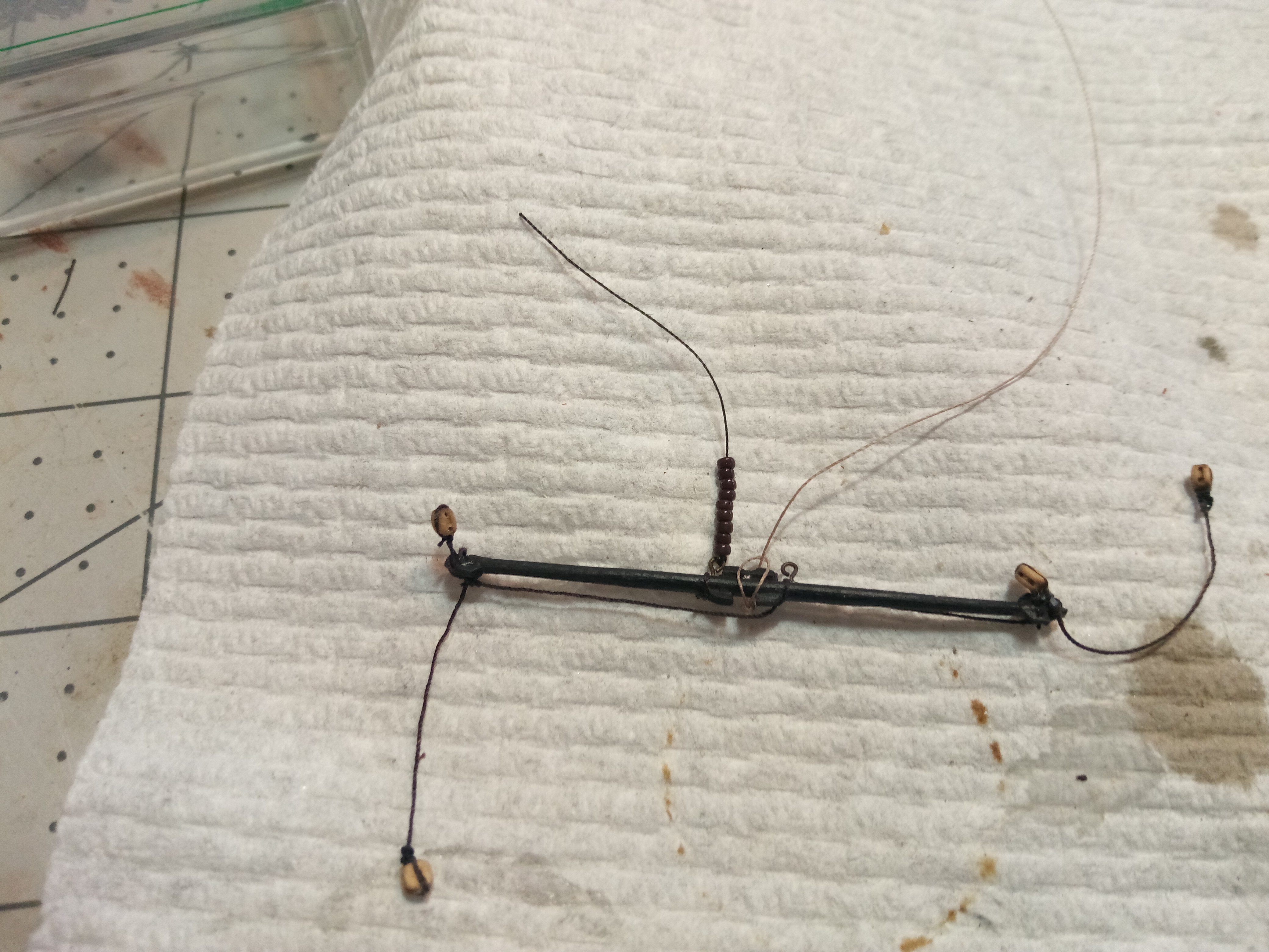
Here is the yard with the sling, jeers, and truss lines pre-rigged on it:
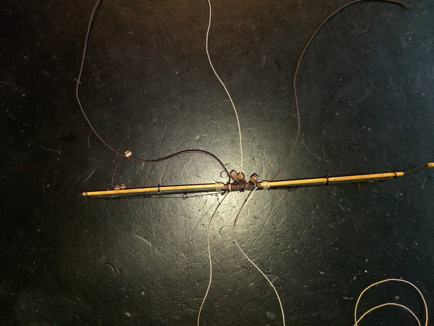
Here is the Nave line that sits behind the mast, just under the to:
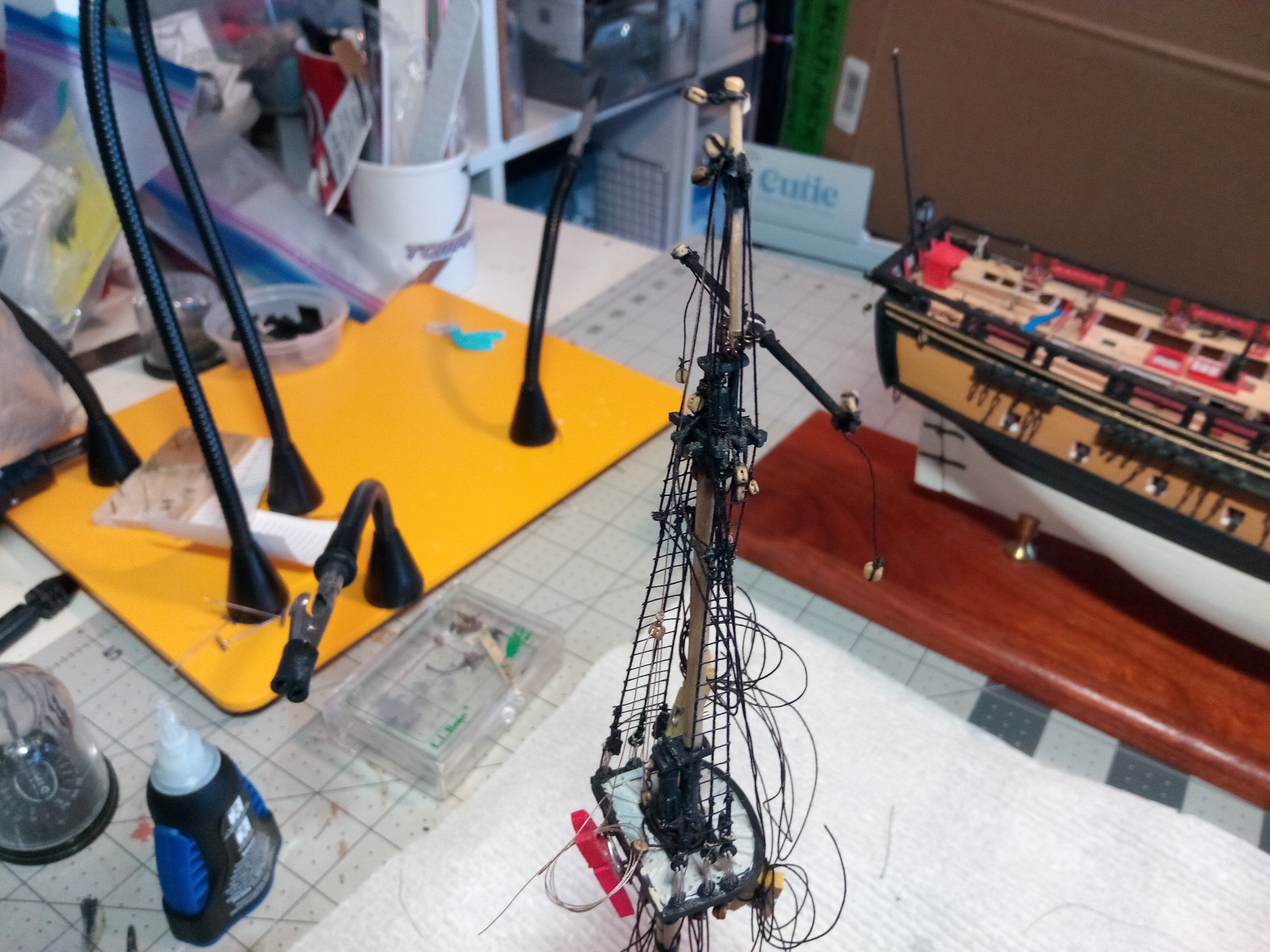
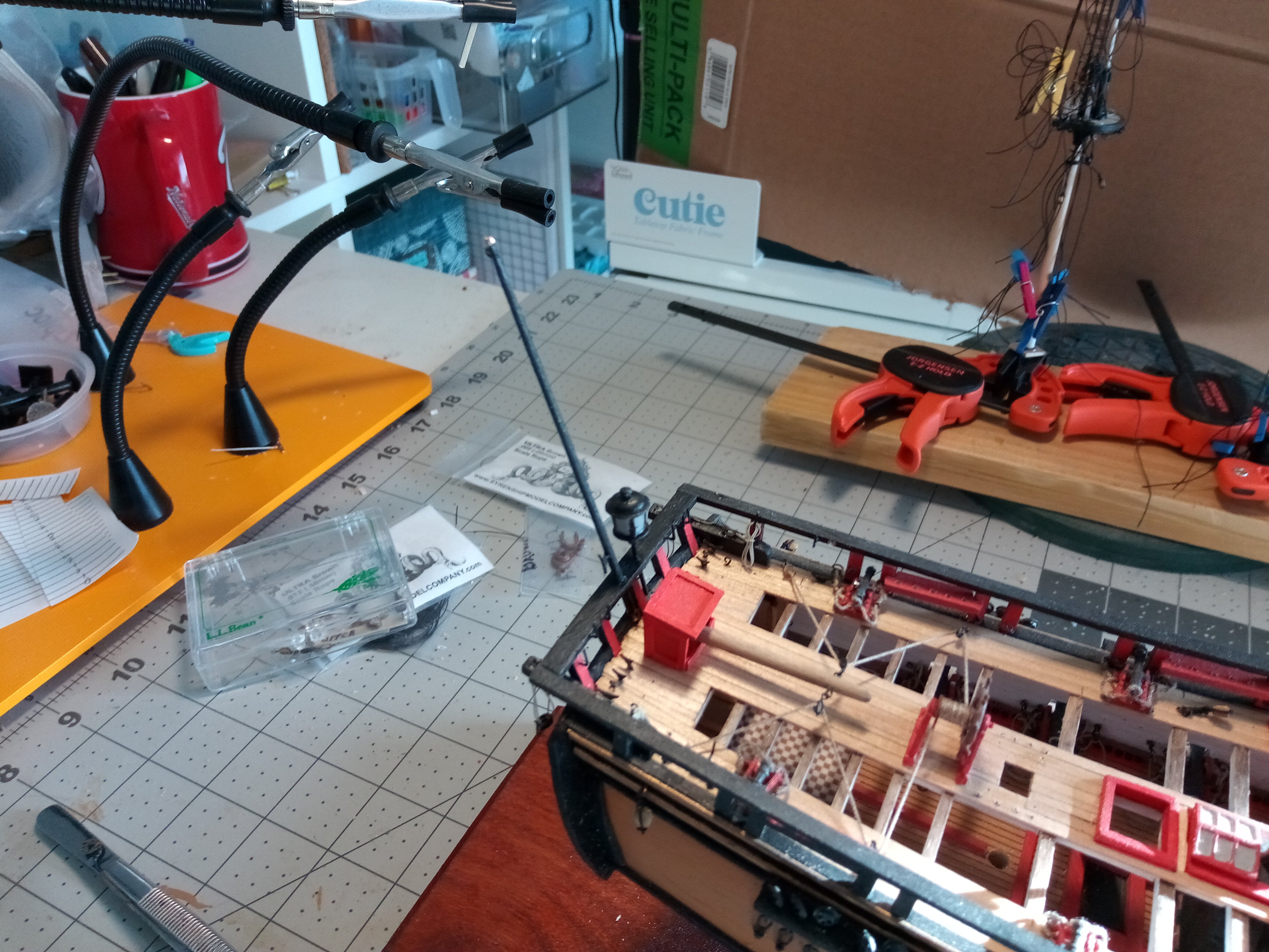
With the Fore Yard in place I’ve reached the limit of what I can reasonably rig to the mast prior to stepping it.

There are about 40 shrouds, stays and running rigging lines that will have to be secured to belaying pins, tackles and deadeyes once the mast is mounted.
I’ll be repeating all this for the other 2 masts and will post again when they are done.
- catopower, mort stoll, whitejamest and 1 other
-
4
-
-
Just so you know - those are High Frequency(HF) fan antennas, 3 thin wires coming down to a common securing point with an insulator. Since the base is not painted with red as a warning for HF burn hazards they are likely receive antennas vice transmit. Either black thread or silver wire can be used to simulate them.
-
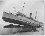
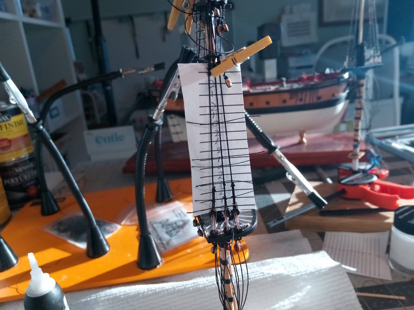
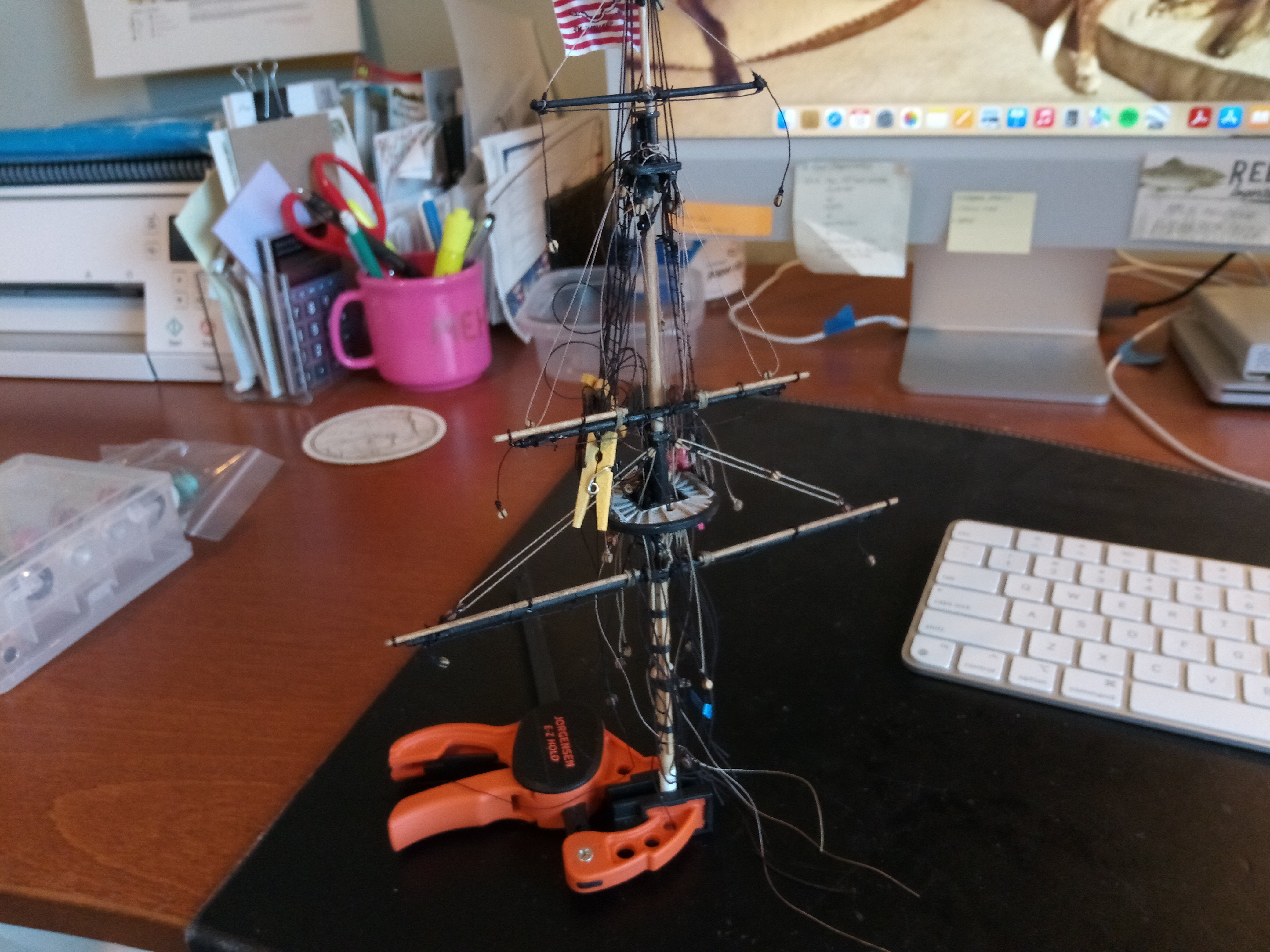
Fore Topsail Yard
The yard was pinned to the mast and the parrel beads added just like the topgallant yard.
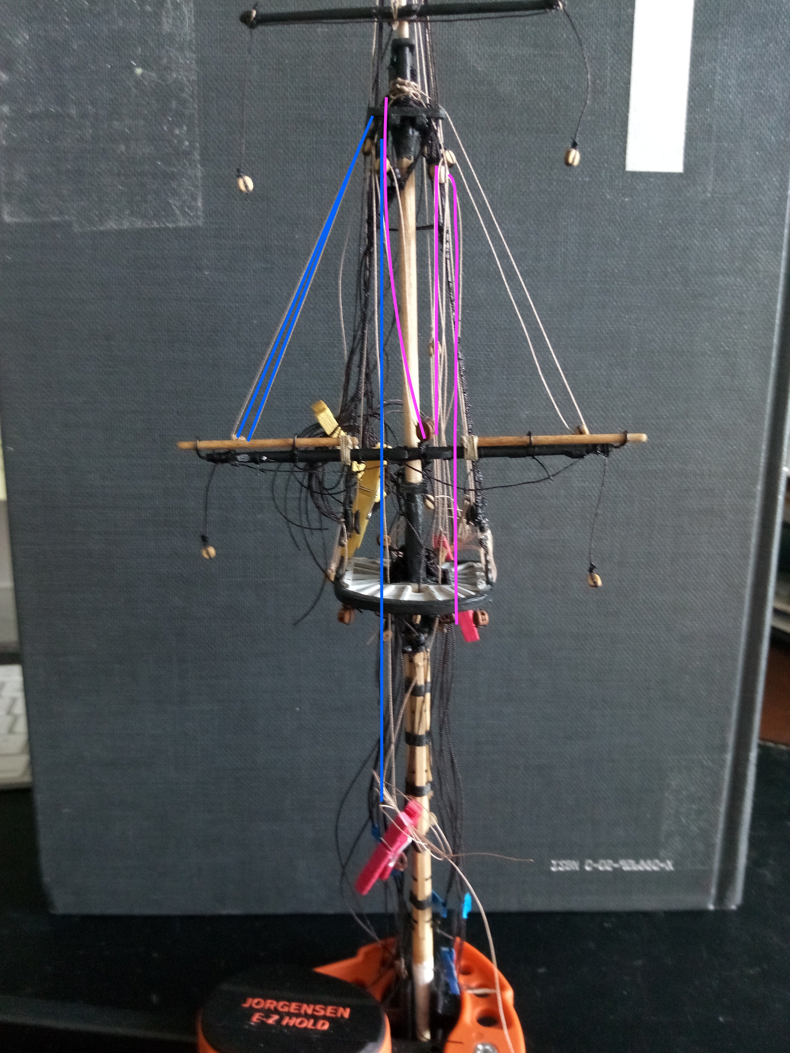
Instead of a simple halyard, as on the topgallant, there are two lines - the Halyard and the Tye, the are identical, just mirror images of each other on opposite sides of the mast. One of them is shown in the photo by the pink lines as it comes down from the crosstrees, passes thru a double block, back up thru a single block hanging from the cross trees and then down to just below and aft of the top where it terminates in a double block that will form the upper part of a tackle that will go on down to the outer edge of the main deck.
The other item are the lifts, one per side, one of them is shown by the blue lines on the photo. They come down from the crosstrees, thru a single block at the yard end, up thru a single block near the cross trees, down thru the lubber hole and down to a pinrail on the deck.
These lines look pretty sloppy because they are slack, they will look better when put under tension.

- mort stoll, ccoyle, KurtH and 3 others
-
6
-
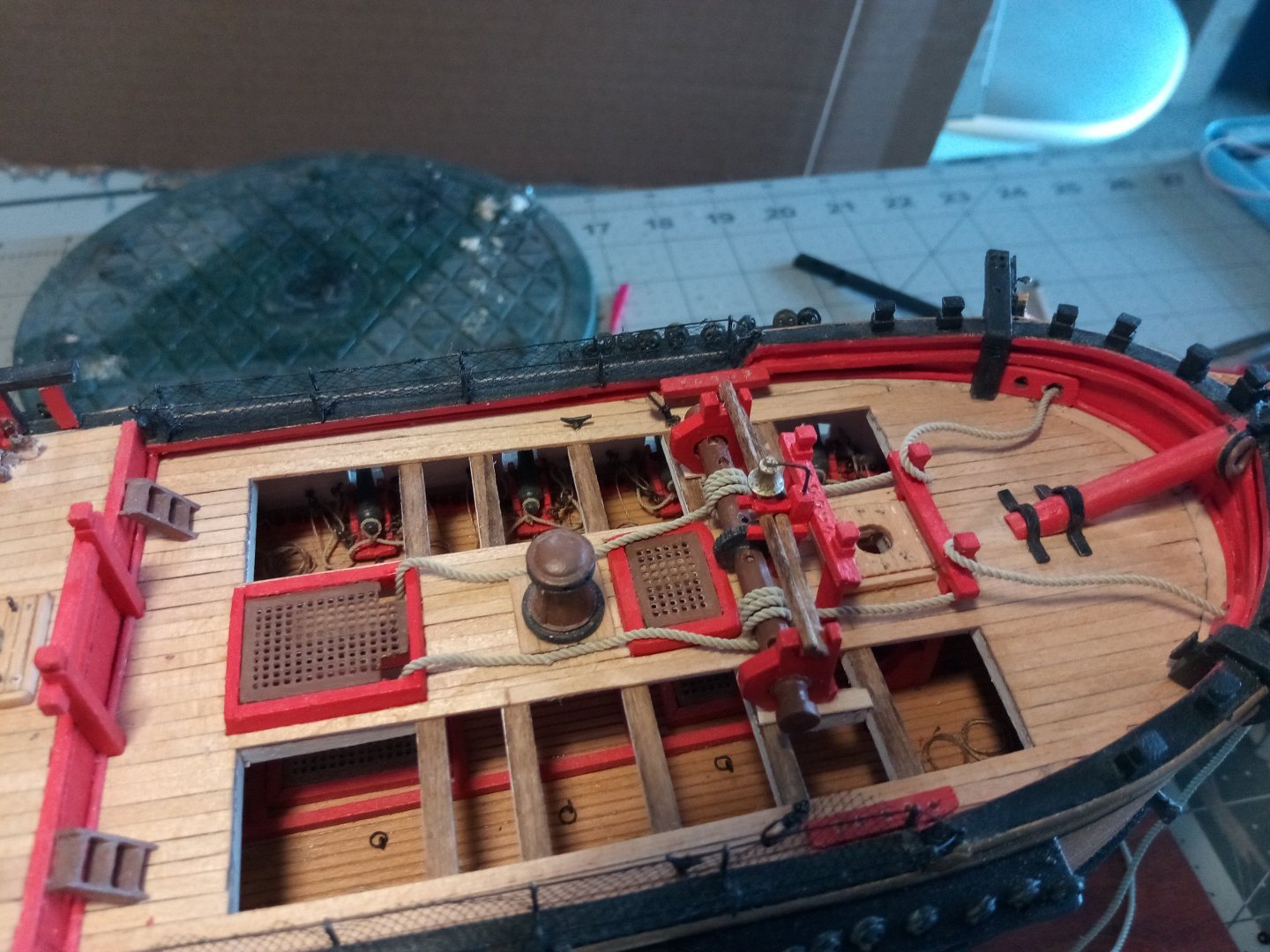
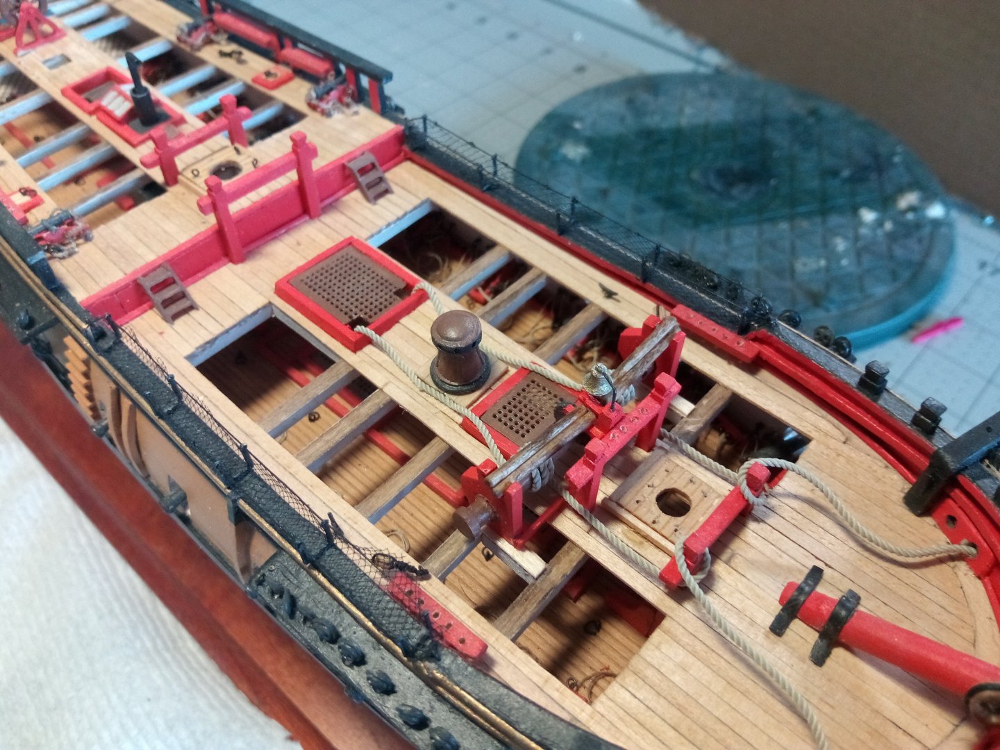
Anchor Windlass
The instructions recommend leaving the anchor windless off until the rigging is completed but I thought that might be tough to do with having to wrap the anchor cables around it so I checked the belaying points for all the belaying pins and tackles in that area and decided it would be best to do it now.
I fabricated a few windless bars for the storage racks and then put the windlass and cables in place:
Fore top gallant yard
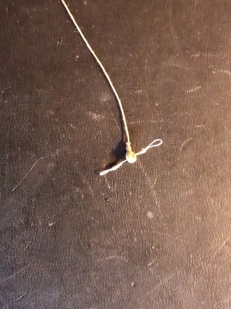
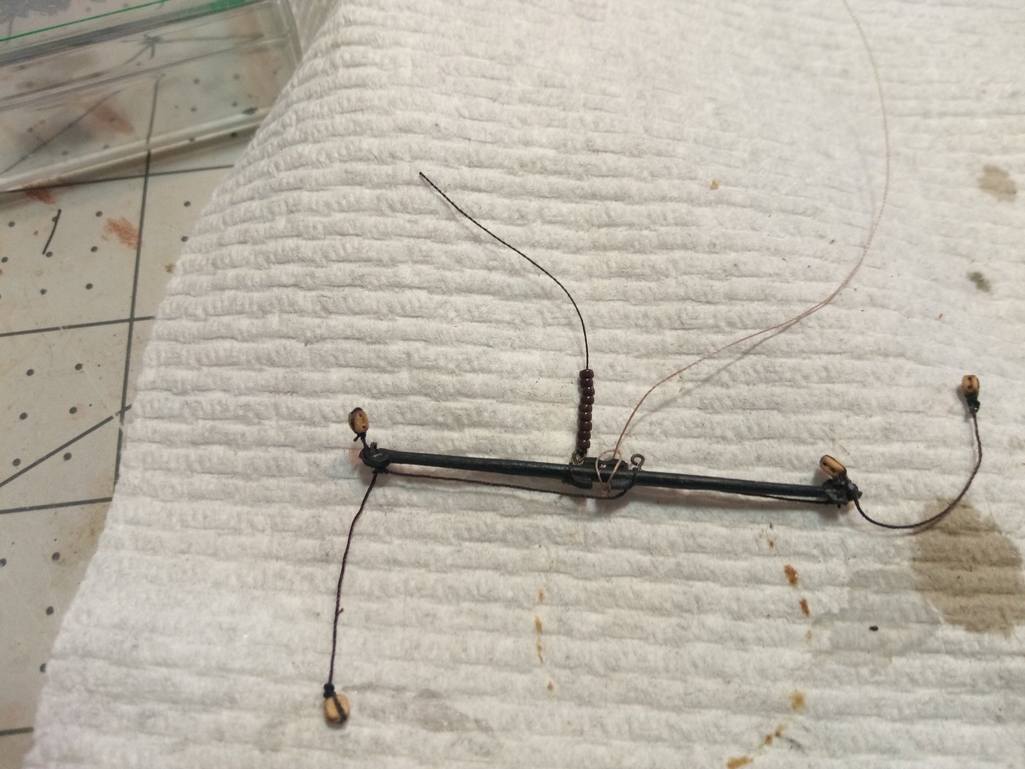
The halyard for the yard is just a line with an eye that turns it into a barrel hitch:
Here the halyard is in place and the parallel beads are strung:

The yard has been pinned to the mast, the parallels secured and the halyard has been run thru a “sheave” hole near the top of the mast and seized to a double block above a single block previously placed on the fighting top. The two blocks are reaved into a tackle, the bitter end will be belayed to one of the pintails on the main deck:

The last things to add are the yard lifts and a flag:
- catopower, whitejamest, KurtH and 1 other
-
4
-
-
-
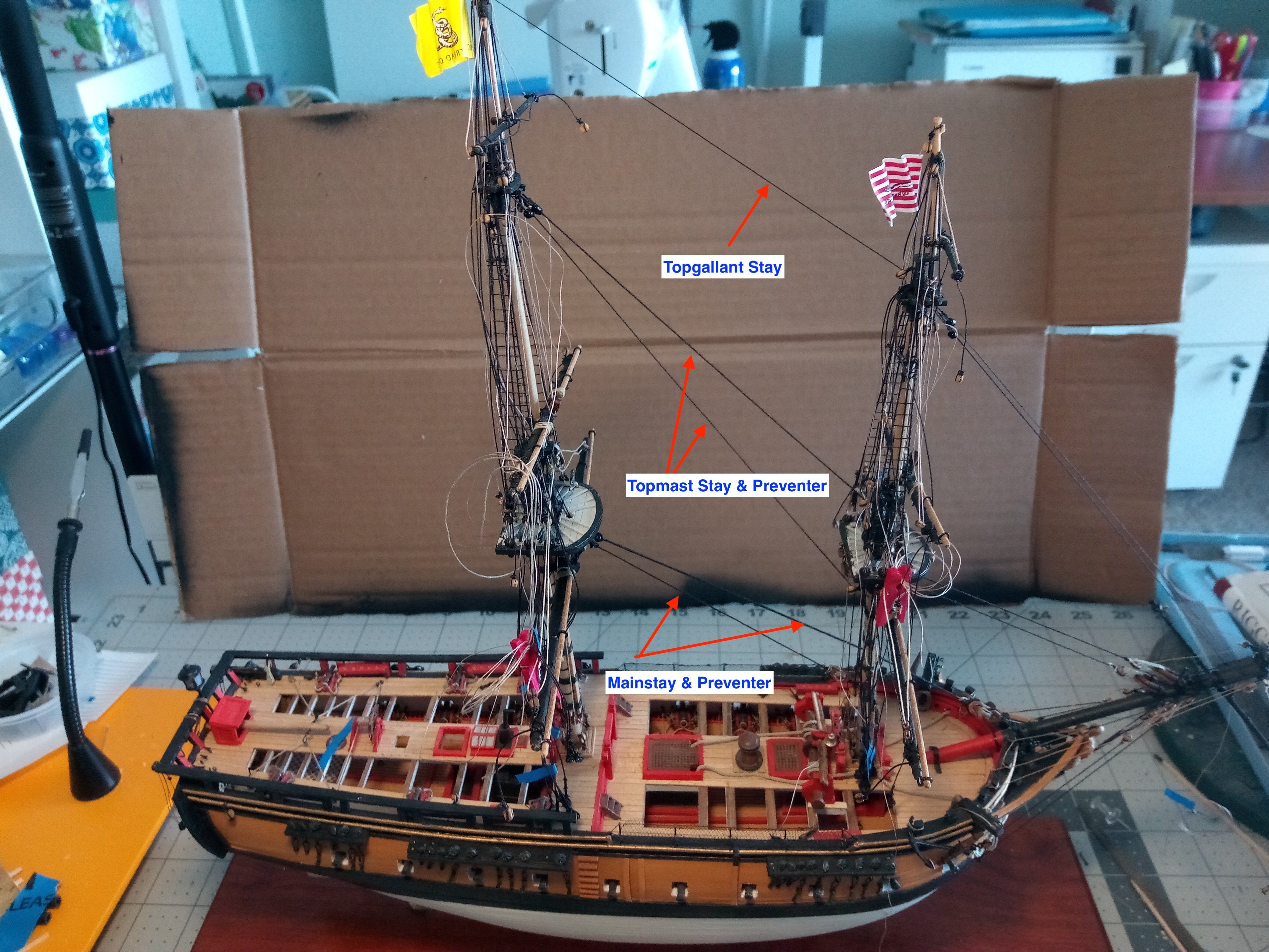
Almost all of the standing rigging has been added to the masts to include:
- upper shrouds & ratlines
- lower shrouds
- backstays
- forestays and their mouses (mice?)
I’ll hold off adding the topgallant stays until later in the build because it would be very easy to snag one an break off a delicate topgallant mast
The brass rods that are sitting near the top of the topgallant mast are just placeholders - they keep me from accidentally covering up the topgallant yard sheaves.
Needing to take break from all the thread and tweezers I worked on a few minor items such as adding the stern lantern and ensign staff

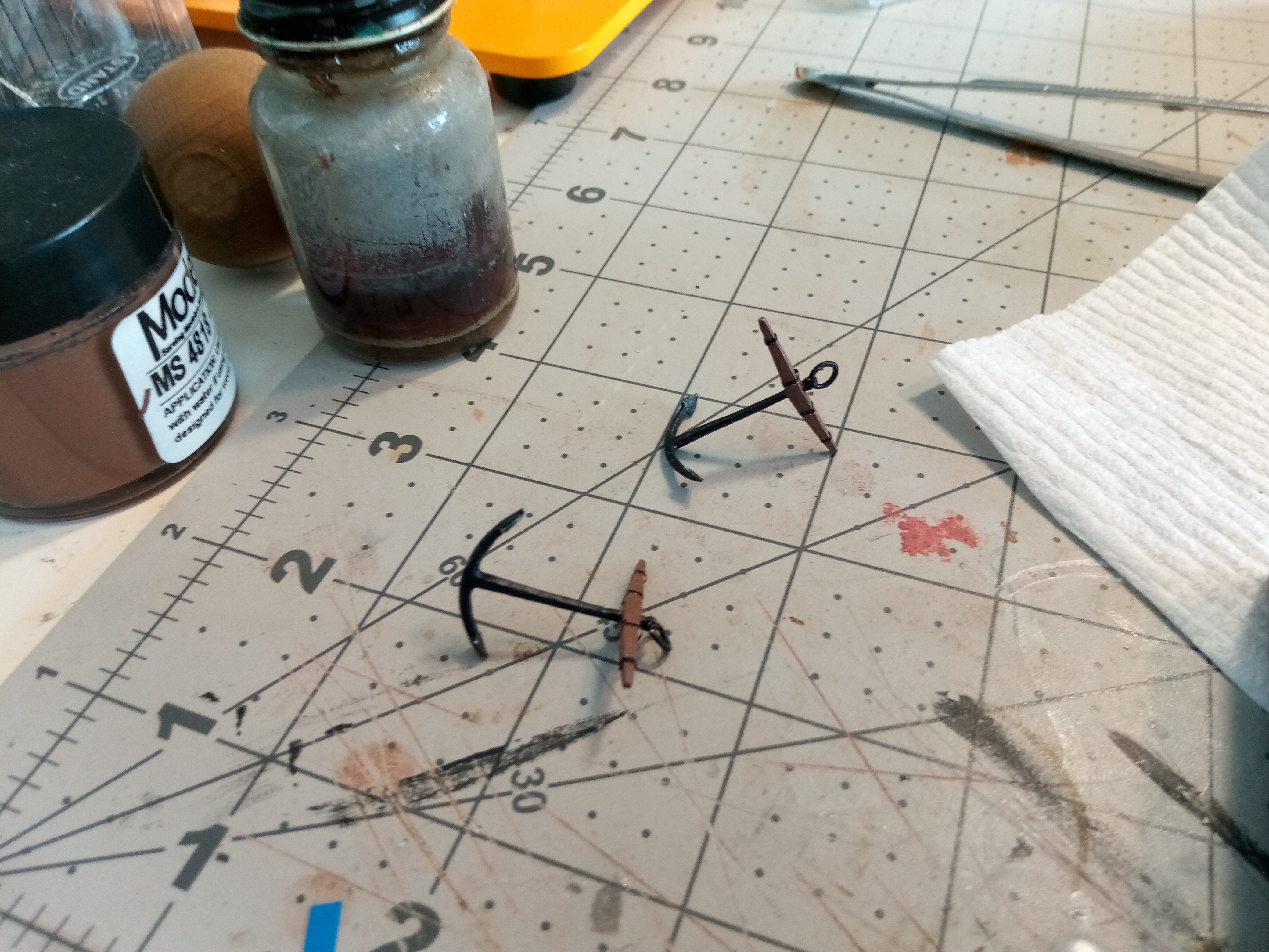
Fabricating the anchors

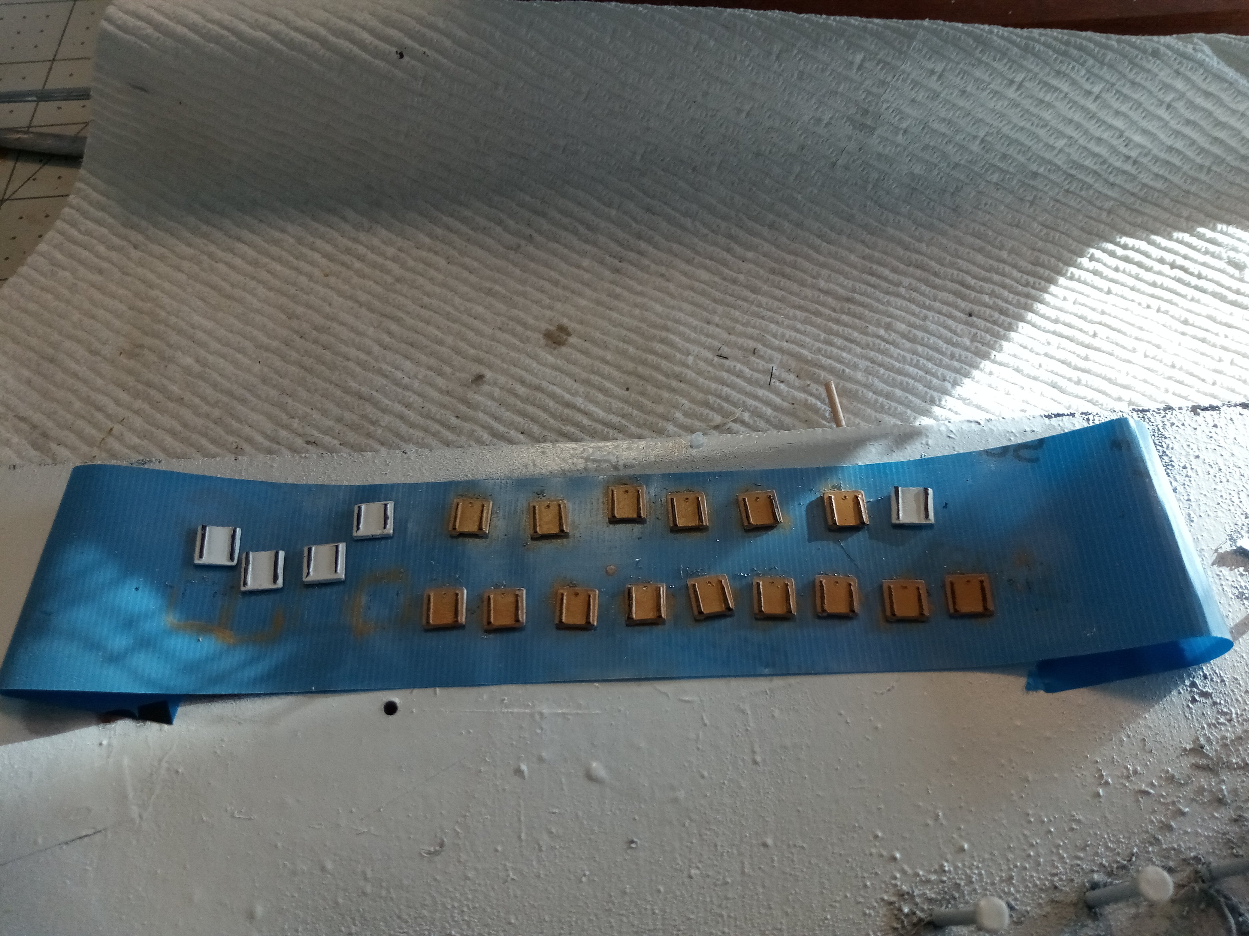
Painting the gunport lids

Next up will adding the yards to the foremast
- David Lester, KurtH, mort stoll and 1 other
-
4
-
Great job!!!
The hull lettering looks very nice, are they decals? stick on letters? painting stencils or something else?
- Jeff preisler, Canute and Mirabell61
-
2
-
 1
1
-
Upper Ratlines
I prepared for adding the upper ratlines by adding the Futtock Staves below the crosstrees and then the carpathans:
The process of adding the ratlines was slow, mainly due to a case of “two steps forward, one step back” as I figured out how to tie them and then had to remove them to try something else.
Although I use clove hitches on my “real” boat all the time they are made using rope (obviously) and usually tied around a horizontal bar. Trying to tie them with thread around another vertical thread kept confusing me. I finally found a great little video on Bruma’s build of the Revell plastic kit of the CUTTY SARK. His video is helpful because the thread is large, he works slowly and best of all, he uses tweezers for everything so his fingers are not blocking the view. It is on post # 366 of the attached:
After watching it several times I finally got it in my head how to do it.
My first attempt at tying clove hitches did not go well - I managed to get them crooked and many of the knots loosened up to the point that loops were clearly visible. Fortunately I had secured them with diluted white glue so they were easy to remove after brushing the knots with water.
My second attempt went much better after I figured out how to cinch them tightly. Then the problem was that the knots were simply oversize at this scale. I tried some super fine thread I have but it was to too hard to see it and to manipulate it with tweezers so I decided to remove all the ratlines I had added to that point and to try gluing them to the shrouds.
I’m satisfied with this result:
Next up will be adding the backstays and the fore stays to the masts.
- mort stoll and KurtH
-
2
-
Very nice job with your detail painting! Few paint jobs can hold up to the photo magnification here on MSW but your's looks good no matter how close you look. Cannons look great too.
-
Thanks Keith,
Actually I did try that based on what I saw on your log. The threads I have to use for the upper shrouds at 1:96 are just too narrow (thin) to swing it, even with my wife's thinnest needle. I will try it again when I get to the lower (& thicker) shrouds.
Keep up the great work on the Tennessee, she's a beauty.
- Scottish Guy and Keith Black
-
1
-
1
-
Great build and build log, nice clear photos!
I really appreciate your posting of the video of how to do ratlines back in September. Although I use clove hitches all the time on my real boat somehow when using thread around another vertical thread I keep screwing it up. Your video is great because you tie the knots slowly and your use of tweezers keeps your fingers from blocking the view of what you are doing. I'm no in the process of tying stress-free clove hitches!
- Scottish Guy, Bruma and Keith Black
-
2
-
1


Atlantic by kmurph - BlueJacket Shipcrafters - 1:96 Scale
in - Kit build logs for subjects built from 1901 - Present Day
Posted
Looks like you are off to a very good start! That is a gorgeous kit that really depends on a good paint job to "be all it can be" and it seems like you nailed it.
Keep up the good work.