HOLIDAY DONATION DRIVE - SUPPORT MSW - DO YOUR PART TO KEEP THIS GREAT FORUM GOING! (Only 20 donations so far - C'mon guys!)
×


dvm27
-
Posts
2,457 -
Joined
-
Last visited
Content Type
Profiles
Forums
Gallery
Events
Everything posted by dvm27
-
 Innovative tool Kevin! For planking I would use tapered offcuts as wedges slipped between the ledge of the margin plank and the deck plank being glued. You can generate a surprising amount of pressure with tapered wedges. It's also efficient as you can just narrow them for the next run of planking.
 -
The use of the thin tape to make the reinforcing rings is very clever and looks very convincing Toni!
-
Chuck makes a good point Siggi. Adding that fine molded detail is difficult, especially around curved surfaces. I assume you are using a scraper.
-
Not sure your scraper will work with the rising wood attached but it would be a simple thing to knock off the lower edge of the rising wood with a v gouge if you add the rising wood after gouging the keel rabbet. There are many micro chisels with V-gouges available. for example: https://www.etsy.com/listing/829851705/6pc-ramelson-sub-mini-wood-carving?gpla=1&gao=1&&utm_source=google&utm_medium=cpc&utm_campaign=shopping_us_a-craft_supplies_and_tools-tools_and_equipment-tools-other&utm_custom1=_k_Cj0KCQjwrJOMBhCZARIsAGEd4VFVN-rbOsnoV5afiynLCTWedCa7SWmgSkYYybXi-DfKyItXOfDjyaEaArPBEALw_wcB_k_&utm_content=go_12569400892_126353655504_507394790794_aud-459688892115:pla-295604191622_c__829851705_443242358&utm_custom2=12569400892&gclid=Cj0KCQjwrJOMBhCZARIsAGEd4VFVN-rbOsnoV5afiynLCTWedCa7SWmgSkYYybXi-DfKyItXOfDjyaEaArPBEALw_wcB
-
It is easier to add the false keel sections together directly onto the keel as it is difficult to achieve a good bond over the angled tarred joint. I first glue a strip of black archival tissue paper over one surface, trim it when dry then perforate with pinholes. I seem to get a better bond this way. Additionally I would add the rising wood before cutting the rabbet as the bottom edge of the rising wood is incorporated into the rabbet.
-
They are laser cut in one layer and all the planking is laser inscribed. I had built them originally of three ply layers but always had warping. After a year or so Chucks are still perfectly flat. I have also noted many Navy Board models where the tops have significant warpage. David's amazing carvings are all secured in place (see prior page).
-
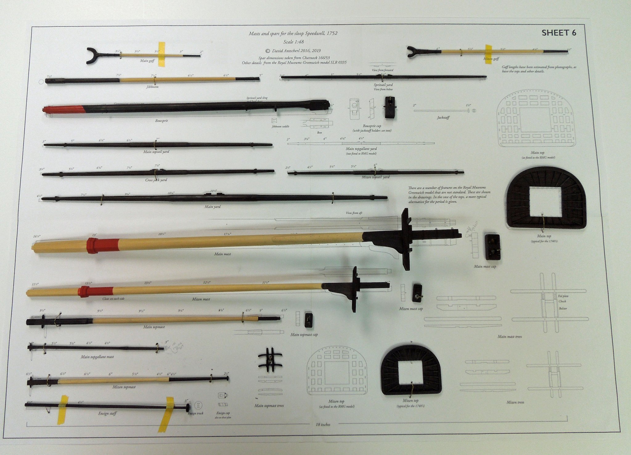
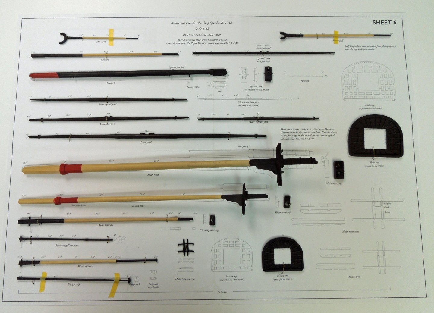
With Speedwell back in her home port I can commence the rigging. I have not sat idly by during her absence though and have fully prepared her masts and spars to expedite rigging upon her return. I will be using ropes and tackle made by Chuck as they are the finest commercially available in my opinion. As well I will be using Johann's excellent Creole log for inspiration. All the masting, sparring and rigging is fully described in volume two of the Speedwell series so I won't be going into quite as much detail as previously. As my last rigged model was constructed over twenty years ago I expect to proceed at a glacial pace. For me the process is more enjoyable than looking at the finished product. In the photo below one can see the unusual tops which are present on the contemporary model. I found them aesthetically unpleasing and have constructed the more traditional top I am used to seeing. If anyone can cite a contemporary model with the original tops constructed as per Speedwells I would appreciate a photo.
- 345 replies
-
- 43
-

-

-
Best of luck on your build. As David suggested, at a minimum you'll need to become proficient with a jewelers saw as there are many complex futtocks in the model. Taking your time and learning how to use files properly can result in an excellent model (as evidenced by Harold Hahn).
-
Great set of photos Chuck. Did you happen to note that besides the excellent carvings the builder actually carved the volute scrolls of the hance pieces in a delicate floral (?) pattern (1109). I thought it was damaged at first but then noted this feature on all the scrolls. I can see how members of the Admiralty could be influenced at the prospect of receiving one of these models as a gift.
- 1,784 replies
-
- 6
-
-
- winchelsea
- Syren Ship Model Company
- (and 1 more)
-
Harold Hahn method
dvm27 replied to Essayons's topic in Building, Framing, Planking and plating a ships hull and deck
When we contemplated the swan class build I asked designer David Antscherl to loft the jig for the Hahn style method. But even for a sixth rate the jig was very complex for properly lofted frames and I decided to build upright. Having built several Hahn style models I actually found building upright just as easy and more fun (I suppose because it followed actual building practice and you don't have to wait for the jig to be chopped away before you truly appreciate the lines of the model). Another alternative that is popular among French builders is to build upright using a jig below the toptimber line. Not too difficult to make if you have the framing plan. -
I think anyone who has built Winnie to this stage should be more than capable of making an impressive belfry with your kit Chuck. You can only simplify things so much before it affects the quality of the final product. I've built a couple of your mini-kits and achieved great results with patience and a light touch.
- 1,784 replies
-
- 9
-
-
- winchelsea
- Syren Ship Model Company
- (and 1 more)
-
I too shall look for a similar item in the US as I am just starting to rig. Great idea Johann!
-
Having pre-ordered my book months ago I just received notice that is was shipped but with the Brexit problems it will take several months to arrive. Of course I could have had the same book in two days from Amazon if I had waited. As they both come from the exact same publishing house it's stupefying how different the delivery times are. It must be wonderful to be Amazon!
-
I was thinking of showing my Speedwell in progress at the show but I was afraid the temporarily placed carvings might disappear. Guess I was right to be hesitant. RIP little Chucky! I hope a disgruntled client didn’t lift it for voodoo purposes. Any unusual aches and pains lately Chuck?
- 1,784 replies
-
- 7
-
-
- winchelsea
- Syren Ship Model Company
- (and 1 more)
-
Nice job on the waterway Kevin. The purpose of the waterway was to provide a seal between the side and deck planking. Water seepage would lead to beam end and surrounding wood rot. So this timber had to be very robust and secure from moving. Hooked scarph joints are quite strong and would help prevent separation along the waterway. Some authors consider the waterway to be part of the side planking as opposed to deck planking.
-
Wonderful work, doesn't appear to need much fairing at all! I see you decided to do the hawse holes at a later point. After ruining a few hawse pieces I opted to cut them in later as well. I note on my 15 year old Swan class model I've had no gaps appear between the filling pieces between the floors of the frames. Perhaps that's because it's in a case in a temperature controlled environment. I did have gaps appear in my current Speedwell model but I think that's because she's been moved frequently to areas of different temperature and humidity.
-
Congratulations on completing a very difficult section Bruce! Your model is looking very nice. This is my first visit to your log and I note the gratings in the waist are very different than those on the quarterdeck. Would you consider replacing the ones in the waist with Chuck's kit versions as they are not period correct and to me detract a bit from your otherwise excellent work.
-
I knew you could do it Kevin! Few tips regarding your latest video: 1. Deflection is always a problem with small diameter parts. You get much less deflection using wider stock. Just turn the amount you need to the final diameter but leave the tailstock portion wide. 2. Always use a center drill. Sherline makes some very small center drills that are perfect for sheaves (0, 00). 3. While parting small drilled items insert a wire into the end. This way they won't fly off and leave you cursing when you can't find them. 4. There are some very fine Vallrobe Swiss files that taper almost to a point. They are perfect for forming the concave part of the sheave and deadeyes freehand while the lathe is running.
-
I have good success using the widest blade (0.0625") I have for my Byrnes saw. The key is to leave the top overlong so both ends are always parallel and resting on the table surface. Otherwise, as Kurt said, you can introduce wobble. You can create rather long slots by nibbling away at the piece then running it through in one pass lengthwise to unify any missed sections.
-
Even though the gaps would be imperceptible on the finished model you have set an excellent precedent for future work. if you neglect a small detail that's not to your liking now it becomes easier to ignore the next one...and the one after that. I think you'll be very pleased with this model, no matter how long it takes.
-
Depending on the location of the high spot you could spot glue a strip of 120 grit sandpaper to the rising wood and deadwood. Gently rub the underside of the keelson over its position until the gap disappears. Just a few passes, reassess, then a few passes until you creep up on it. This worked well for me. But in all honestly this gap will be invisible in the finished model.
-
I found it convenient to temporarily glue the drum pieces together, turn to the final diameter, unglue them then mill the slots for the capstan bars half way on each piece using the mill rotary table. They were then reglued forming the fully thicknessed capstan bar mortises. I thought this would be easier than drilling evenly spaced holes and turning them into squares. But I'm sure you'll figure create the same effect.
-
HMS EURYALUS by Matiz - FINISHED - scale 1:56
dvm27 replied to matiz's topic in - Build logs for subjects built 1801 - 1850
Cutting those sill mortises perfectly is no easy task Matiz. As usual your work is perfection. I like your little mini-clamp which you are using to prevent the frames from shifting while working on the sill mortises. -
That's the way I do it. I mill off two of the surfaces of the nut to fit into keelson slots to receive them. They are epoxied in place. If you could add an additional bolt fore and aft of the original two that would be sufficient to secure the hull whatever display you choose.
-
Swan-Class Sloop by Stuglo - FINISHED - 1:48
dvm27 replied to stuglo's topic in - Build logs for subjects built 1751 - 1800
Due to illustration reproduction problems we have had over the years I would always go with the stated dimensions.