


Mike Y
-
Posts
1,513 -
Joined
-
Last visited
Content Type
Profiles
Forums
Gallery
Events
Posts posted by Mike Y
-
-
Carl, I fully agree that it is better to oil after the installation, but these pieces are going into the very confined places, reaching them after the installation would be very hard.
Oil sips a bit, roughly 1mm from each side. Scraping and filing easily removes unnecesary oil from the surfaces that would be glued, if the oil was not applied directly to that surface, otherwise it can sip to deep, escpecially cross grain.
-
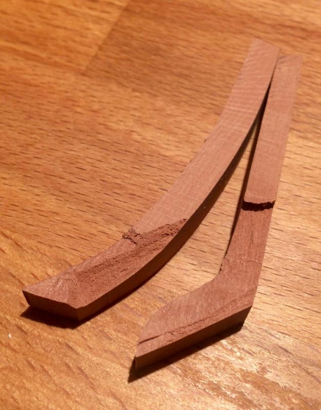
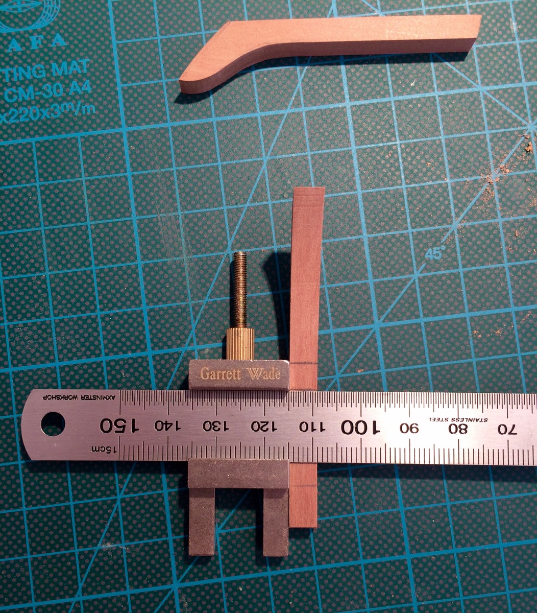
Worked on stemson and sternson today. Hahn plans omit both, so it is another thing that is up to the builder. TFFM depicts stemson in a quite detailed way, and I found sternson in Ed Tosti's Naiad build log:
Nobody knows if Oliver Cromwell had a sternson, but decided to make it anyway to cover mistakes done in the center of transom wings.
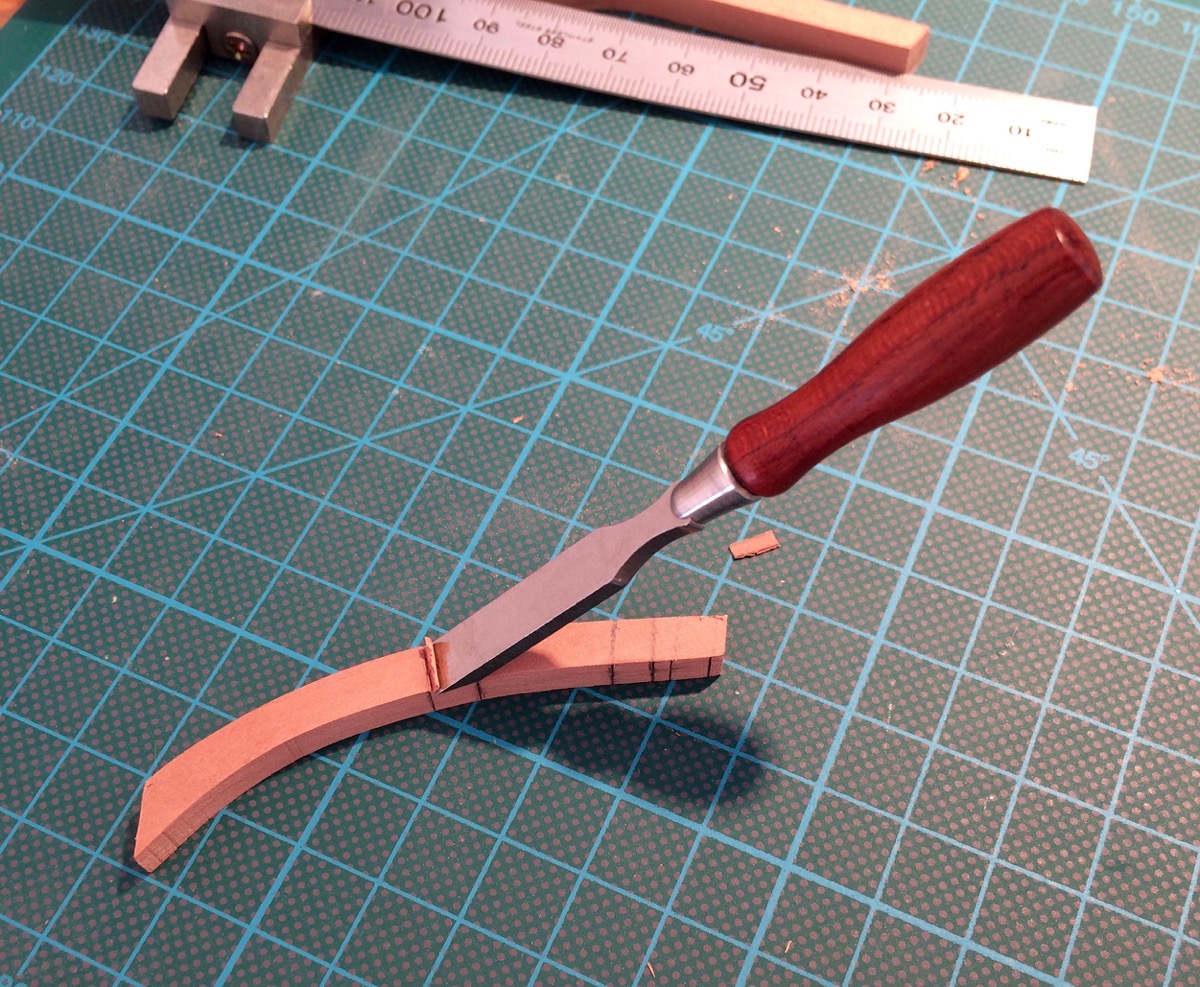
First attempt was an epic failure. Tip: do not put small pieces into the thickness planer - they might rotate and be chewed by the planer blades. Ouch!
Practiced with small chisels (will need the chiseling skill for deck framing anyway):
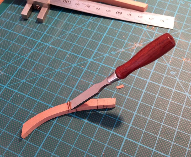
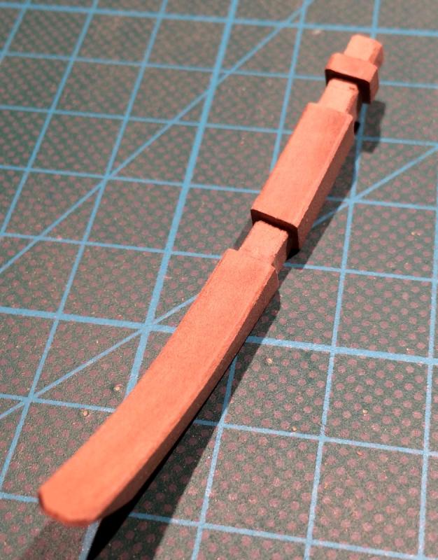
Result:
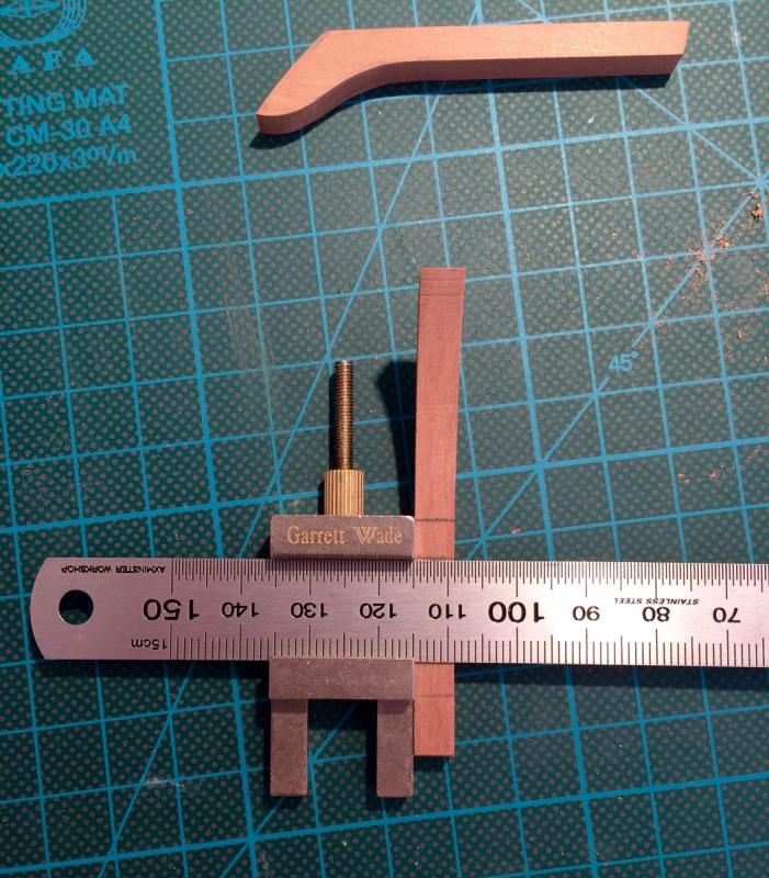
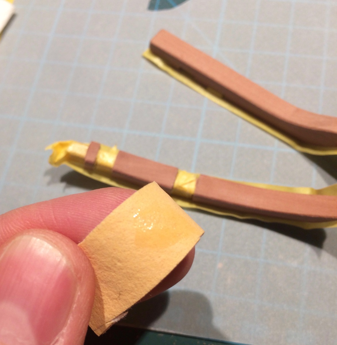
Now applying tung oil. Masking is not very effective with oil, since it sips through the wood grain, but better than nothing.
Where possible, was using a window cleaning cloth to apply the oil:

Otherwise, small brush is also fine (need to wipe with a cloth later):
The oil is surprisingly forgiving to different application methods.
Freshly oiled pieces:

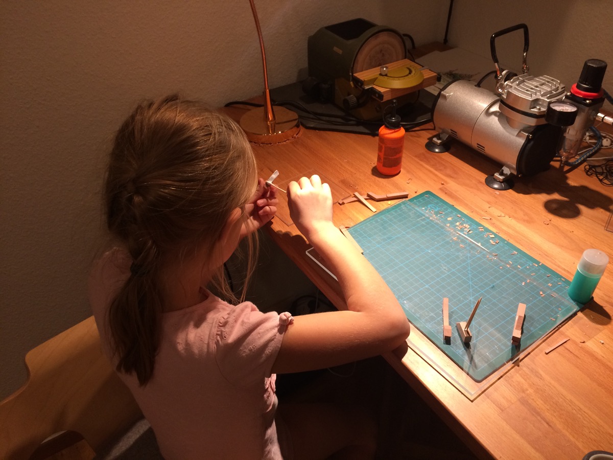
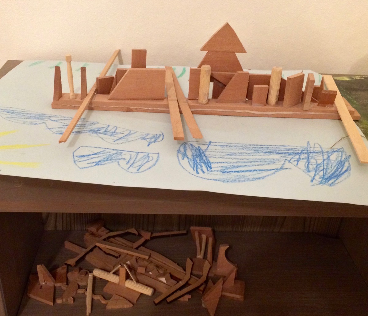
The last part is a cleanup and recycling of the scrap pieces - my daughter helps with that. She has a good enough imagination to build stuff out of scrap and then play with it


For example, this was her salvaging the frame blank cutoff pile a year ago. She says it is a city skyline with a giant cristmas tree on the main square:

-
-
The comments made me blush

But it is really because of MSW - there are so many great build logs to learn on, especially the ones where people share the process, show how a certain part is done, different tricks and jigs, etc. That is one of the most fascinating parts of this hobby for me. Some people can do magic with just a few tools, sharp blade and a chisel. And steady hand and an eagle eye.
But some come up with a clever jig that does not require a sharp eye or hand skill, but will produce a stable and good result. This is engineering at its best. Such build logs and Remco's motto are an information treasure!
That is why I am always pedantically documenting the build process. It might be very trivial and boring for some readers, but could be interesting for others.
- cog, mtaylor, Stuntflyer and 5 others
-
 8
8
-
It is just perfect in all aspects!
- aviaamator, mtaylor, PeteB and 1 other
-
4
-
-
Where will you display your craft's result ... You should give people a chance to see it
At home, so far. I am greedy
Even if I will decide to donate it to the museum - do not think they will take it. Stockholm maritime museum has more models in their collection that they want to display. Some of them are top notch, way better then mine, but still not on display. Carl, but you are always welcome to see it, you live fairly close by 
Good evening Mike.
I have to agree with you on the scrapers. Your work looks amazing.
Hope you enjoy them! They are not smooth enough for the finishing work, but nothing can compete with tiny xacto blades for finish scraping. No nicks or dents, super clean surface left
Super work on the Keelson! With all of those joints, angles, edges, etc, it's almost as if you've created the perfect blend between craftsmanship, engineering and just sheer talent!
Patrick, thanks a lot! You hit the nail - it is a lot about engineering, I am really attracted to this period and style because it shows a pretty complex, but beautiful curves of the ship hull. Shipbuilding industry of that centuries was closer to a large-scale workmanship, with aesthetics being a big part of it.
-
Thanks a lot again! It is always a pleasure to see the new posts here
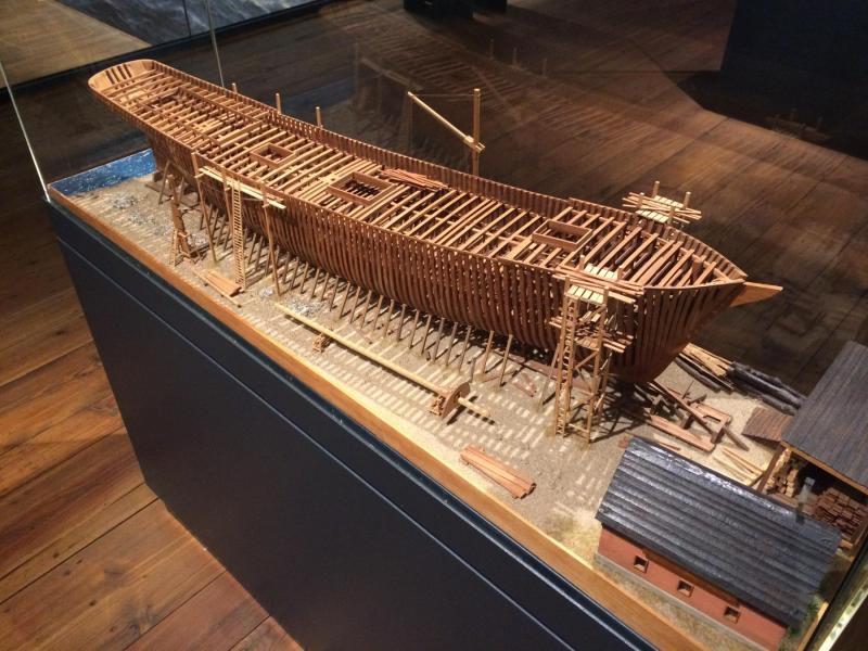
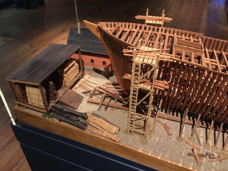
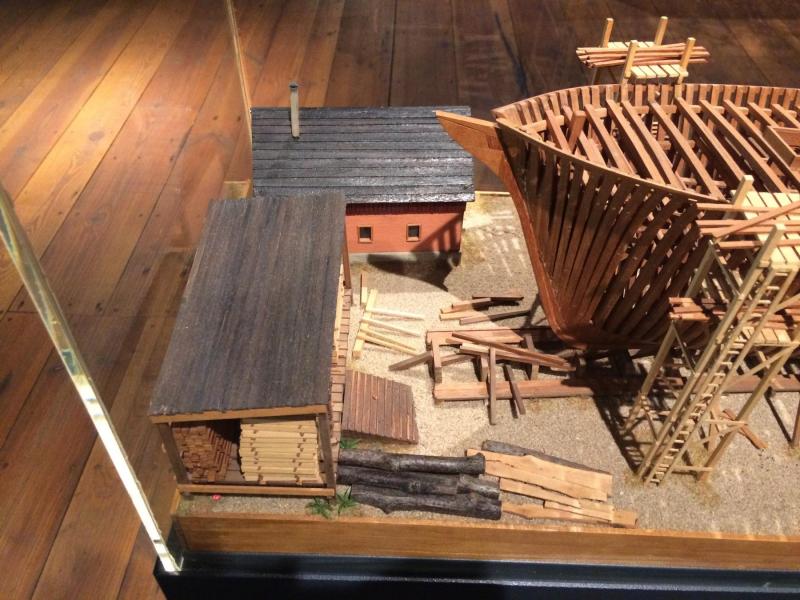
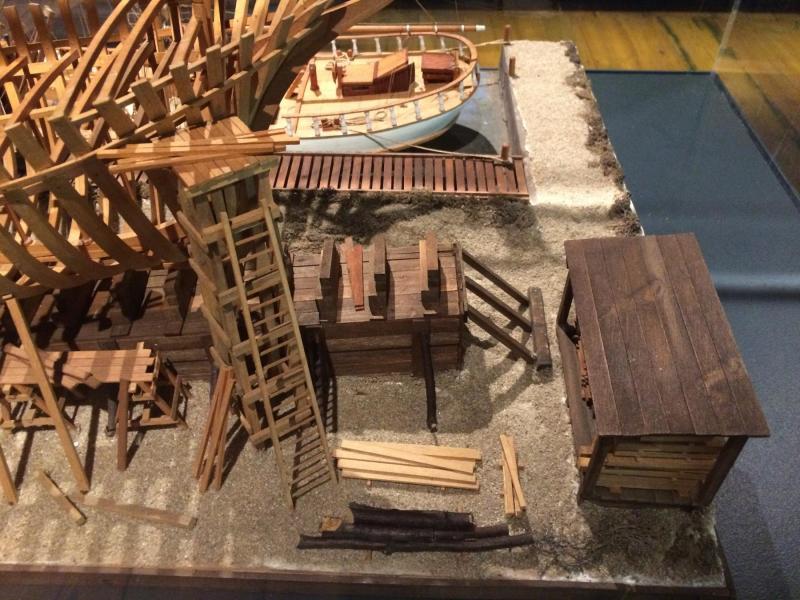
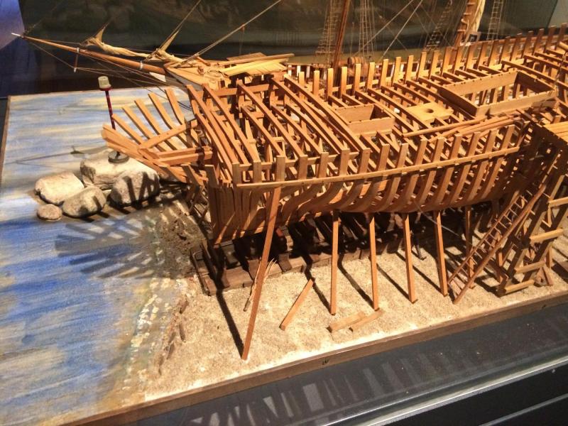
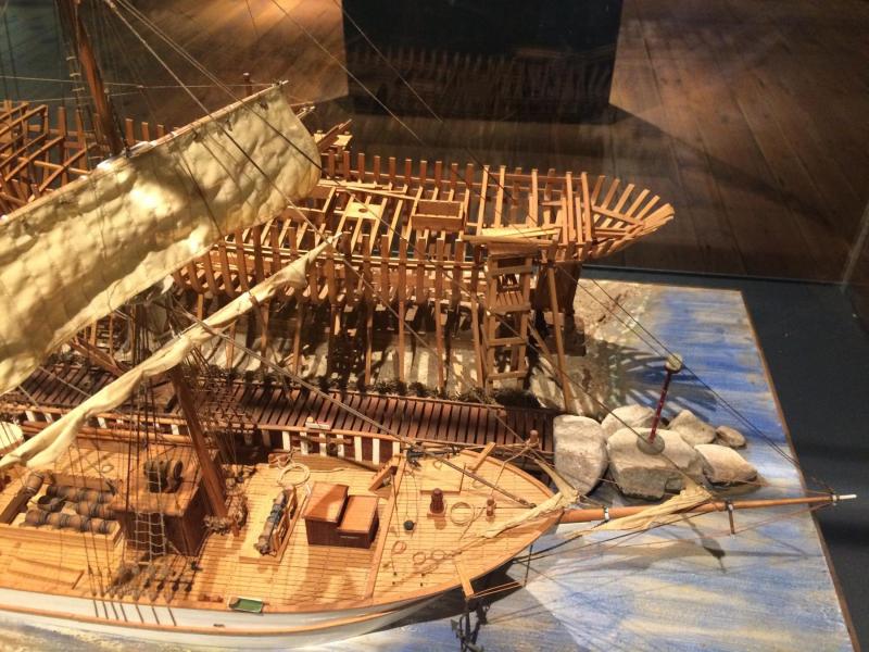
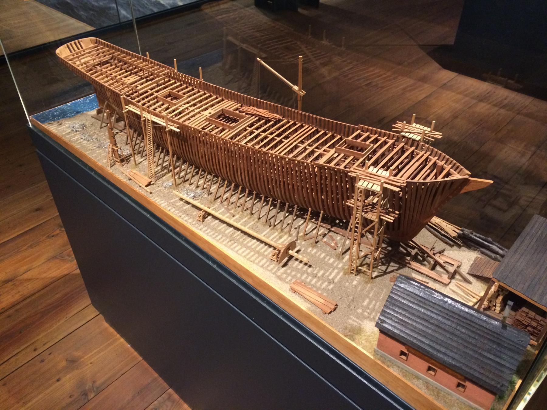
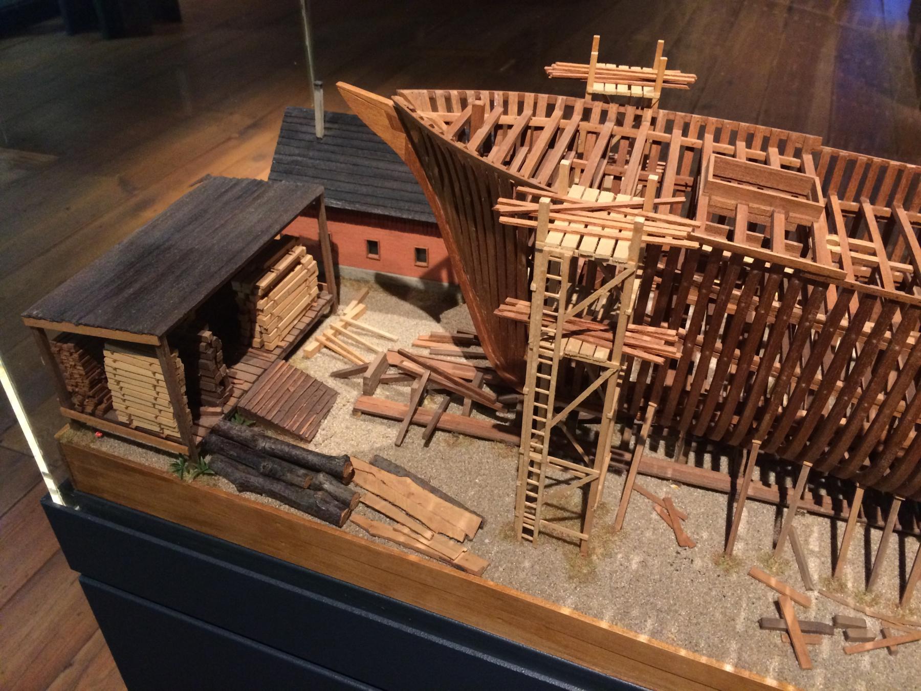
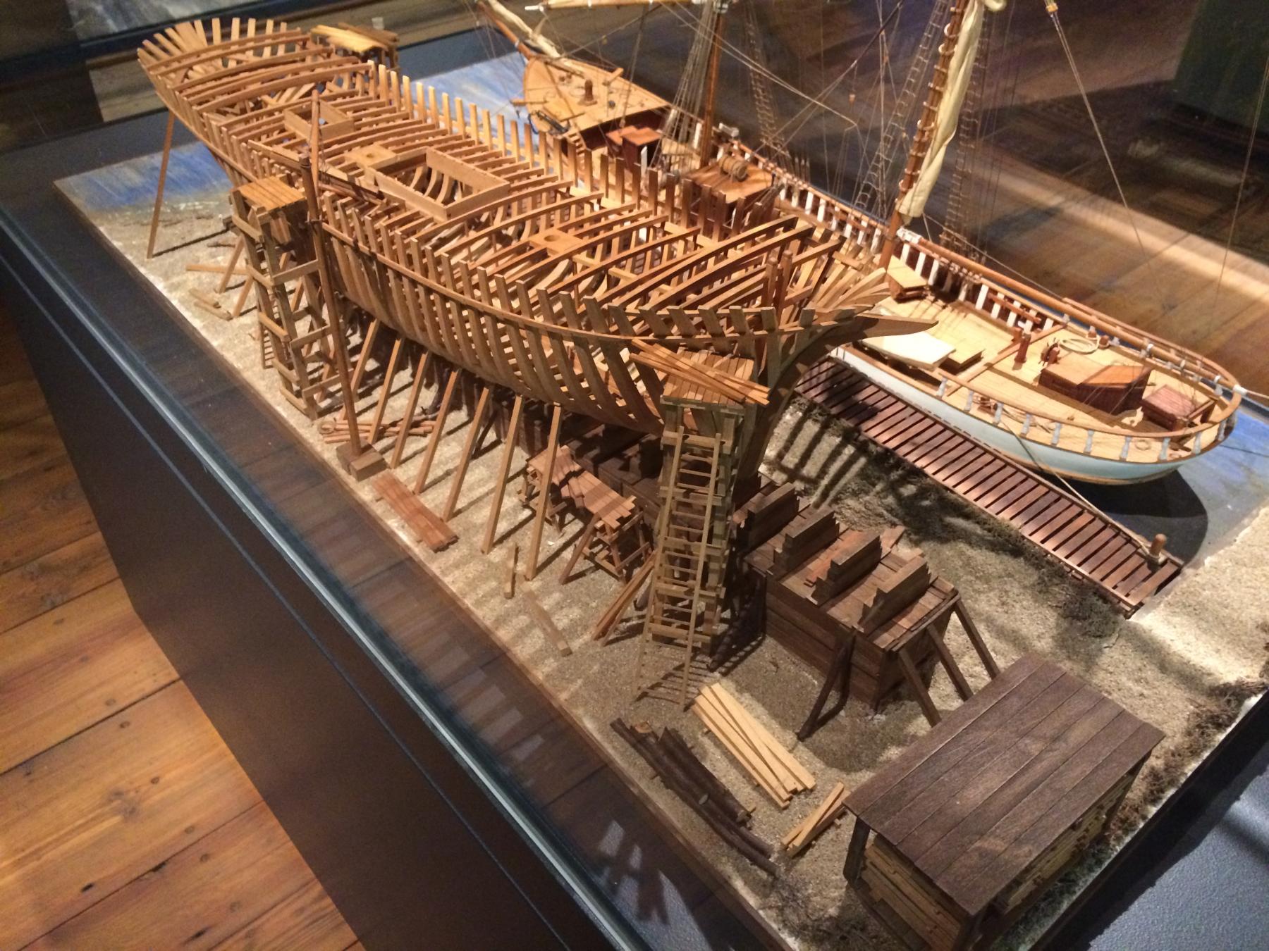
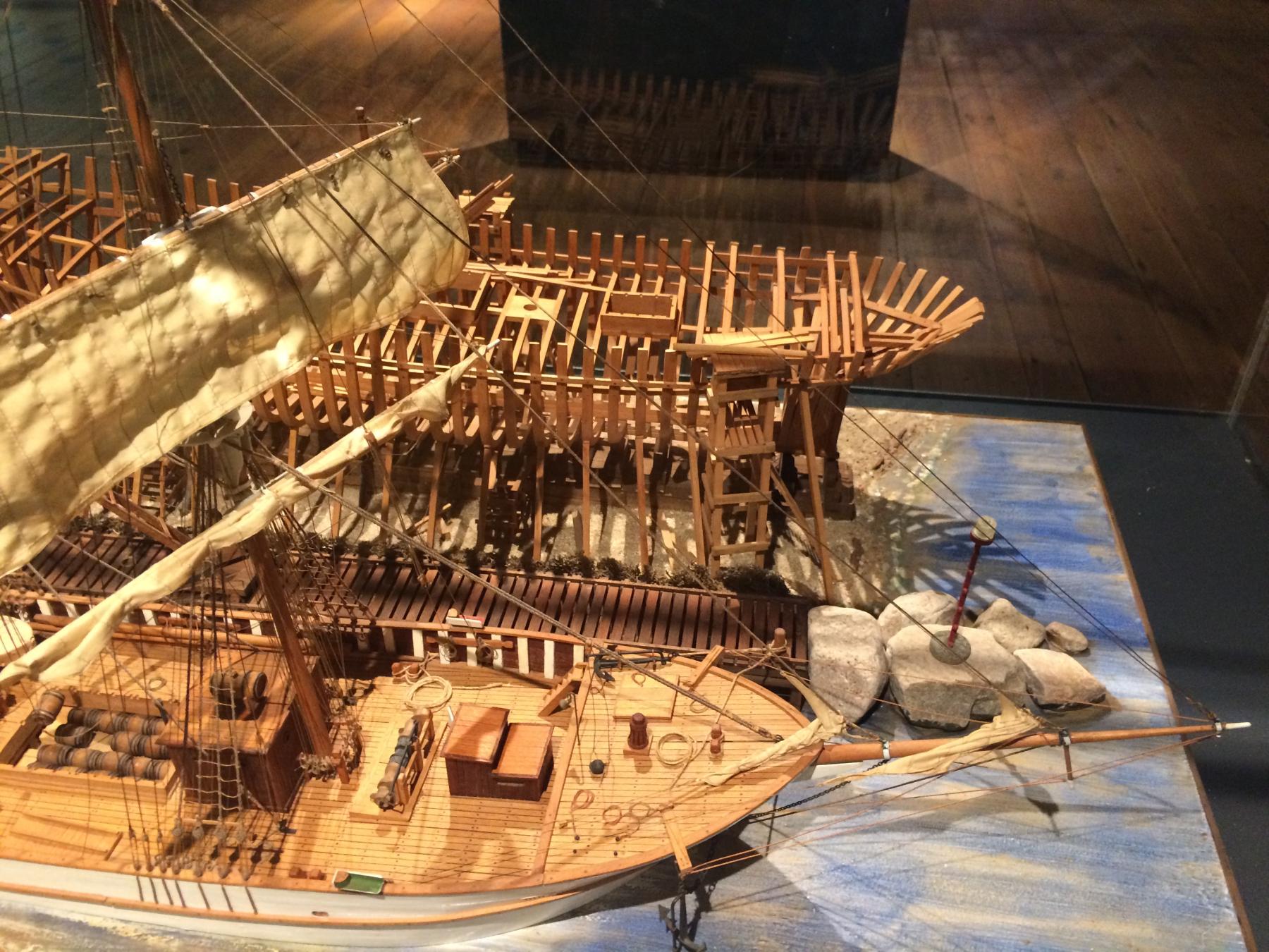
Speaking of the dockyards - sorry for hijacking your topic, hope you do not mind a few photos from Hamburg maritime museum:

- popeye2sea, Tadeusz43, mtaylor and 7 others
-
10
-
Yes, that is comforting - once I reach the top decks - I will already learn enough on mistakes done in the bottom of the hull. Nobody will see the deep parts of the hull anyway

I would be super happy if anybody will ever look deep enough into the model to find a loose joint in the keelson.
- Omega1234, Wishmaster, druxey and 3 others
-
6
-
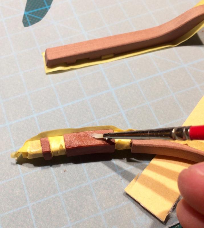
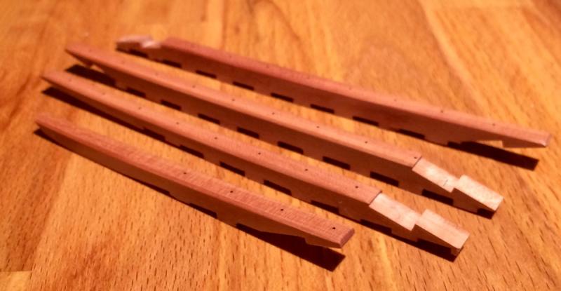
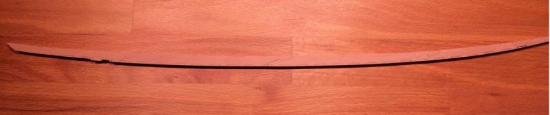
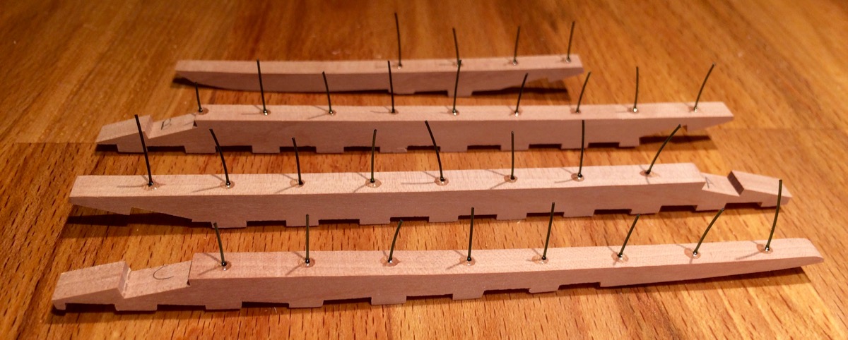
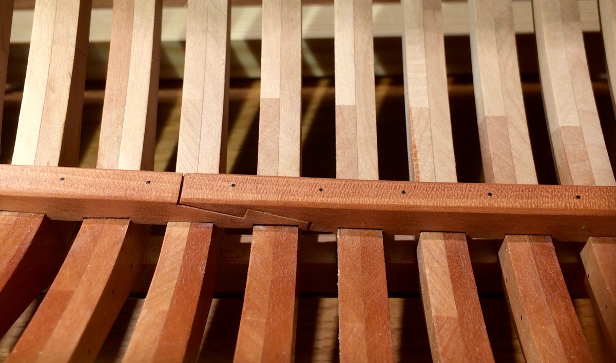
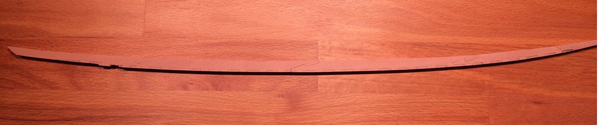
Keelson is done.
Bolts are simulated with black monofilament that is glued with gel CA.

Then CA is sanded away and the wood is scraped with xacto blade to the desired finish:
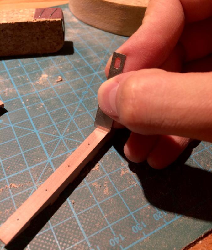
I start to like scraping more than sanding with fine sandpaper - paper leaves some super fine sawdust in the wood pores, while scraping removes it and leaves a better finish.
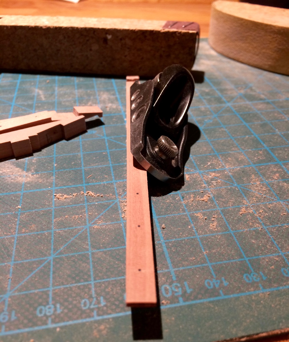
Edges are chamfered with the plane and fine shaped by scraping (because keelson is a bit curved, plane is not perfect for it):
Tung oil applied:
Applied the oil before gluing - it would be really hard to reach the corners between the frames and the keelson when keelson is installed.
I find the oil really forgiving - you can scrape some parts after the installation to make sure they fit perfectly, and then re-apply oil there - it will perfectly blend with the previously finished areas. Very forgiving finish.
End result:
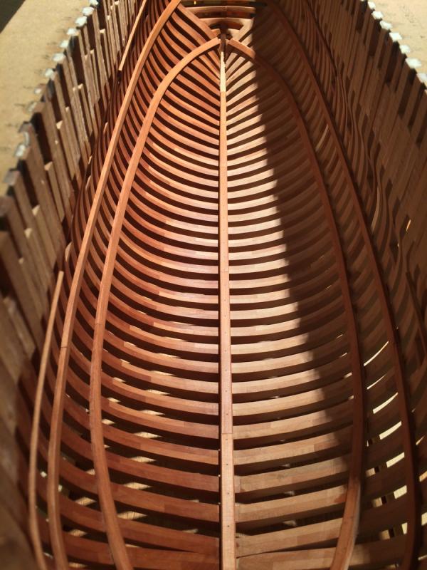
I am not happy with the fit quality - everything was perfectly fitting when not on a hull, but on a hull the join angles got a bit out of alignment, leading to gaps:

Will spend more time fine-fitting on the hull next time!
-
-
Very fine wood, I am using the same pear from Arkowood, it finishes nicely and is perfect!
Please keep it coming!
- aviaamator, mtaylor, Omega1234 and 1 other
-
4
-
Grant, I just realised that I am an idiot - thin knife should fit if you poke it from the outside, not from the inside of the hull.
Thanks for the comment that pushed me in the right direction. Will re-mark the remaining pieces of the keel, should save some time for fit-and-cut iterations.
-
Grant, I have a scriber, but the sharp angle between the marking tool and frames and keelson makes it really hard to use anything except pencil.
Ideally some hook-shaped scriber could be used, but I was too lazy to make one just for a single use.
- Captain Poison, Omega1234, Canute and 1 other
-
4
-
Great accuracy, easily the best viking model out there!
-
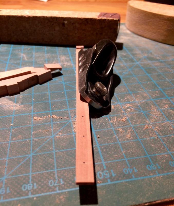
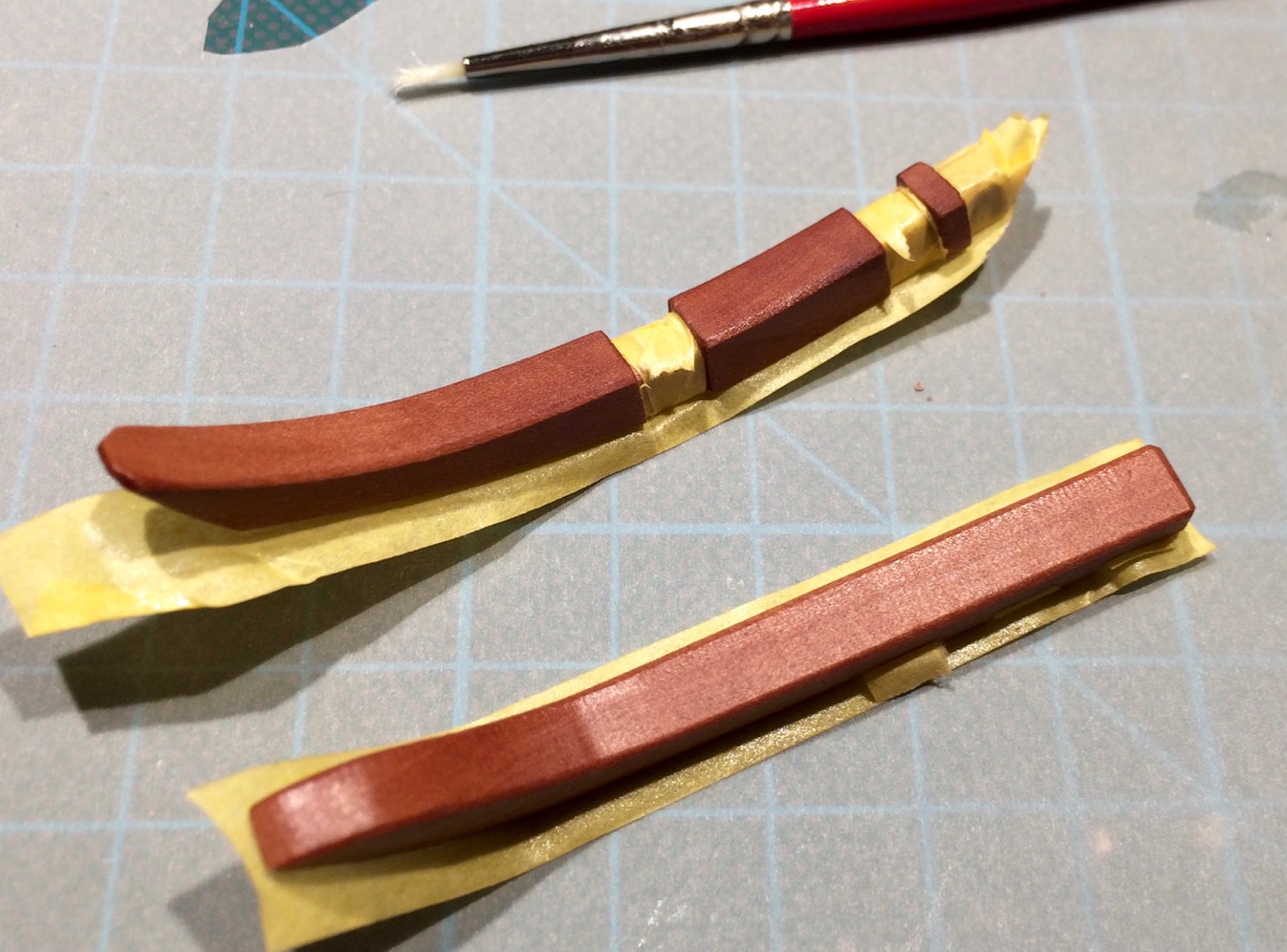
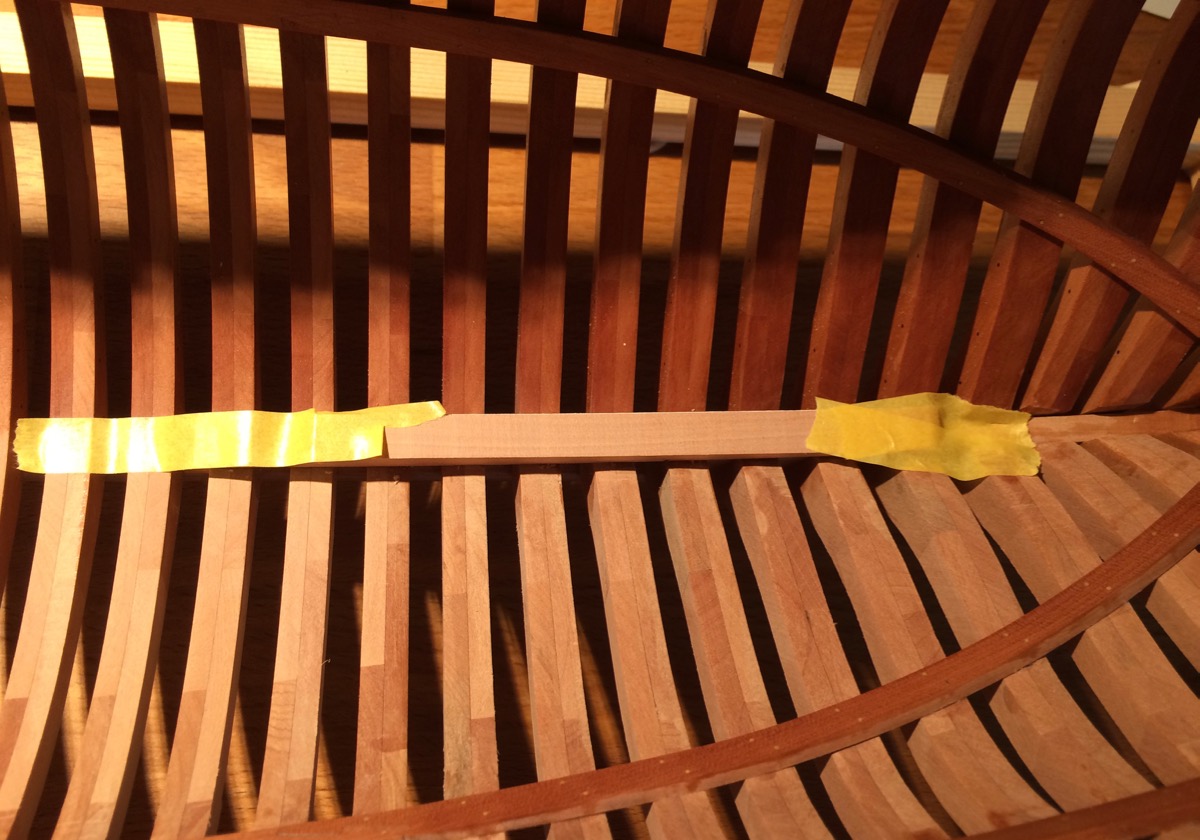
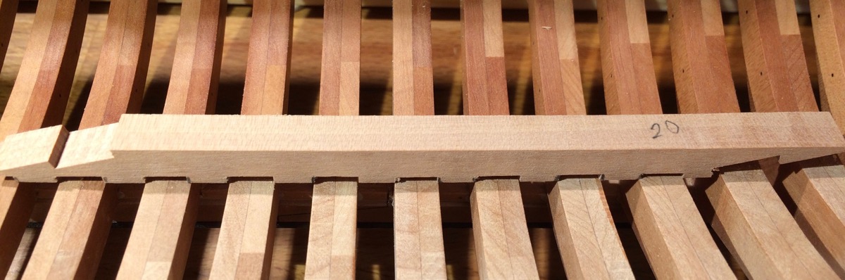
Working on the keelson.
Decided not to rely on the plans due to possible error here and there, and fit it to the hull instead.
Fixing the keelson parts to the hull with masking tape:
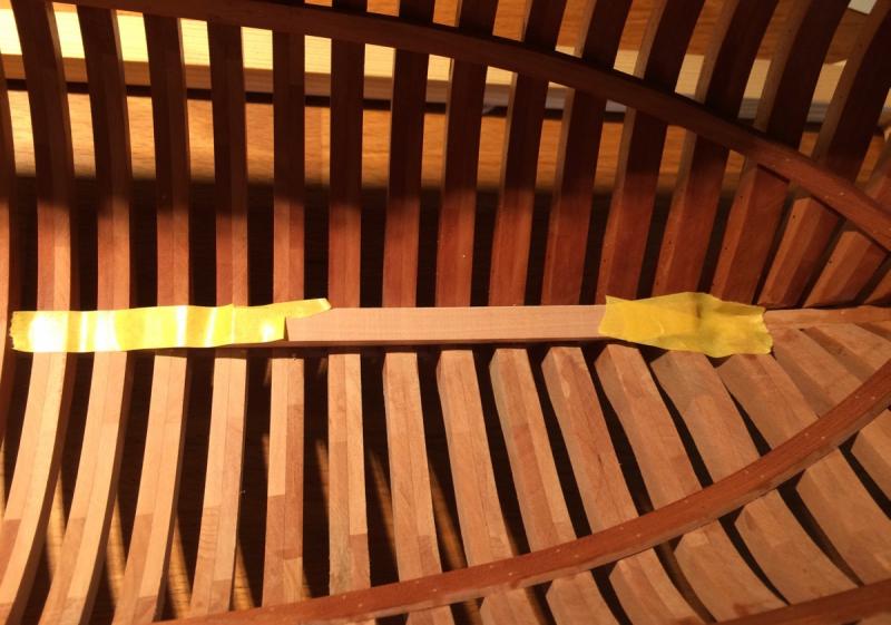
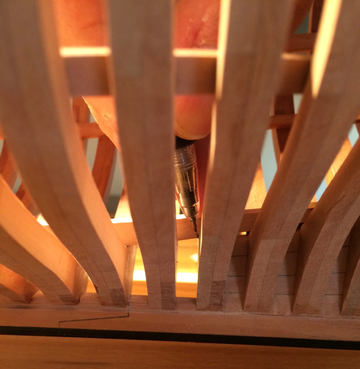
Marking frame boundaries:

Keelson markup completed:
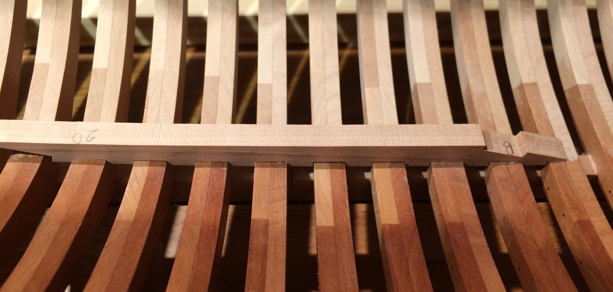
First fit after milling, some notches are not wide enough. Three iterations on a mill were required, because these pencil marks are not precise enough (hard to get the pencil right, the angle was awkward):
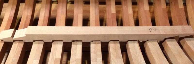
After the fitting. Will need to make some notches deeper to avoid gaps:

Now rinse and repeat!
- davec, CiscoH, Robin Lous and 23 others
-
26
-
-
-
Pardon a few questions, but is it already glued, or you will remove the paper templates and glue everything together later?
How are you going to fair the inside of the frames? Looks like a lot of material to remove!
Watching with interest, quite a new method!
- mtaylor, aviaamator, cookster and 2 others
-
5
-
-
Few cents: I am not sure if simplification is a part of the style (except framing). I thought it is more of "let's leave some details up to the builder".Bill,
"Hahn style" involves a lot and the modeler can go with as much or as little as they wish. As Mike pointed out, there's stylized framing, the jig for working upside down (and also right side for the interior). There's also minimal if any carlings used during decking process. No knees, etc. Simplified keel, stem, and stern deadwood. I'm thinking there's a bit more but I'm in the middle of a "senior moment" on those points.
Bill, here is a link to the Oliver Cromwell plans preview from Lumberyard website (the preview is distorted and not suitavle for building, you need to purchase real plans to build): http://www.dlumberyard.com/Plans/cromwell.pdf
As you can see, some things are simplified. Like Mark mentolned - knees, carlings, deadwood, stem, stern,
But nothing stops the builder from reading up and making a correct version instead of simplified one, like I did. It will not change the "style".
However if you change the framing style - it would not be a Hahn style anymore.
But it is really a fuzzy term. Hahn was "anti-purist", so hope he would not mind people deviating from his plans even if building from them
- Omega1234, Canute, Mirabell61 and 1 other
-
4
-
-
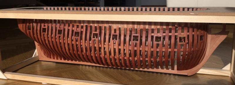
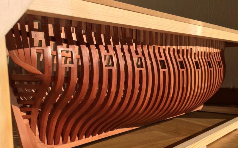
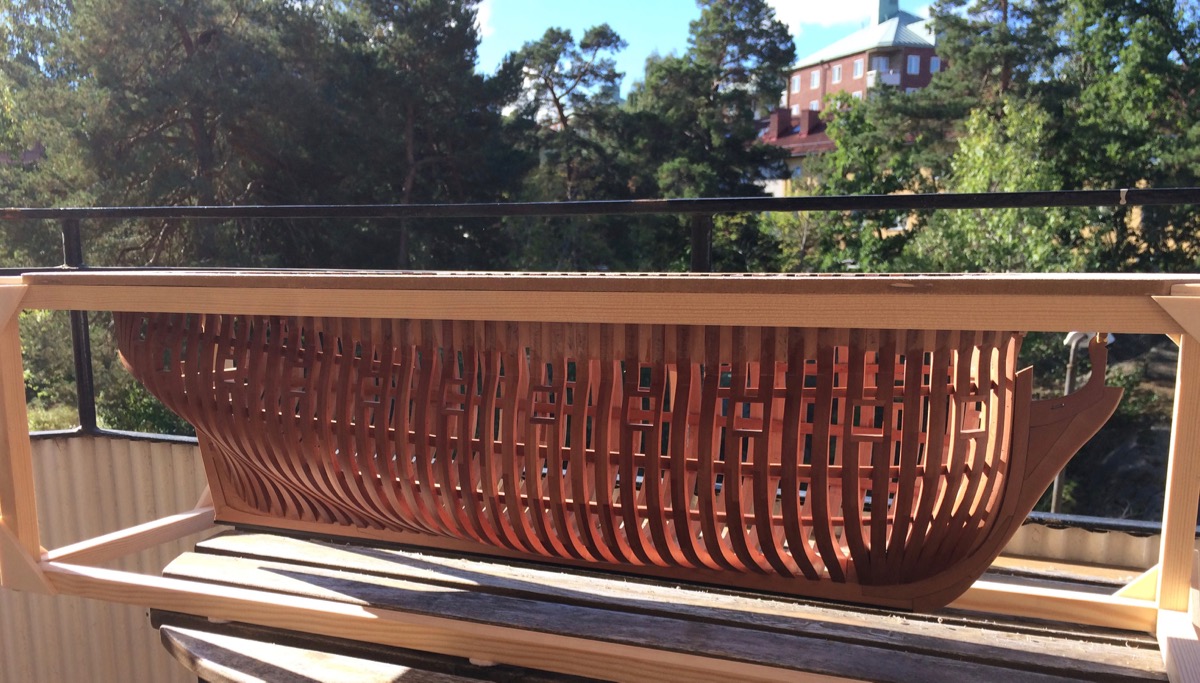
Some "build snapshot" photos. Tung oil finish is especially beautiful under direct sunlight. It is such a pity that it is a not a good idea to display the model in the sunny place
Damn physics!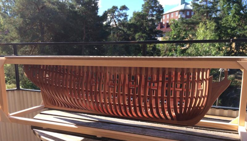
- Wishmaster, Erik W, Omega1234 and 31 others
-
34
-


Beavers Prize 1777 by Mike Y - 1:48 - POF - Hahn style
in - Build logs for subjects built 1751 - 1800
Posted
Druxey, I am kind of worried about oling the deck framing (beams, karlings, knees, etc). Once assembled, it would be hard to properly oil all corners and impossible to reach the underside of the deck. But if I oil before assembly, before cutting the mortises - then oil will penetrate some parts completely (since they are quite thin), making the glue bond too weak.
So far the plan is to oil the underside only, then glue everything in place, and then oil the sides with brush and top side with a coth.
Unfortunately all build log skip the finish application part, so no experience to refer to
Would really appreciate some advice!