


Mike Y
-
Posts
1,437 -
Joined
-
Last visited
Content Type
Profiles
Forums
Gallery
Events
Posts posted by Mike Y
-
-
Would be great to raise that 25 page limit for the pdf exporting module. I am pretty sure that this limit is artificial
 It might hit some memory limits on the server if trying to export a really big log, but only if that module is implemented in a really suboptimal way. Hope it is not!
- J T Lombard and robin b
-
 2
2
-
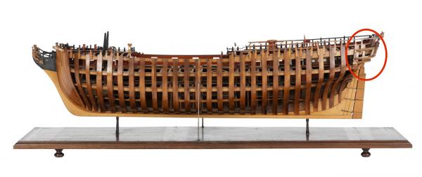
Nice work on those counter timbers. And after all that work, almost none of it will show!
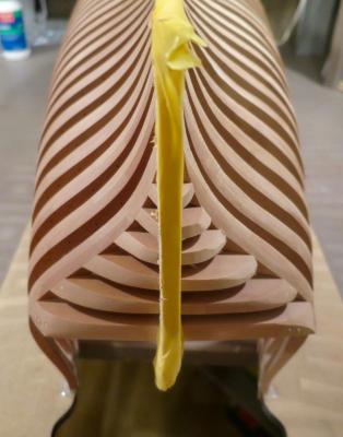
Thanks! But actually, it would be fully visible.
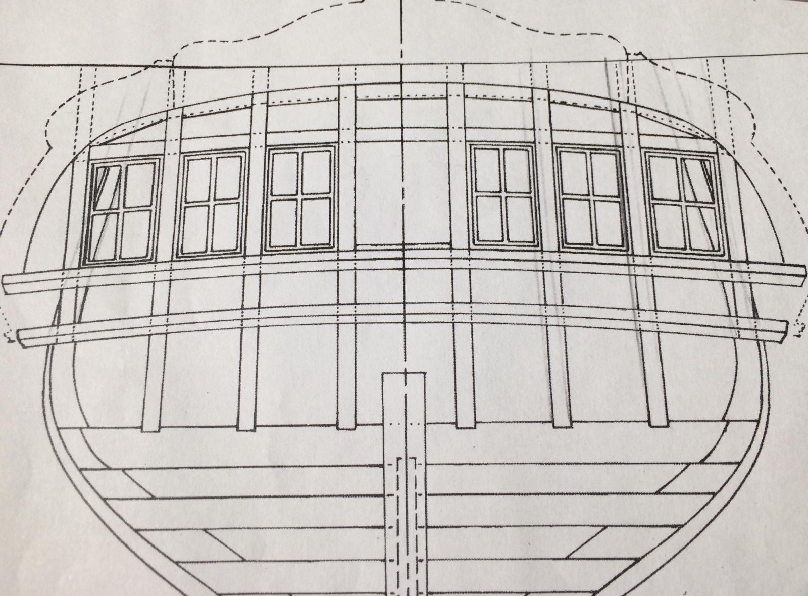
I will leave one side fully unplanked, which means that half of the counter timbers would be exposed (also with some skeleton of the quarter gallery). Like this:
- Canute, albert, Seventynet and 8 others
-
11
-
-
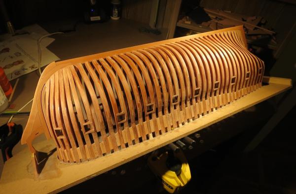
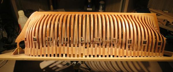
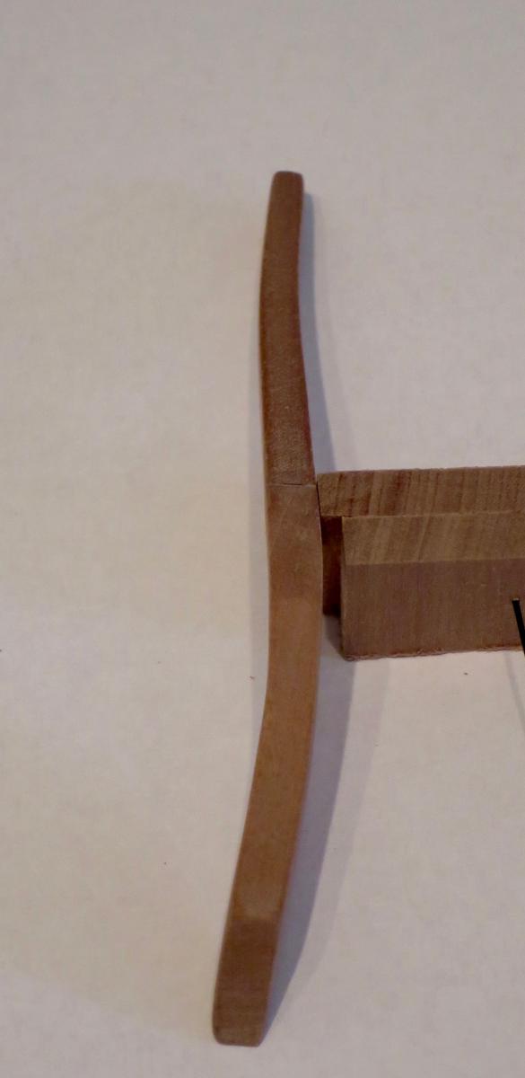
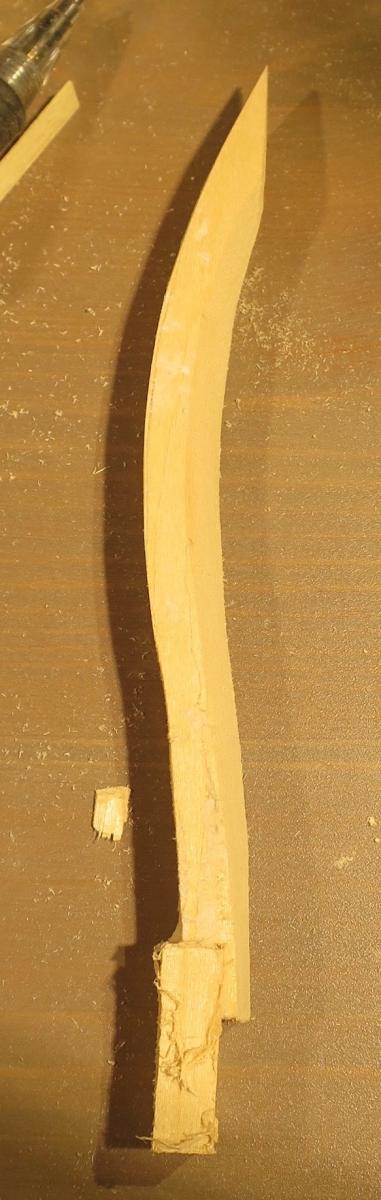
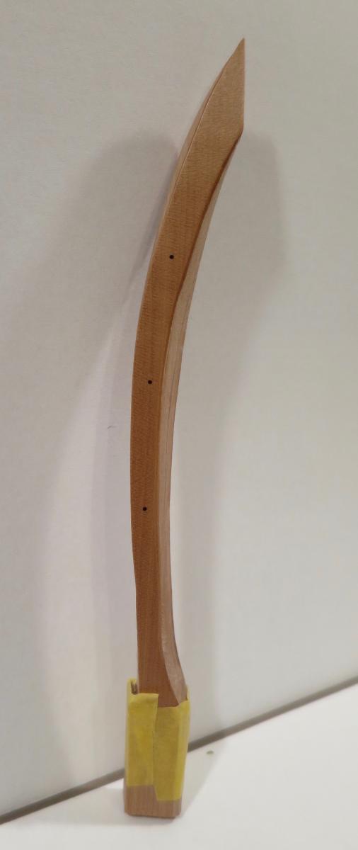
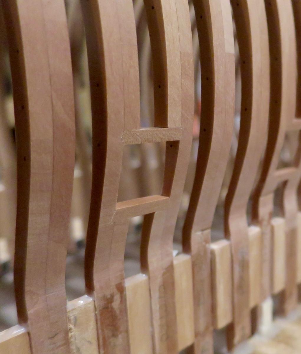
Side counter timbers are fun!
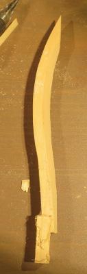
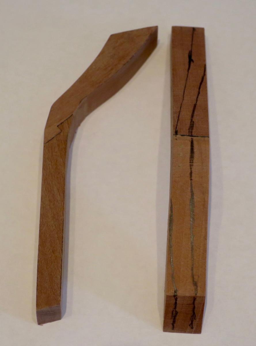
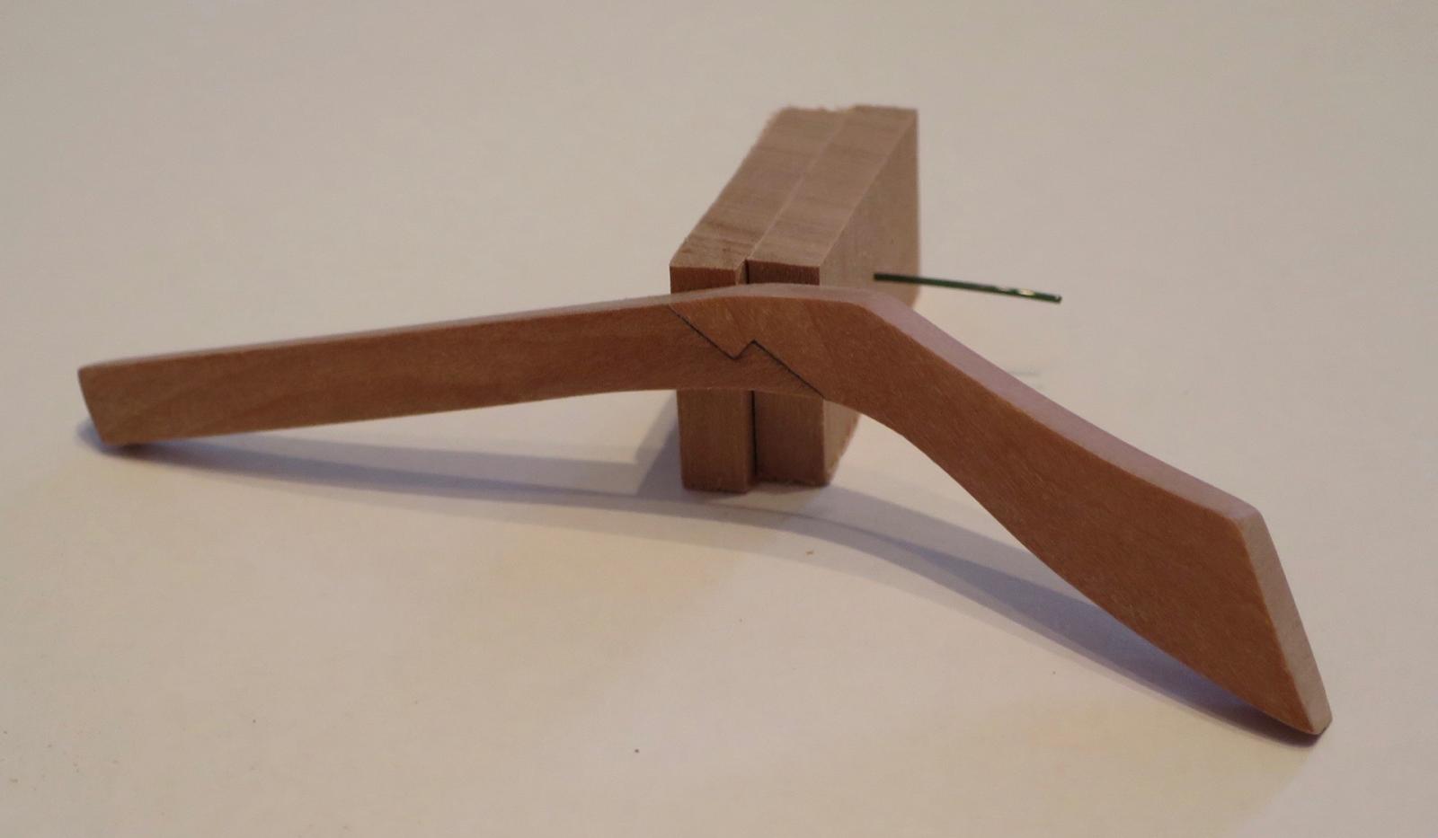
Starting with an oversized piece, made of two pieces each:

After cutting and sanding:
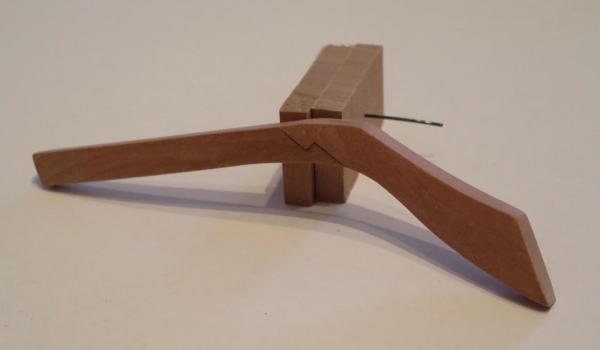
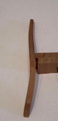
Installed, with a really oversized wing-like timbers:
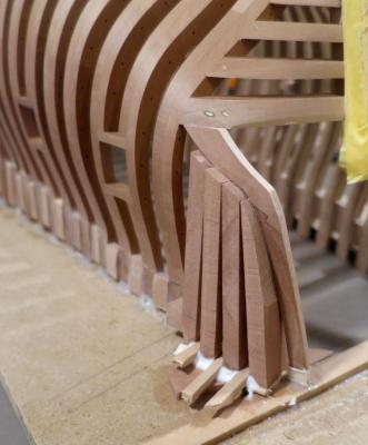
Now need to cut them to shape right on the hull, fair and add some nice spacers

- mtaylor, gjdale, paulsutcliffe and 22 others
-
25
-
-
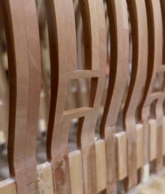
Installed "hawse timbers". There were three options
1) Install a filler piece. Meh!
2) Build hawse timbers as they should be, as TFFM describes it. Opened the chapter about it, realised I also need bollard timbers. And I was supposed to do that without any drawings and patterns, because Hahn omits that detail as non-important
Also, it will look weird - tightly spaced timbers at the bow, and evenly spaced simplified framing at the rest of the hull.
So - next time, next model
So I decided to go with option #3 - install one more frame that will look like a cant frame, and will follow the style of other frames.
Since there are no drawings for that, started with template. Used that mushy extra-soft basswood that is supplied with Longboat kit - it is better than cardboard for that purpose, and shapes easily with any tools.
Ended up with this beefy template:

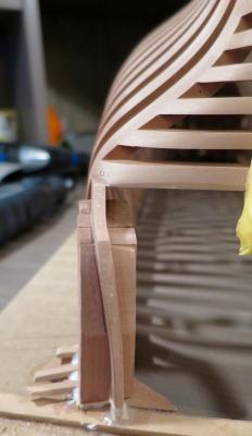
After lots of fitting and fine tuning, resulting hawse timber / extra cant frame ended up installed:

Now making a side counter timbers. They would be built in TFFM way, because I do not like the way Hahn suggests to make it - with counter timbers installed 90 degrees to the ground, instead of following the curve of the hull.
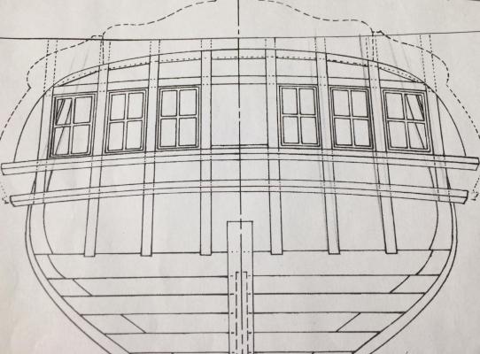
Huh, really?
Going to do it this way (thanks Toni for a very clear photo in her Atlanta build log!)
-
I can only guess how long it took to fine tune the keelson! Looks great!
- giampieroricci, kees de mol, mtaylor and 1 other
-
4
-
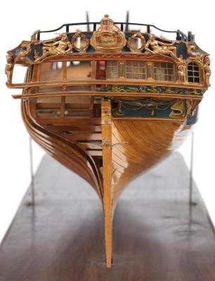
Oh wow, now it is clear how huge the model is! Have you weighted it?
Also, what is your feedback on that LED lights in the display case? I was always worried that a cold white light will make model look more flat and pale than it really is. But your photos show a nice deep rich color. What are those LEDs? Would appreciate some information!
-
Real eye candy and a masterpiece!
- CaptainSteve, mtaylor, Siggi52 and 1 other
-
4
-
-
The best place to buy it in Europe is amazon.de, never saw it cheaper.
It is a good sander, very quiet. But mine was with slightly curved table, I replaced it with a wooden one. However, Proxxon support is good, they will ship you another table if that problem will happen for you!
-
-
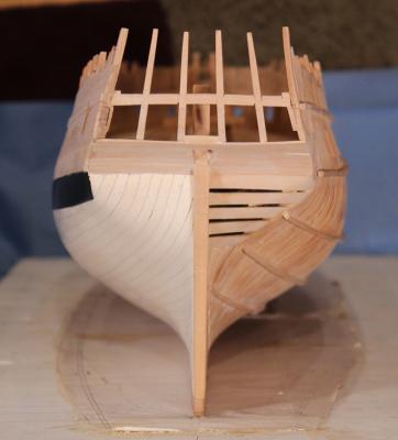
Nope, the port side (that would be fully planked) is not shaped or faired at all. I specifically made that last photo to show the comparisonVery nicely done Mike!
Have you finished working on the port side transoms?
Alan
The port side transom is currently ugly as hell!
-
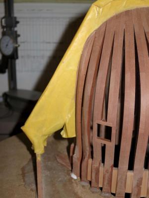
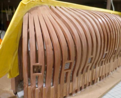
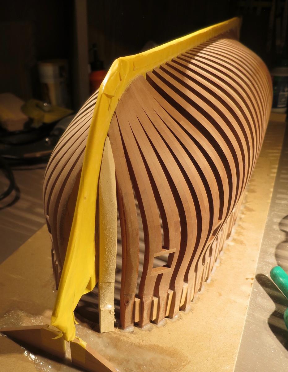
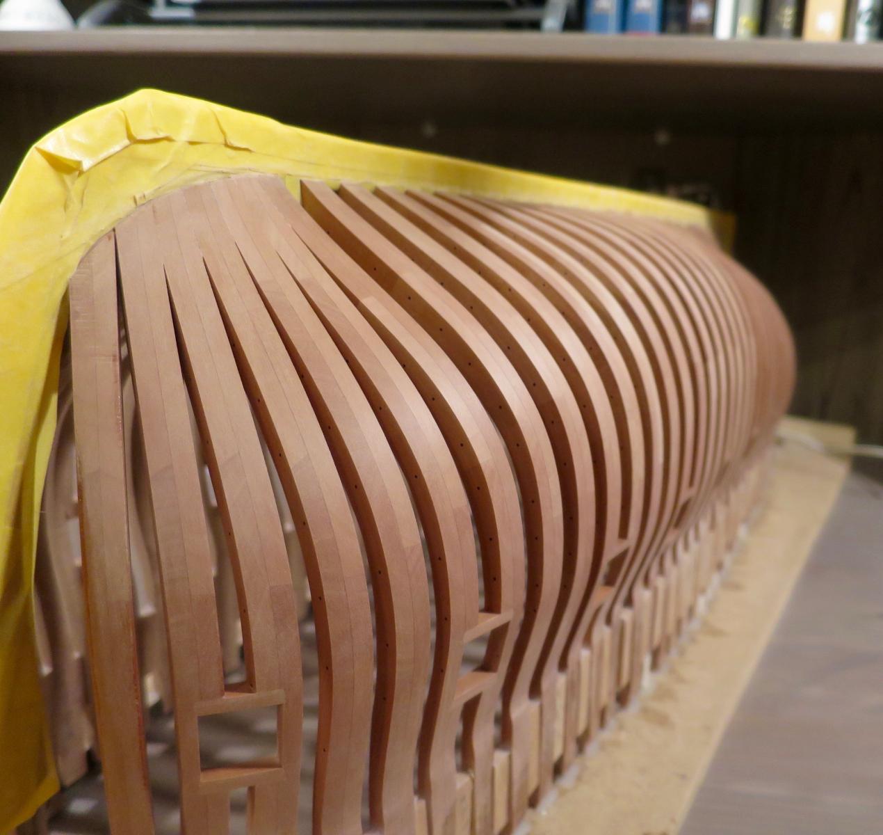
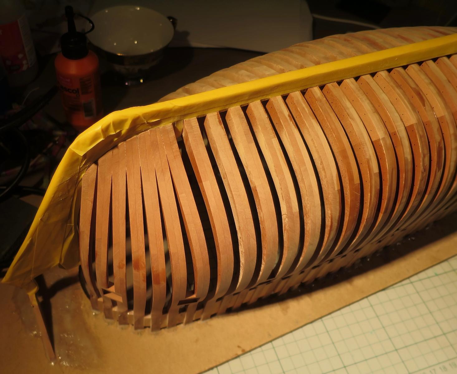
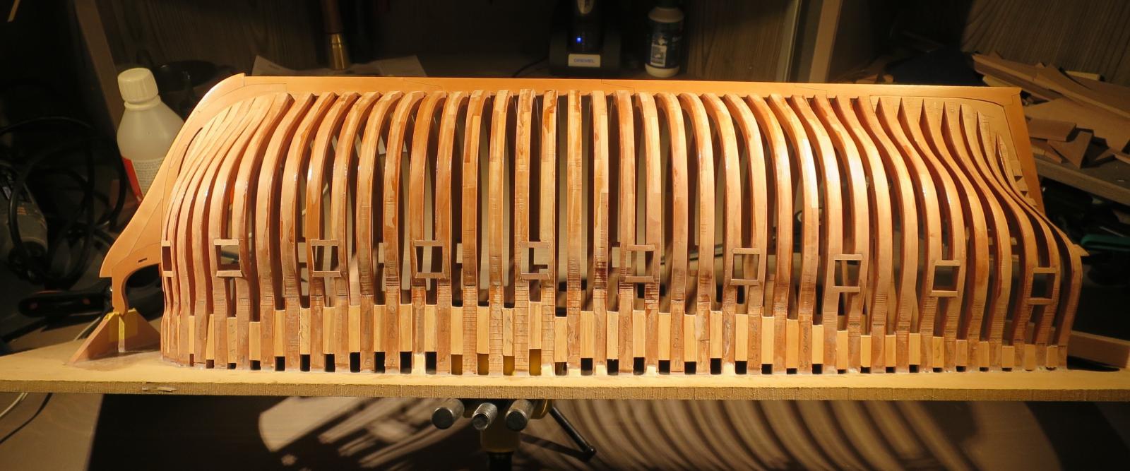
Finished the most risky part of the fairing - the outer surface of the side that would be opened.
Lesson for the future - if you add the bolt simulation - add another millimiter of margin to the frame lines, especially on the sides of the hull (it is unlikely that the bottom would be problematic).
Ended up with some really thin sides around the midship:
But overall - nothing is screwed up! Just some bolts that are too close to the edge of the frame, but they are not poking to the side!

No finish applied, and will sand with fine grits right before finishing - apparently, finger marks are very visible.

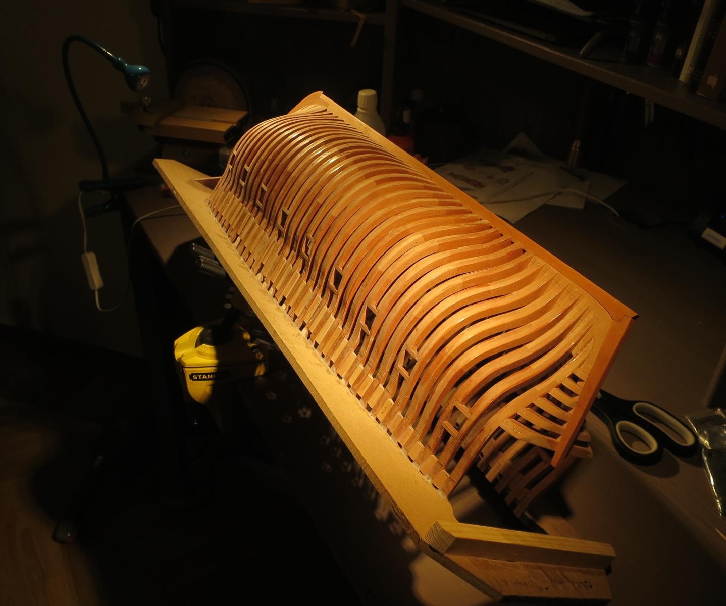
The transom wings required a lot of shaping! You can compare with the non-faired side on the right.
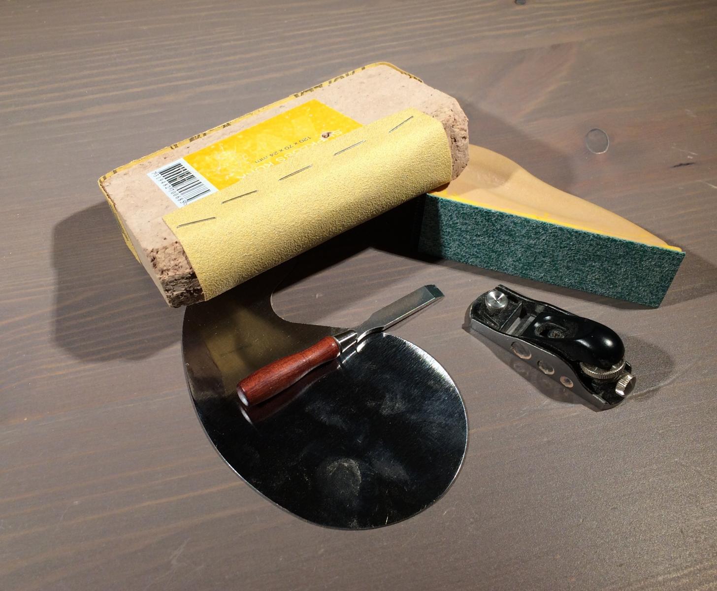
I tried lots of different tools for fairing, but ended up with this set:

Cork block shaped to be round on one side, and remains flat on another. Sandpaper - Mirka 120 grit.
Semi-flexible yellow thingy was very useful when sanding the bow and transom. Right the exact flex! Grit 90.
French curve scraper helped to level the frames, especially in the tight areas. In another areas, miniature chisel was used for that.
Surprisingly, block plane was very useful to quickly even out the frames, to later finish it with the sanding block.
- dvm27, oneslim, Seventynet and 25 others
-
28
-
-
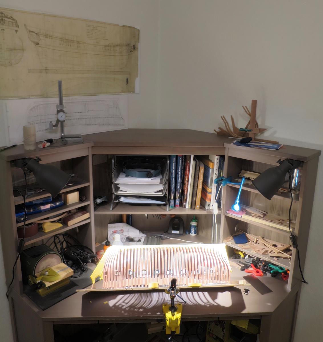
Ended up with changing the lamps every time I need to make a photo
Bright lamps for modelling, softer ones for photos.
Gaetan, thanks for the advice, but it is a living room, so aesthetics matter. I moved from a lamp on the arm to two stationary mounted lamps because they are nicer..
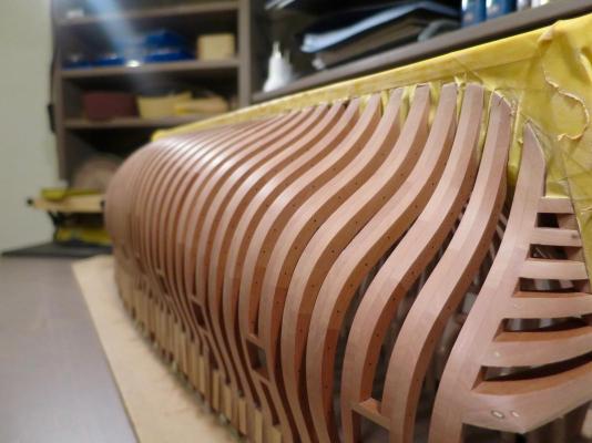
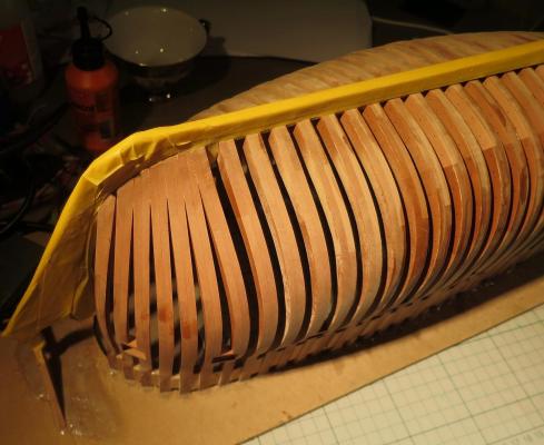
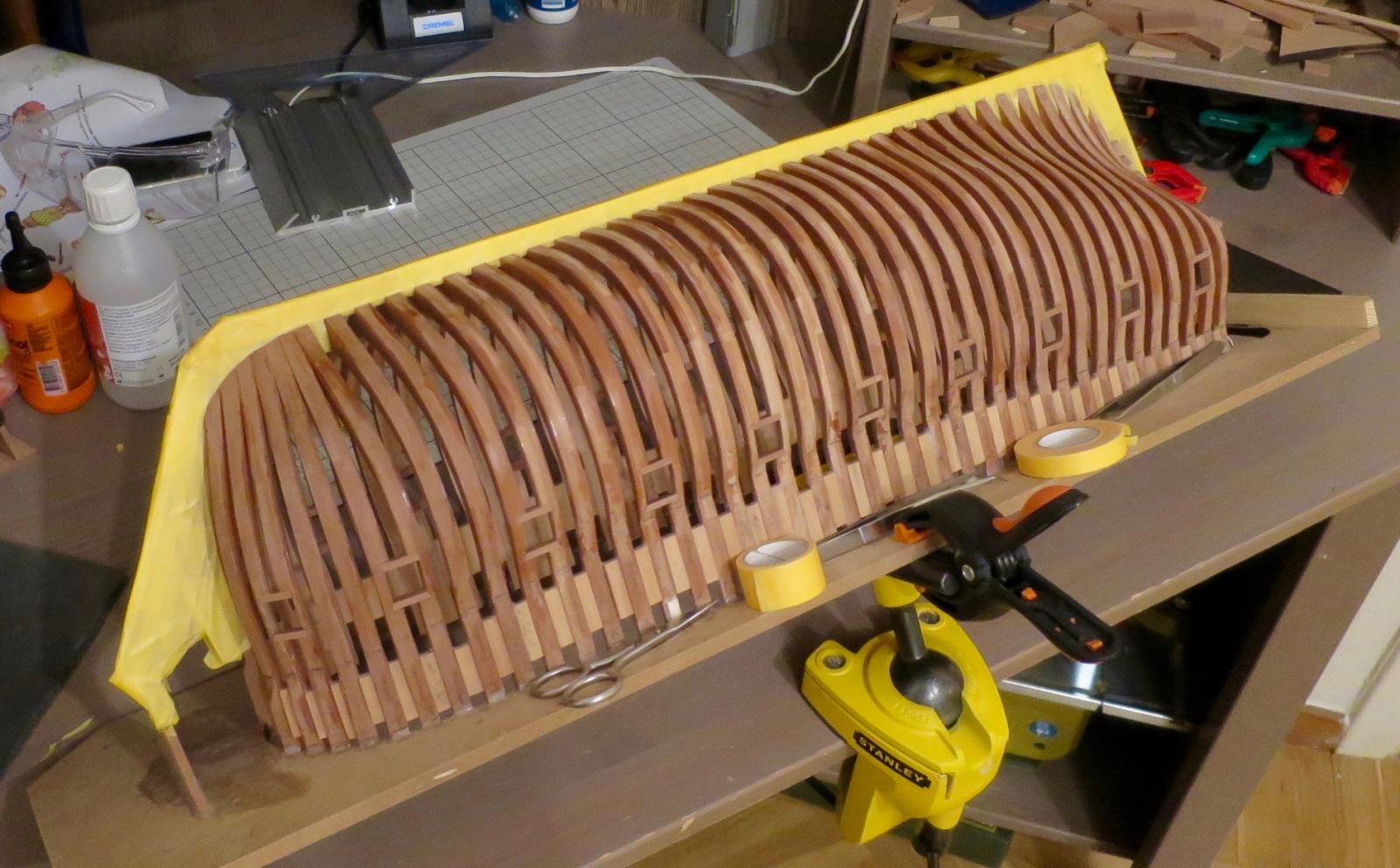
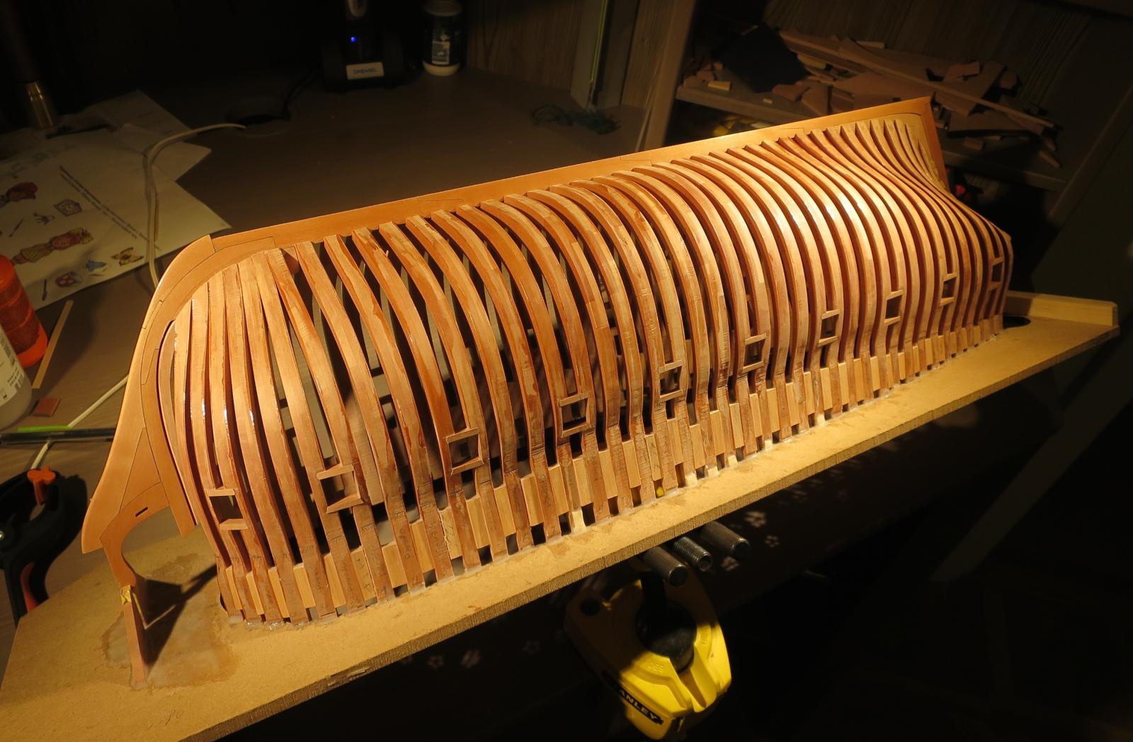
Started the fairing. Some fairies are definitely involved! It is a real miracle, what it does with the hull!
You can probably spot the difference between faired bow and other parts of the hull.
(Please enlarge the photos to see it better)
And a "romantic" version with powerful lamps
This is a very first version, the highest grit was only 240.
Apparently, accidental finger marks are very visible on the faired frames.
Hope to finish the entire hull in a few weeks... Will see how it shines after the high grits
-
-
The "romantic" style of photos is due to the new light setup - two warm spotlights 400lm each installed on both sides of the table:

I will probably just use a weaker lamps (200lm opal shade lamp) to take the photos.
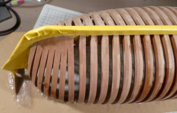
The hull is covered in layers of the masking tape and is ready for fairing.

Getting really used to working on angle, using the vice as a stand to fix the model. Allows for an easy access inside the hull (yes, it is a problem when building upside down), and also easier to work with the sides of the hull.
Dreaming about a lifting table!
-
Thanks Erik!Mike,
Well done! The gun ports look great! Have you had any more low humidity issues? What part of the build is next?
Erik
No new issues, and I unglued one side of every 3th/4th spacer synmetrically on both sides of the hull, so it reduced the hull stress due to shrinkage, and the gaps are now evenly distributed. Should have done that frome the day one
Next is the hull fairing with a very small margins for that. Should have added a bigger margin when cutting the frames!
-
Hoorray, gunports are done!
Practice is the key, the last ports were made twice faster than the first ones
I also changed the lights in the room and working table to a warmer ones, and now my camera switched to some sort of warm mode when in auto. Photos look weird now, need to find how to adjust the brightness settings on the camera...

The next step should be fun - hull fairing! Really worried I screwed up the frame alignment, and I added complexity when installed that "iron bolts" that hold the "timbers" together. Which gives a smaller margin for fairing - bolts can't become too close to the frame edge.
-
-
-
-
Remco, do you mind a question?
I read in your log that you used to dilute the tung oil with white spirit, but now you suggest turpentine. What is the difference between that substances for dilution?
Is it possible to store a diluted oil in some can for months, or it should be stored in the original form and diluted right before the application?


Beavers Prize 1777 by Mike Y - 1:48 - POF - Hahn style
in - Build logs for subjects built 1751 - 1800
Posted · Edited by Mike Y
http://www.dlumberyard.com/sells the plans and a timbering set for it.
However, I ended up buying another wood (from Arkowood), because the wood provided with the timbering set had a major colour variation and defects (if we talk about the wood for frames, other wood was fine), and had a very rough finish, and sanding it to smoother finish was a very tedious and dull work. If you have a thickness a sander / planer - that should not be a big deal though.