druxey
-
Posts
13,369 -
Joined
-
Last visited
Content Type
Profiles
Forums
Gallery
Events
Everything posted by druxey
-
 I've not downloaded or tried this program yet, but it looks quite ingenious and very useful! Thank you for making it available, Kris.
 -
Nice to see progress reports and photos, Greg!
-
Thank you so much, Johann. I assume those punches are custom made by yourself to flare both sides equally. A very neat solution!
-
Superb, as usual. What is your method for making thimbles, please?
-
Ron: Guilty as charged, m'lud. And yes , they had to fish out the anchor by the shank once it was above water.
- 542 replies
-
- 3
-

-
- Sphinx
- Vanguard Models
- (and 3 more)
-
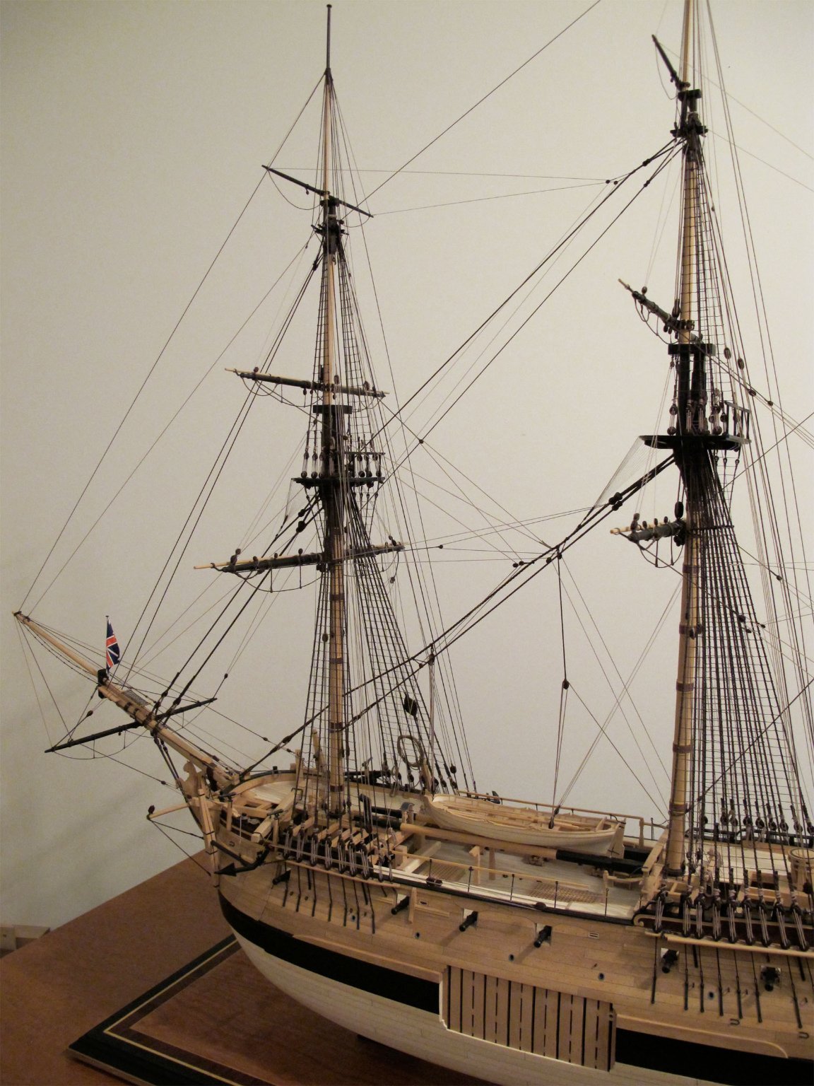
A fish davit was, as the name implies, used specifically for anchor operations. It was replaced by a short davit in around 1800. For raising ships' boats or other heavier items, tackles on the mainstay and yardarms was used. You could not swing items inboard simply using a fish davit. A fish davit is rigged in the accompanying photo as are tackle from the mainstay and yardarms to the boat in the waist. .
- 542 replies
-
- 5
-
-
- Sphinx
- Vanguard Models
- (and 3 more)
-
Certainly one of the more tricky parts of construction. Looking good, but make sure you protect those protruding timbers. It's far too easy to catch and snap them off. Don't ask!
-
Interesting photo of Lowestoft. However, think of the weight of that spar, then having to heave it outboard even more before you can slip the end back through the spanshackle. It would probably tip overboard, the laws of physics being what they are. An illustration in Falconer shows a little less than half the length of the davit outboard, The model photo may be suspect, as so many models were re-rigged or 'restored' over the years. I'm having particular difficulty with a research project, where very old repairs are almost impossible to distinguish from original work.
- 542 replies
-
- 2
-
-
- Sphinx
- Vanguard Models
- (and 3 more)
-
I believe that the spanshackle on the opposite side of the forecastle was used to secure the inboard end of the fish davit. As you haae it, the leverage would place severe strain on the spanshackle bolt, even though it extends down through two beams below.
- 542 replies
-
- 2
-
-
- Sphinx
- Vanguard Models
- (and 3 more)
-
There are some very strange English terms, Siggi! You would probably laugh at my German language skills.
-
Almost right! It's called a 'shankpainter chain'. It is taken around the shank of the anchor when it is stowed.
-
If you have not yet read Kurt Van Dahm's article on shop safety in the current Nautical Research Journal (pp.375-381), please take the time to do so. It may save you a lot of grief.
-
- 8
-
-

-
Terrific work. I love the panelling detail inside the wheelhouse. How much will one be able to see once the model is complete?
-
I'd go with 12", gk.
-
Why masts are square at the top?
druxey replied to Tommy Vercetti's topic in Masting, rigging and sails
Wefalck: um, see response #2! -
For small boats 12" to 18" seems to be the range.
-
There are several ways of making grommets. One way is cutting thin slices of brass tubing (heat-soften it first!) Place the ring on a hardened surface and flare one side using a center punch, if the ring is small enough. Push the ring through a hole in the sail and flare the other side to lock it in place.
-
Fabulous grunging work! But now don't the brick walls look a little too clean? Or are they yet to be dirtied? Your diorama is a pleasure to look at.
- 189 replies
-
- 11
-
-
-
In 18th century terms, a cringle is a rope loop at the corners of and along the edges of sails, either as part of the bolt rope or secured to it. Are you thinking, perhaps, of a grommet? That is a ring of metal fixed within the edge of a sail.
-
Swan-Class Sloop by Stuglo - FINISHED - 1:48
druxey replied to stuglo's topic in - Build logs for subjects built 1751 - 1800
Making paper or thin card patterns for any complex piece saves a lot of wood (and bad language!). Your counter planking looks good. -
Good progress, but had you considered using SilkSpan instead of woven material, however fine? It's much more amenable to furling.