


druxey
-
Posts
13,397 -
Joined
-
Last visited
Content Type
Profiles
Forums
Gallery
Events
Everything posted by druxey
-
 The doors and bulkheads were removable when clearing for action. In some ships the door section could be swung up under the forecastle out of the way in fine weather.
 -
Well, welcome back to this thread, Steven! Nice to see progress again. Of course the 'old' stays showed up late to the party. 'Twas ever thus. If you don't mind my mentioning it, those laniards look awfully pale. Are you planning on coloring or toning them down?
- 740 replies
-
- 1
-

-
- Tudor
- restoration
- (and 4 more)
-
A quick note on dye migration along the grain. Depending on the wood specie and its structure, another method that works on tight-grain wood such as Castello is to knife cut in a stop line. The dye travels to the line, but not beyond. Test on scrap first!
- 542 replies
-
- 7
-
-
- Sphinx
- Vanguard Models
- (and 3 more)
-
I'm not sure what your application is, but perhaps a custom filed scratch molding scraper might do the trick?
-
Well done. That looks soo much better!
-
Welcome aboard, Brian. Glad to have you here!
-
Well done, Reece. You've learned a lot out of fixing and re-doing things. This will stand you in good stead for your next model. A very respectable first model indeed!
- 9 replies
-
- 4
-

-
-
- Model Shipways
- Lowell Grand Banks Dory
- (and 2 more)
-
I think ammonia is an old wives' tale. One of those handed down bits of unquestioned 'wisdom'. I don't think that there is any scientific evidence that ammonia softens lignin! Hot water, steam or moist heat will do so, cold water and dry heat more slowly. Forget the ammonia; the wood and your eyes will thank you.
-
If the lime is well seasoned it should be fine.
-
Lovely progress. However, you might consider 'softening' the edges and corners of your mast caps. Here is the advantage of dye: once you have rounded edges off, simply re-dye the exposed wood ((I use a Q-tip) and buff.
- 542 replies
-
- 3
-
-
- Sphinx
- Vanguard Models
- (and 3 more)
-
Thanks, Siggi and Mark. I immediately saw the advantage of the air spaces when I saw the photos. A nice 'find' that I've never seen described before.
-
Lapwing 1816 Revenue Cutter
druxey replied to iMustBeCrazy's topic in CAD and 3D Modelling/Drafting Plans with Software
Then your Lapwing has to be one of the 1817 group. All appear to have been built at PlymouthDockyard (Lyon). -
And, I should mention, cutting tapers on the saw won't cut it (that was intentional!) as mast and spar tapers are not linear but parabolic curves.
-
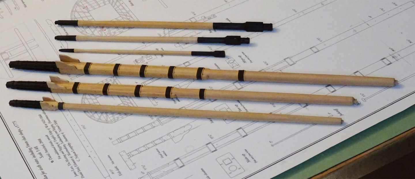
I'm sorry, but it amuses me how difficult folk make things sometimes! I've found the easiest way to make masts and spars is by the simple methods used in the shipyards for centuries using ordinary hand tools. Once you have a square stick of sufficient length, mark out the taper on one face. Plane or use a chisel to cut this on both sides. Re-mark the taper on one of the untapered faces. Repeat. You now have a four-square tapered stick. Mark out for an octagon (use a 7:10:7 proportional scale) along all four faces and note which sections remain square or octagonal. Reserve any square sections. Using a 45 degree spar holder, plane or chisel to cut the octagonal and future round sections. Finally, sand the octagonal sections round using strips of sanding paper. Done. Low tech, low cost in tools. All you need is a good rule, sharp pencil, a sharp small plane or chisel and 45 degree holder.
-
Nice observation of the arrangement of the coamings on Centurion! I wonder if that was usual, as I've never seen this detail elsewhere. Do you know of other examples?
-
Lapwing 1816 Revenue Cutter
druxey replied to iMustBeCrazy's topic in CAD and 3D Modelling/Drafting Plans with Software
There are, generally speaking, three kinds of plans: I) Initial 'class' design lines (often with an annotated list of ships built to those lines and the yards they were to be built at). II) Plans sent out to contracted shipyards with contract specifications, copies as below. III) 'As launched' plans sent back to the Admiralty as a record of the actual construction. Usually launch date is noted on these. If your plans are dated prior to launch, they are most likely copies of Type II retained by the Admiralty. -
Detail sander from an electric toothbrush
druxey replied to grsjax's topic in Modeling tools and Workshop Equipment
I have used an old electric toothbrush with fine polishing powder (pumice) to buff up carvings.- 5 replies
-
- 10
-
-
I have adopted another orphaned kit
druxey replied to mtdoramike's topic in RC Kits & Scratch building
Vastly improved! -
Lapwing 1816 Revenue Cutter
druxey replied to iMustBeCrazy's topic in CAD and 3D Modelling/Drafting Plans with Software
There were several Lapwings, according to David Lyon's The Sailing Navy List. This is an authoritative book. 1) 1764-5 2) 1785-1828 3) 1808-44? 4) 1825-1864 The 1808 ship was, according to Lyon, a coastguard ship built, as you say, in Megavissey, Cornwall. He notes that she was still in service in 1816 (page 333). Possibly built to the same draughts as Fancy of 1817, whose lines and deck plans are extant. (page 334). Perhaps your Lapwing of the 1830's was number 4, above? This vessel was built in Chatham Dockyard. Keel laid July 1823, launched February 20, 1825. She was a packet ship in 1829 and hulked in 1845. This ship was one of the numerous 10-gun brig/brig sloop Cherokee/Cadmus/Rolla class, armed with 2 6=pounder long guns and 8 18-pounder carronades. The packets carried only 3 guns. Nominal crew was 75 men. I hope that the above is of some help. -
You might consider 5 minute epoxy for wood-metal joints.
-
HMCSS Victoria 1855 by BANYAN - 1:72
druxey replied to BANYAN's topic in - Build logs for subjects built 1851 - 1900
And add an electrical heating wire for winter!- 1,021 replies
-
- 2
-
-
- gun dispatch vessel
- victoria
- (and 2 more)
