


druxey
-
Posts
13,128 -
Joined
-
Last visited
Content Type
Profiles
Forums
Gallery
Events
Posts posted by druxey
-
-
-
Excellent method and result, Mike. Well done!
- Canute, Stuntflyer and mtaylor
-
 3
3
-
-
True enough, Ed. But for most builders, they would be more concerned with the external appearance of the framing.
- Canute, Jack12477, billocrates and 1 other
-
4
-
-
-
Ed: The frames are bent in wet, without any heat necessary. They are of such small dimension that this is easily accomplished under slight compression to 'spring' them into place.
- EdT, mtaylor, paulsutcliffe and 3 others
-
6
-
If it's of any assistance, when I've cut frames, generally I cut to the outside line, or no more than 1/64" outside it. Bevelling (except for bollard, hawse timbers and transoms) is left until fairing a complete section of the hull.
If you are going to bevel each frame, would it not make sense to paste the pattern on the 'narrow' side, cut to the 'wide' line, then bevel back to the 'narrow' line of the pattern, rather than try to align patterns on both sides?
- billocrates, Canute, Jack12477 and 1 other
-
4
-
Sounds like a very effective method, Gerald.
-
-
-
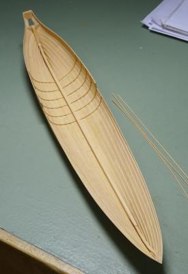
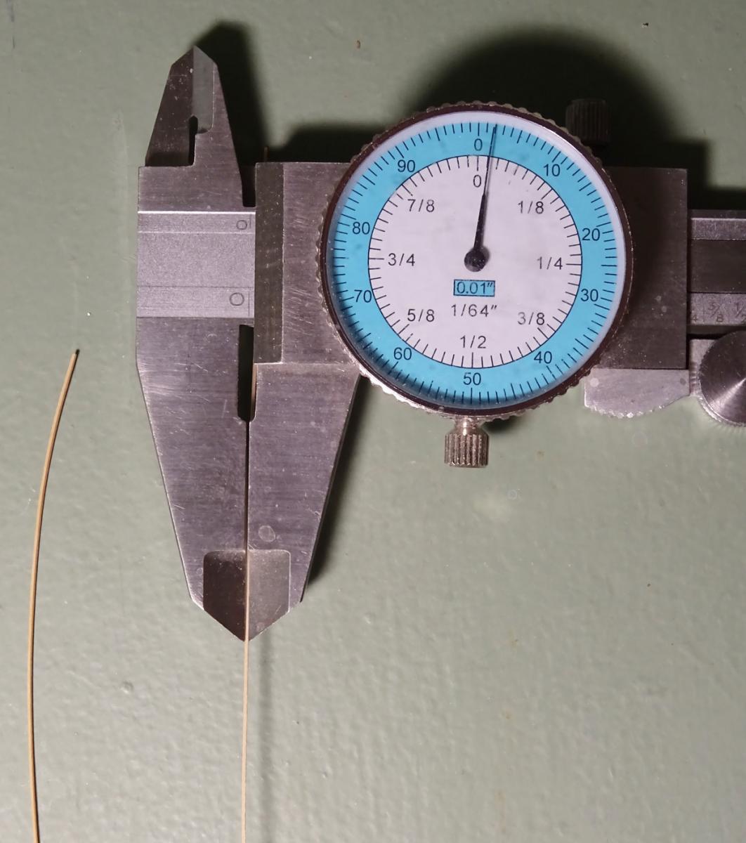
Started bending in the frames today. They are spaced at 18" intervals and, as previously mentioned, are ¾" square. In the real boat, there were floors and futtocks united by a side overlap. However, as this will be completely invisible in the finished boat, I will omit this detail.
As I have other work on hand, the next update will be a few days away.
-
-
For some reason I missed seeing this thread until this morning. Fascinating research and interpretation, Woodrat! You are doing a terrific job in these rather poorly charted waters.
- GLakie, mtaylor, CaptainSteve and 1 other
-
4
-
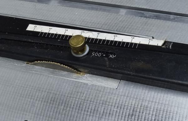
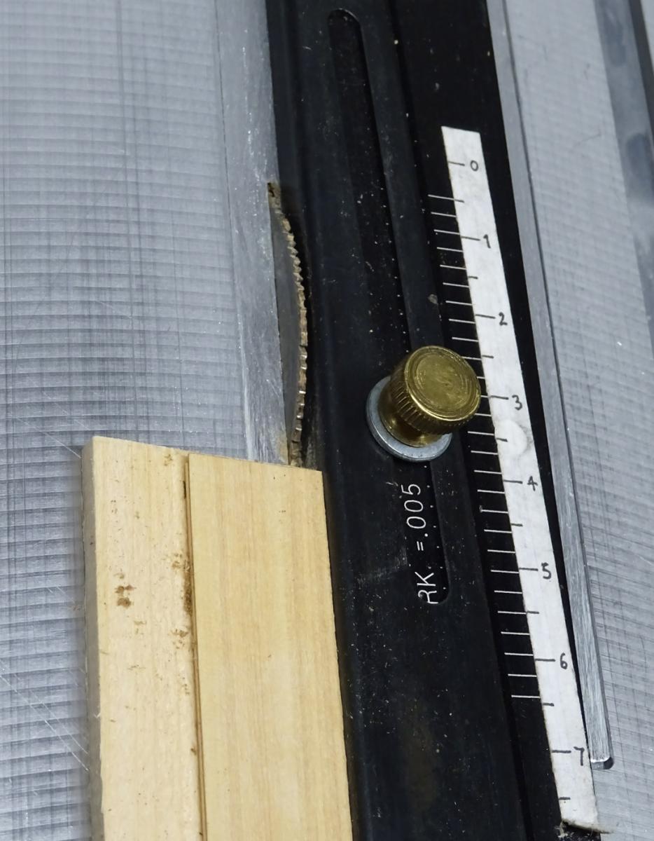
Next is to cut stock a scale ¾" square. This is next to impossible without a zero-clearance table and a slitting saw blade. So I made an insert of aluminum sheet and raised the saw blade through this, as shown (upper left). Note that, on this saw, I have an Accuriser II fence. I attached a secondary scale measuring in inches at 1/48 scale. This avoids having to translate from thousandths of an inch (actual) to scale inches.
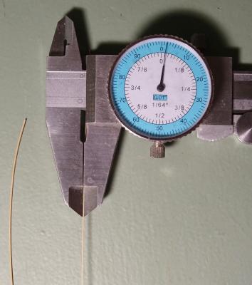
I cut several sheets of 1/64" Castello stock and rubber cemented them to a sacrificial piece of softwood. In this case it was simply a paint stir-stick (upper right). This was then run through the saw and the pieces separated and cleaned up, giving the 1/64" square section required for the frames (below).

- steamschooner, ggrieco, EdT and 28 others
-
31
-
Thanks, Michael. I use white PVA, slightly thinned, applied with a small watercolour brush. The outside is washed down with a damp brush immediately, and the inside is cleaned up afterwards with a dental elevator (looks like a bent mini-chisel). If there is a stubborn bit of glue, a drop of water on a brush does the trick. Should a little of the joint give way, I run more dilute glue into the crack and clamp it shut with one or more of those mini-clips. This rarely happens, as the bevelled land creates a tight joint.
- PeteB, Mirabell61, mtaylor and 15 others
-
18
-
Yes, more or less. There is a photo of this area of Victory that show these T-straps in place. It is shown in Longridge's Anatomy of Nelson's Ships, Plate 19, opposite page 100. I can't post this photo as it may infringe copyright. Hopefully you have access to a copy if you don't already own one. (You should!)
-
-
Thanks again, everyone, for looking in and your comments.
David B: I'm not sure what your question means. Which 'other half' are you referring to?
- Stuntflyer and Canute
-
2
-
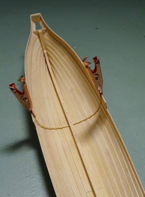
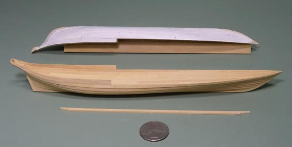
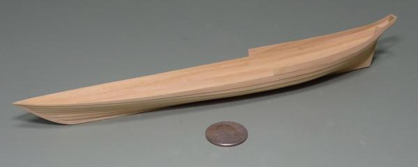
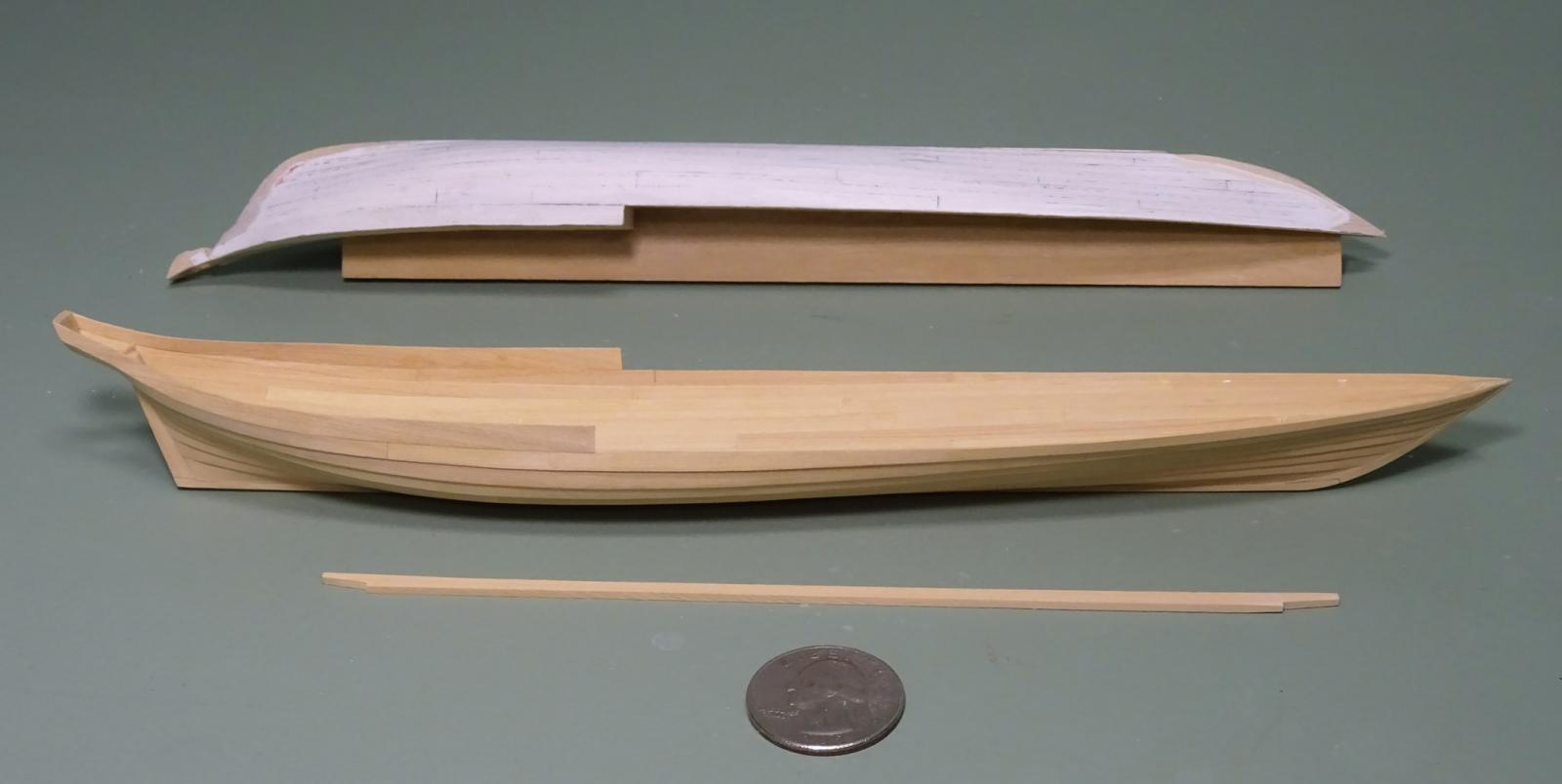
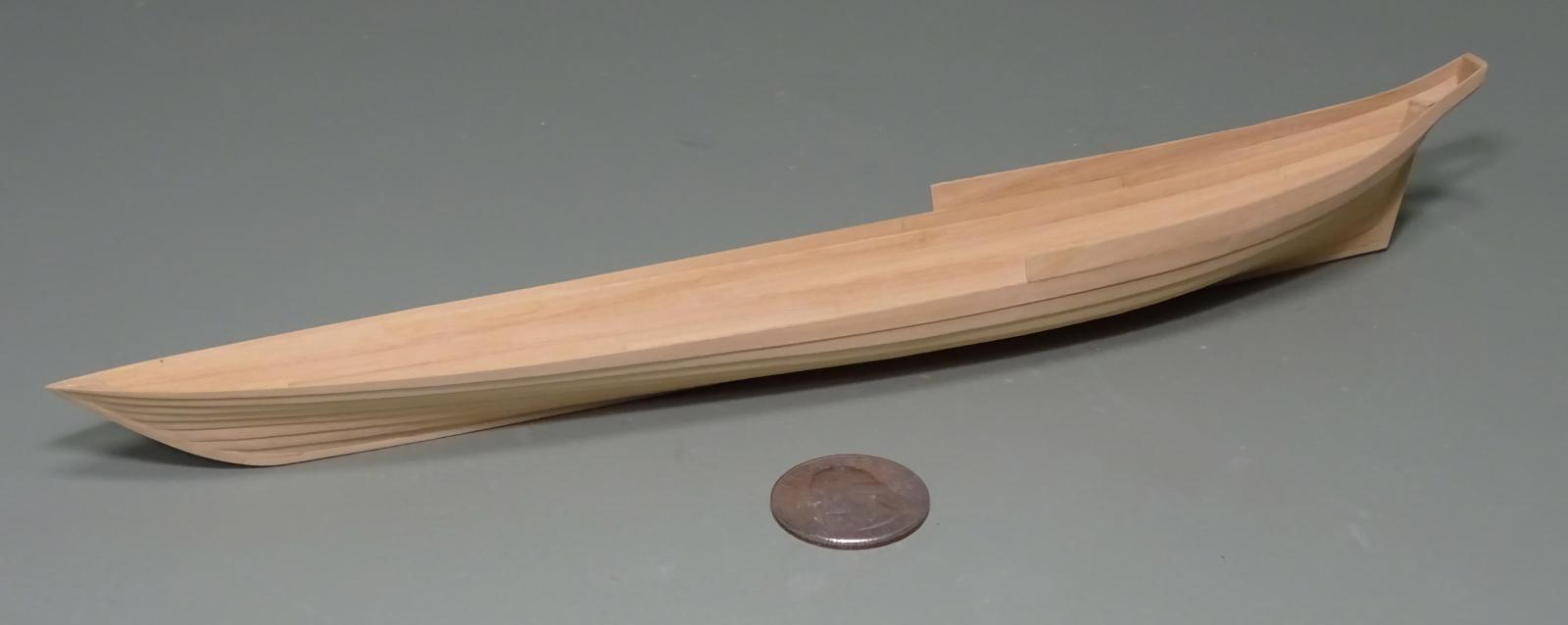
Finally the shell has been completed. It is quite delicate right now, as the last half strake is only edge-glued to the strake below. However, the pink stern is quite strong, even at this stage.
Next will be installing the keelson, followed by bending in the frames. The plug, as you can see, has been beaten up quite a bit in the process of planking.

-
Superbly done, Ed!
- mtaylor, Piet, Calhoun Zabel and 2 others
-
5
-
Thanks again for the likes and comments, everyone. And yes, Ed, I too am mortal!
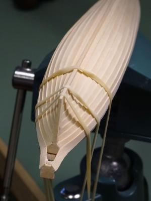
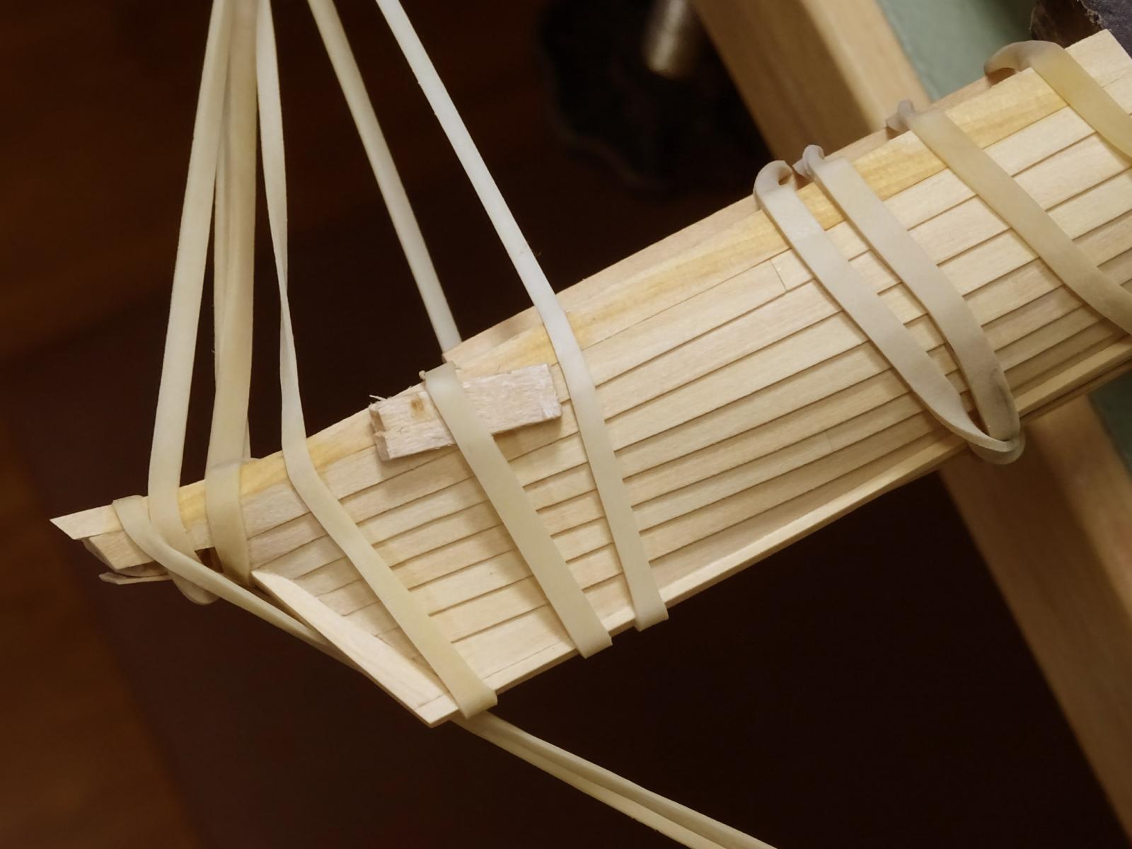
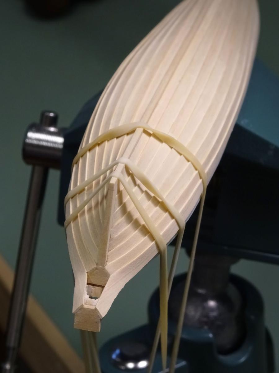
The sequence of construction needs to be carefully considered. Before adding the keelson (making replacement on the plug impossible) a last half-strake needed to be cut and fitted. This will carry all the ornamental scrollwork aft. It has a sinuous S-curve in plan, and required the entire elastic band brigade to damp-shape it into position.

- albert, usedtosail, russ and 30 others
-
33
-
Those T-straps actually ran across the wing transom and up the forward face of the counter timbers. Your photo (post 42) has it placed upside-down. The curve fits on the lower counter area.
- WackoWolf, Canute, paulsutcliffe and 2 others
-
5
-
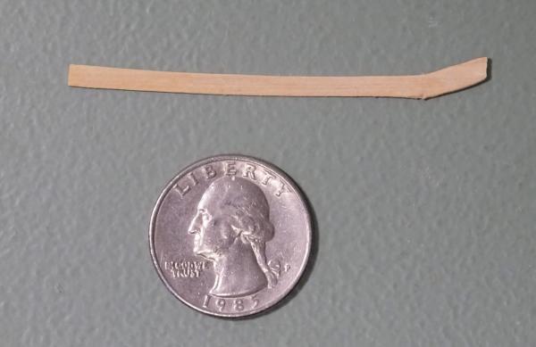
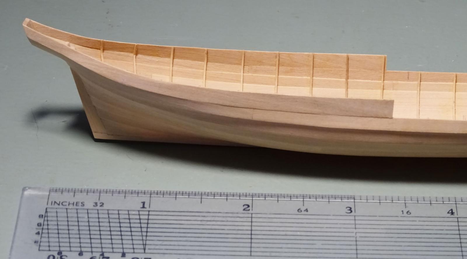
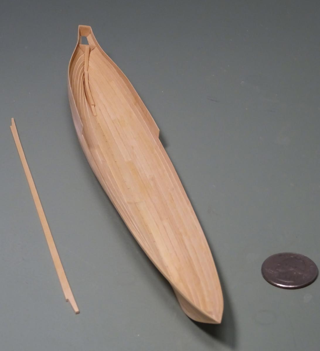
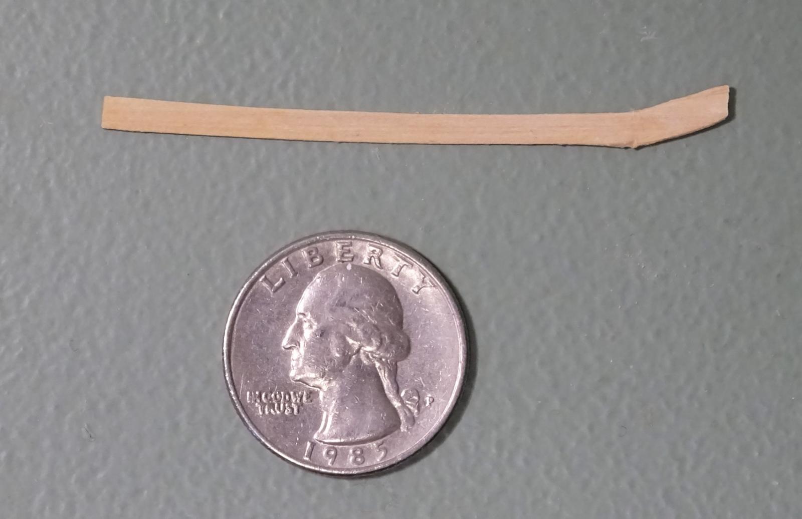
The sheer strake proved challenging in more ways than I had anticipated. First, this strake tapers to a point at the bow. Finessing this was not easy. Secondly, I had a minor mishap. While working with the hull off the plug, my sleeve caught the unsupported aft end of the strake and it snapped off. So, a re-do. I flattened and re-assembled the broken plank to show its peculiar shape. Wes mentioned a U.S. quarter, so I've included one for scale.
I will not remove the shell from the plug again until both sides of the aft ends are complete and united with the outer transom!


Frégate d'18 par Sané , la Cornélie
in CAD and 3D Modelling/Drafting Plans with Software
Posted
John: did you receive my PM from the other day?