


druxey
-
Posts
13,128 -
Joined
-
Last visited
Content Type
Profiles
Forums
Gallery
Events
Posts posted by druxey
-
-
-
Well, you'll all have to wait a bit yet.
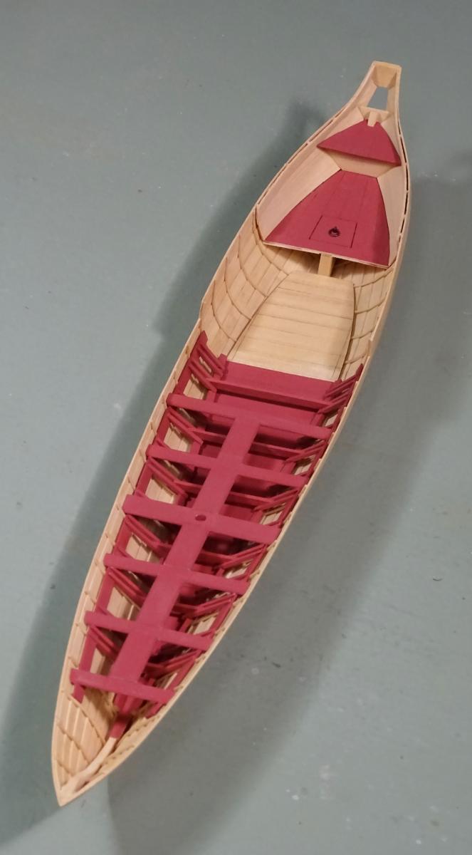
The forward deck/platforms are made and fitted. The same card template strategy was used as for the footwaling and aft platforms. There are a few more details on the thwarts to take care of: iron strap standards that attach them to the side. Then there are small corner benches to make and fit just forward of the coach (cabin).
- ggrieco, tadheus, Cap'n Rat Fink and 44 others
-
 47
47
-
Certainly it isn't a stealer - that term applies to planking. Could be called a sistered toptimber. However, Waldo is more fun, if terminologically inaccurate!
- mtaylor, Canute and paulsutcliffe
-
3
-
Patience, gentlemen, and all will be revealed in time!
-
-
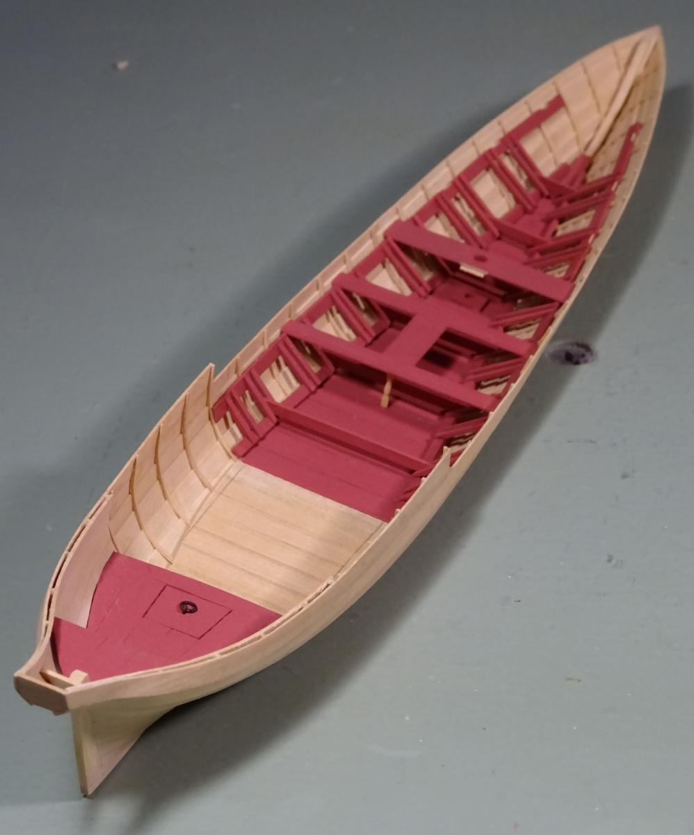
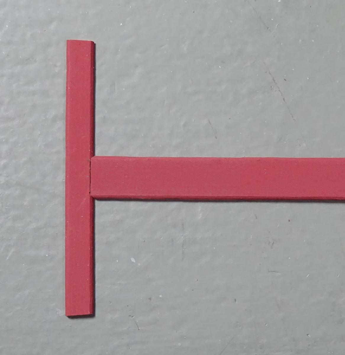
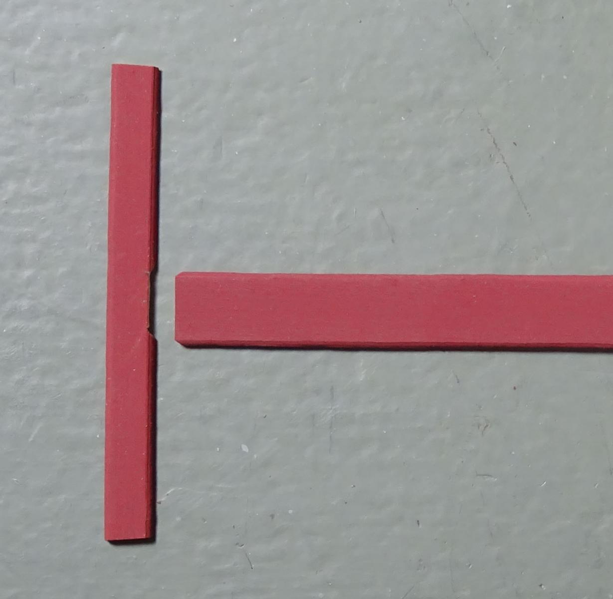
Thanks again for your encouragement, folks.
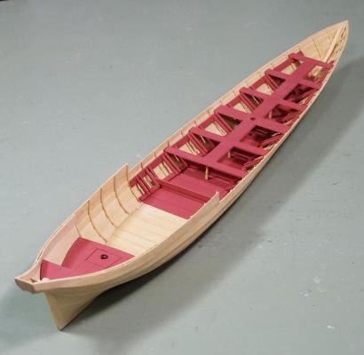
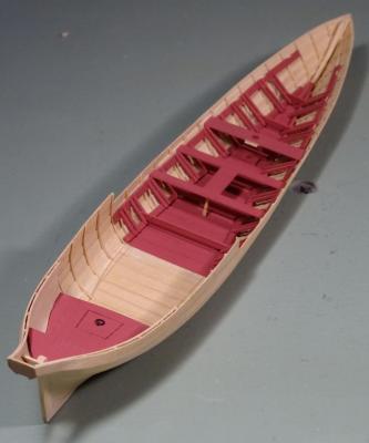
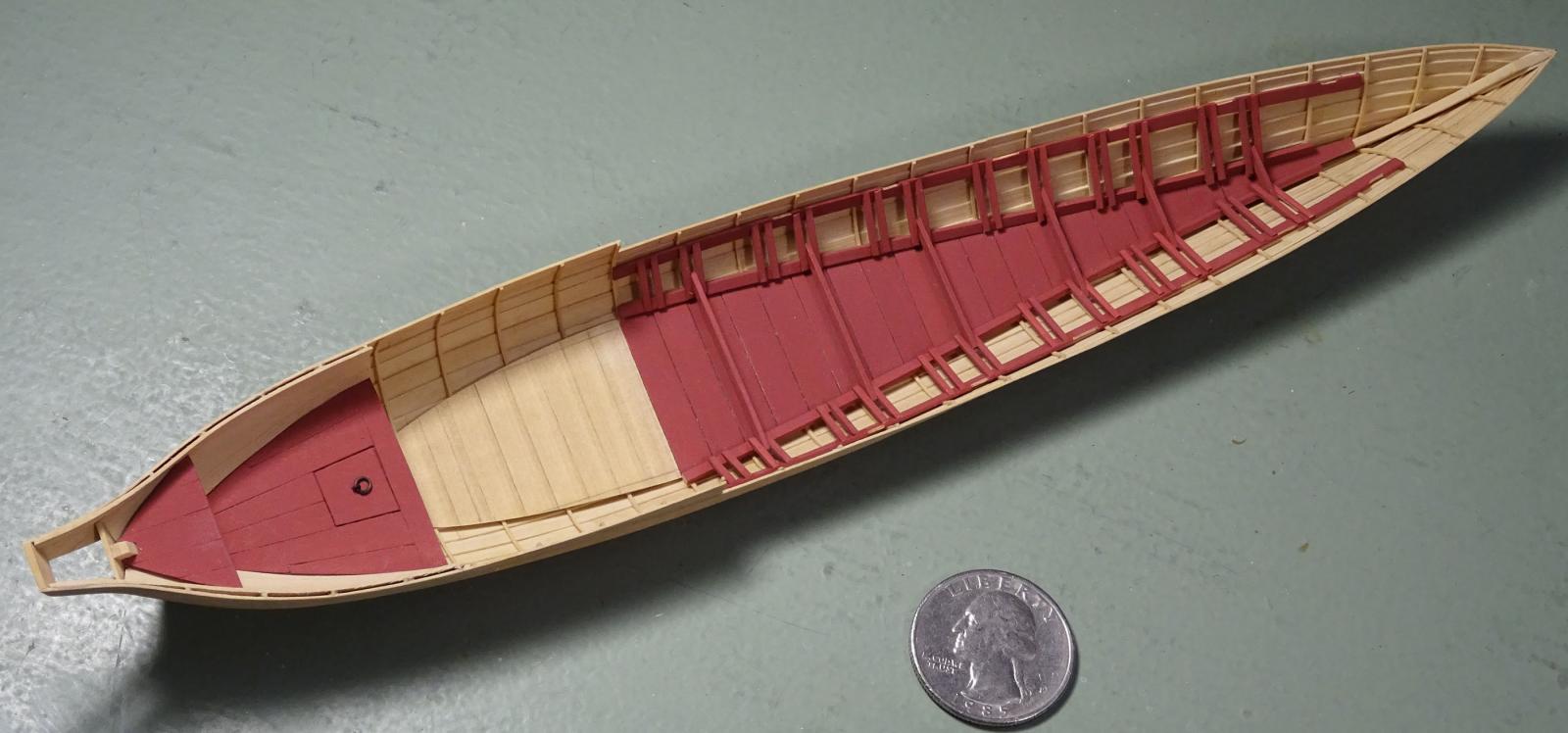
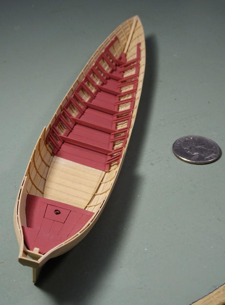
All the thwarts are now in, along with their longitudinal pieces. Once I figured out my strategy, this was easier to accomplish than I thought. After marking out and cutting recesses in the thwart, a small tongue was glued underneath. This prevents the longitudinal strip from falling through and allows it to sit flush to the thwart. The recesses are carefully marked and cut using a scalpel. The longitudinal is cut to length and the corners bevelled to 45 degrees using a fine sanding stick. I found that using a chisel here was difficult, as I could not cut the corners consistently.
Next are the two small platforms or decks forward of the first thwart. That will complete internal work at the fore end of the model.

- captainbob, WackoWolf, Chuck and 32 others
-
35
-
-
-
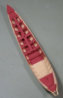
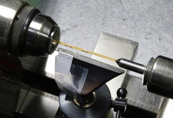
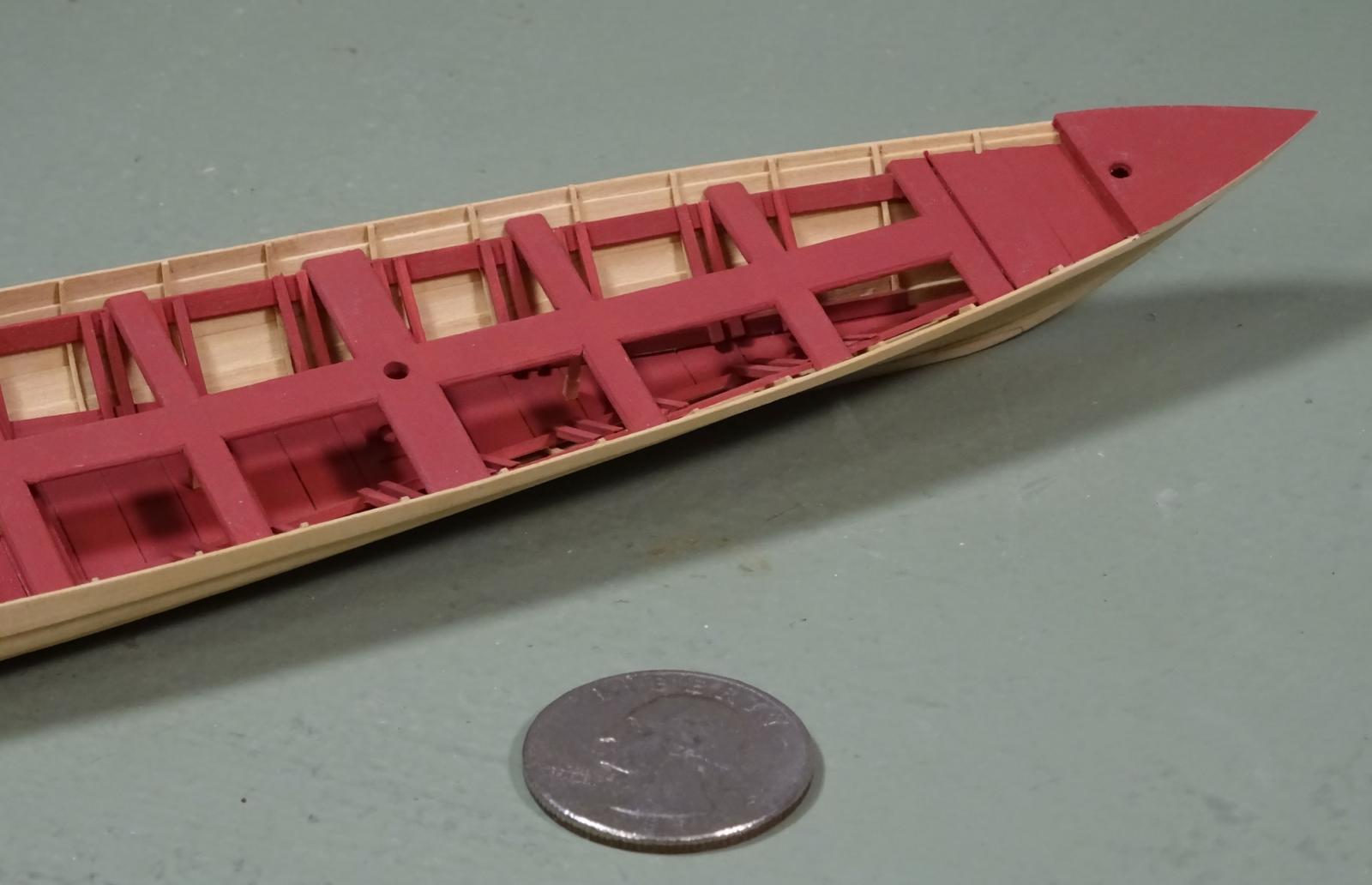
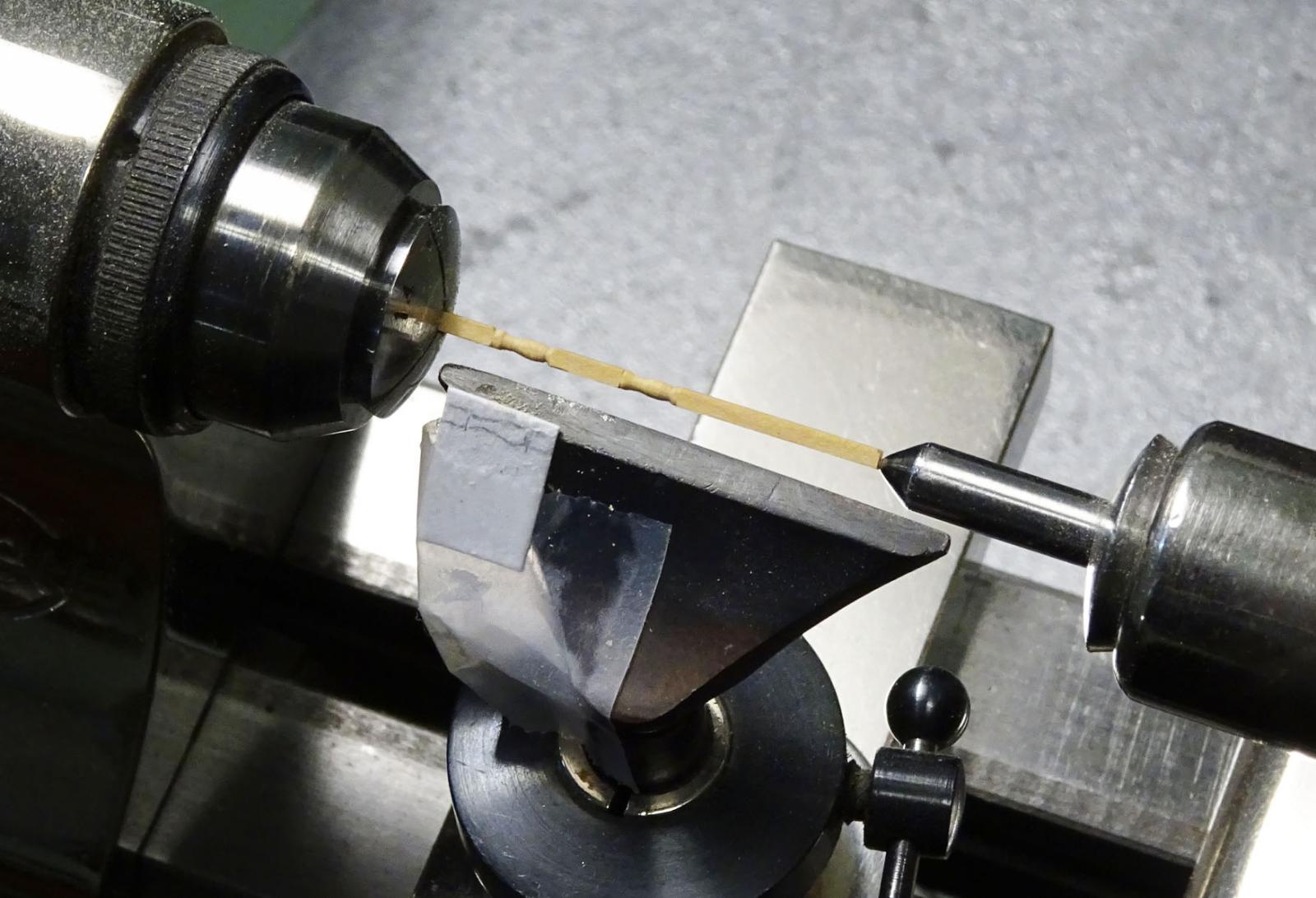
Turned some pillars for under the thwarts freehand with files. As there are only five to make, it was not worth the effort to make a contour pattern. The pillars will be almost invisible in the finished model anyway! The stock was 2" square.
Started cutting and fitting thwarts. The ensign staff step was also added under the wider thwart before the area became inaccessible. The thwart itself has now been drilled for the staff and installed (third photo).
-
-
I don't disagree with your posts, Rob. The 3 bolts per that you indicate in Steel are certainly there! However, what bothers me is the wording, "in each scarph". This implies a further three bolts through each scarph rather than between the floors and futtocks of the frame pairs.
Now, to confuse you further, I looked things up in Steel's Naval Architecture. The three bolts you indicate (square in section, BTW) are specified as having the same dimensions as the keel bolts. BUT, (page 378) Steel mentions treenails, not bolts, through each part of the chocks!
"The frames, when bolted together, have chocks fayed in the seats at the heads and the heels, and fastened with treenails..."
I rest the case, m'lud.
-
Very nice, Mark. Just catching up with your log. I didn't know about 'rudder retrievers'. Must be a new breed?
- Piet, paulsutcliffe, Omega1234 and 5 others
-
8
-
-
-
-
-
-
-
-
-
-
-
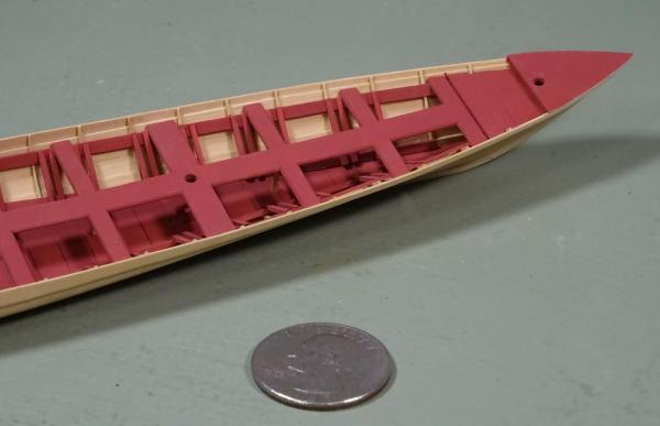
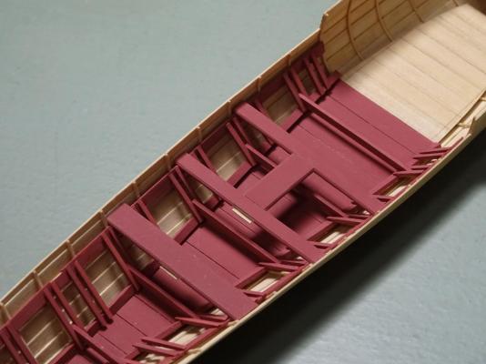
Well, the 48 batten pieces have been cut, shaped and installed, along with the six footboards.
Next will be the thwarts. They should be a simple job, but are complicated by the fact that the edges are moulded and need to be mitred to the longitudinal strip running down the mid-line of the boat. Also, six turned supporting pillars are needed to support the thwarts. Stay tuned.


-


Greenwich Hospital barge of 1832 by druxey - FINISHED - 1:48 scale
in - Build logs for subjects built 1801 - 1850
Posted
Guy: it's an optical illusion, I think.
Thanks again, everyone, for dropping in. There may not be another update for a week or two, as other more pressing work has to be completed first. Please check in again toward month's end.