Dziadeczek
-
Posts
645 -
Joined
-
Last visited
Content Type
Profiles
Forums
Gallery
Events
Everything posted by Dziadeczek
-
 Ronald, Check it out, what Gebhard Kammerlander does with wet wood strips and a hot soldering iron. The video is rather old and not the best quality, and in German, but you can see what is possible with this technique and what is not. You do not have to use his electric plank bender, just a regular soldering iron should suffice (with a heat control, if possible, not to burn the wood). Besides, the degree of wood bending also depends on wood species your planks are made of. Some wood is quite brittle, some very stiff and springly and some very pliable (pear, and somewhat stiffer cherry). The thinner the plank is, the more you can bend it, all the way up to 360 degrees! Pre wet your planks in luke warm water for 5 - 10 minutes and, while they are wet, heat bend them to a desired curve. Sometimes you have to do it in stages, wetting them and bending, and so on. If you overbend your wood, you can unbend it - using the same technique. Your planks look rather brittle, I don't know the wood specie (perhaps mahogany?), but you might try to replace them with some fruitwood and heat bend them, instead of using the planks supplied in the kit. Good luck! Thomas
 -
Why did you enclose plans for the USS Constitution? This link Ship Model Laboratory - Centre for Maritime Archaeology and Conservation - Texas A&M University (tamu.edu) explain the whole process well, and even though it doesn't apply to the Wappen von Hamburg, but the principle is the same.
-
Aren't you going to cover these "holes" with a waterway strip?
-
This painting reminds me of another one - a large mural in the Air Museum in Palm Springs, California... Different ships, different planes though, but... Thanks! 🙂

-
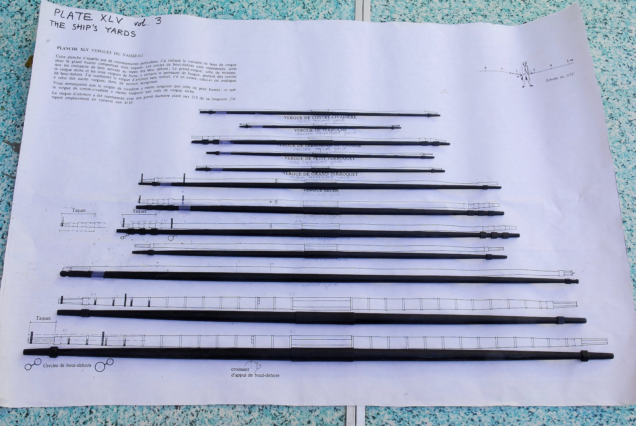
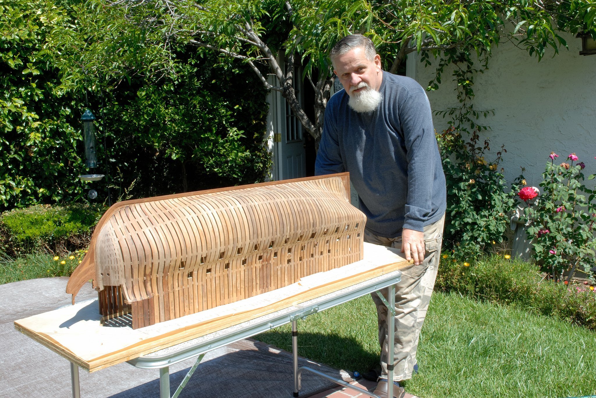
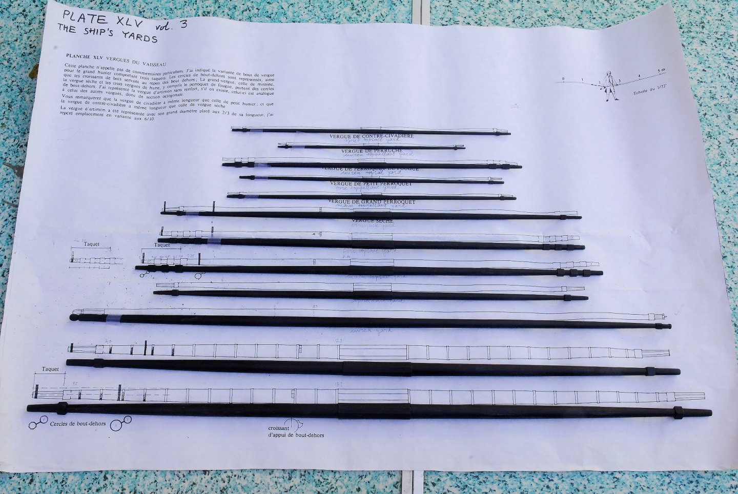
I recently turned all yards for my "Frenchie" on my Sherline lathe (long bed type). With the exception of a few shortest ones, all others were too long to do it from one square piece of wood. So I had to do them in sections (three), two 'arms' and one center octagonal piece. Afterwards I glued them together with round pegs (flutted dowels) and Titebond glue into predrilled holes. The joints are invisible.
-
"The Home Machinist's Handbook" by Doug Briney and "Tabletop Machining" by Joe Martin Both are talking mostly about the Sherline, but general principles are the same for all.
-
With a metal lathe you can turn soft metals (brass, copper, aluminum and perhaps even soft steel) as well as wood, but with a wood lathe you can only turn wood. Good quality lathe (Sherline, Proxxon, Taig) doesn't come cheaply, though... On the other hand, it is an investment for life...
-
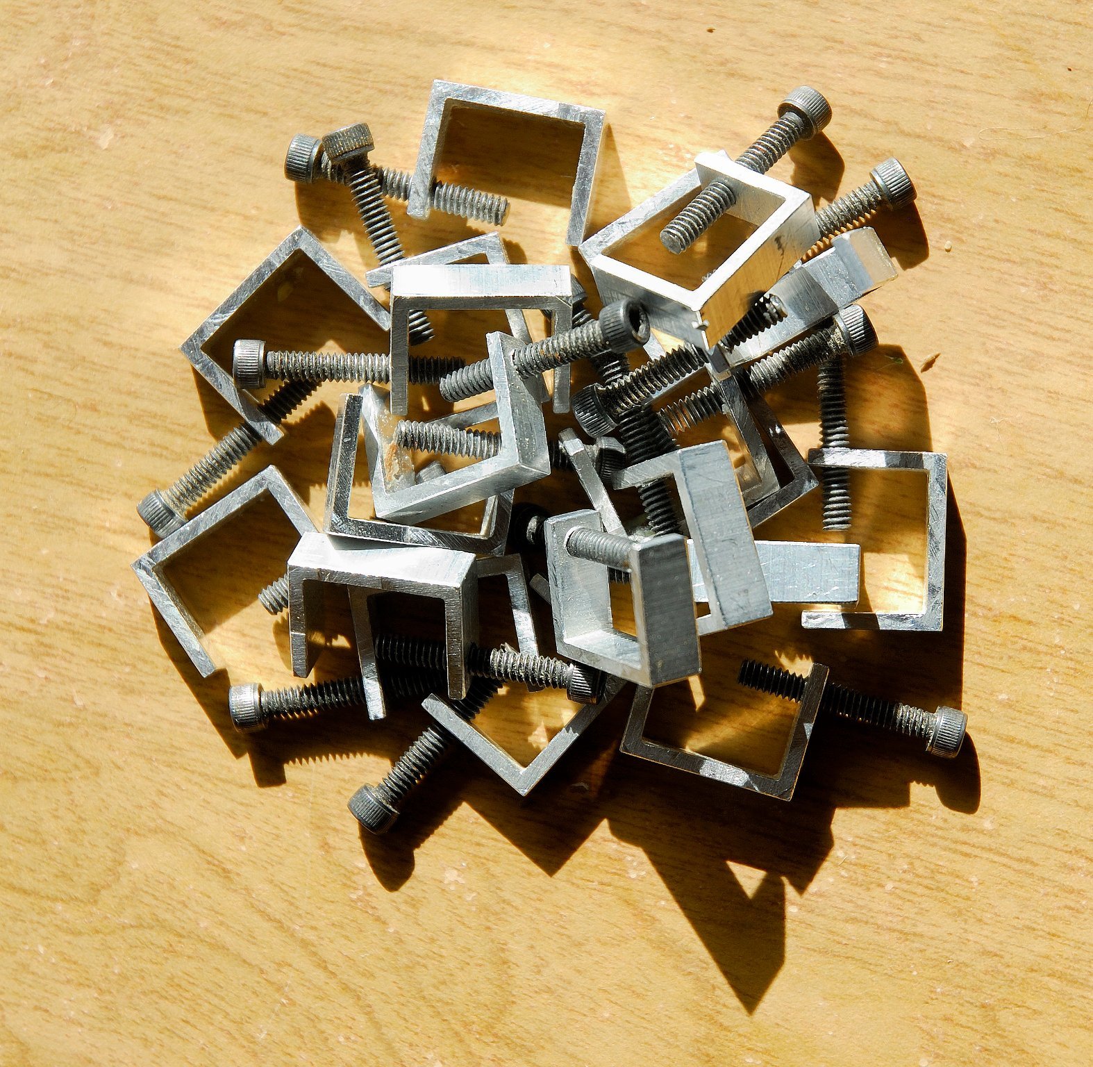
I once made a handful of such mini C clamps from a length of aluminium U channel, slicing it on my Preac saw into narrow sections, drilling holes and thread tapping them to match my screws. Mine have 1/2 inch throat size, but perhaps you could also find your size in a hardware store. These are not heavy duty, plenty of power to hold planks, though.

-
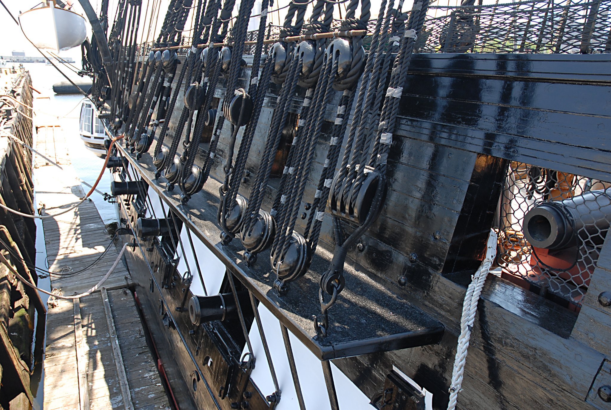
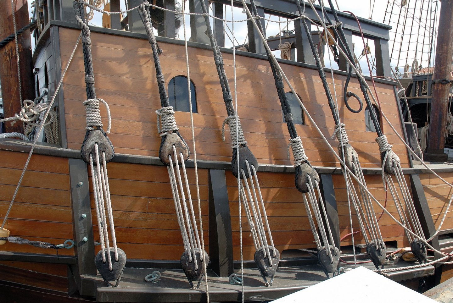
This is how it is shown on the newly (then) constructed replica of the San Salvador galleon in San Diego. Right or wrong, I don't know? And here is the USS Constitution in Charlestown

-
I have done some search on the silk span for sails. On this forum and elsewhere. Also bought a brochure by D. Antscherl. I am thinking about using this material for my sails. What grade (thickness) should I use? Light, medium or heavy? The scale of my model is 1:48.
-
Proxxon compound table KT 70
Dziadeczek replied to Dziadeczek's topic in Modeling tools and Workshop Equipment
Thank you all for your input. I decided to follow your advice and get a PM40 vise for my table. I'll let you know, if it fits. Thanks again, 😀 Thomas -
Hi, Sometime ago I bought their compound X/Y table KT70 and now I am pondering whether I can mount on it their Proxxon machine vise MS4, and avoid these ungainly clamp jaws ? I am unable to determine this based on my search, if the two are even compatible? Neither the net, nor the original instructions clearly state this. Did anyone managed to do it? How? Thanks in advance! Thomas
-
DMC Cotton
Dziadeczek replied to Wacom's topic in Rope Making/Ropewalks's Discussions about Rope Making
Anchor is just as good as DMC, if not better. -
Harold Hahn method
Dziadeczek replied to Essayons's topic in Building, Framing, Planking and plating a ships hull and deck
THANKS. 😀 Yes, I did it. (The pic I attached is now, sort of, old...) The more current state of affairs is here (entry # 60) + recently I attached all 5 anchors as well. -
Harold Hahn method
Dziadeczek replied to Essayons's topic in Building, Framing, Planking and plating a ships hull and deck
I know, I bought that brochure from Ancre. But, it was only AFTER I drew the remaining frames by myself, so, for me it was like a proverbial "mustard after dinner". You are right, my model is in 1:48 scale. I intend to build it fully masted and rigged, with sails, if my endurance will permit. Whether it is built strictly in Admiralty style or not, is of less importance to me. I used this name remembering all those models with unplanked lower hulls and partially planked decks. OK, perhaps the better name is - a Navy Board ship model! It is some kind of hybrid, I think. What I wanted to show here is the way I built it - in the H. Hahn's method, upside down, mounted in a flat base board, with those extensions of frames (later on to be cut off). Yes, that way is a lot more wasteful of wood than shaping individual futtocks and faying them together and assembling the hull right-side up. But, at that time I was less experienced and fell that the Hahn's method was better suited for me. I also used American walnut for frames (which I wouldn't do today). Some fruitwood would be better... Overall, my model represents largely my own artistic license and not necessarily some rigid convention, Admiralty or Navy Board, or such... The principal reason for my build was to learn all those intricacies of historic ship building practices - in this case French ones. Just reading Boudriot's books was very educational, but later on building a model after them, was an entirely different quality... 😄 Best regards, Thomas -
Harold Hahn method
Dziadeczek replied to Essayons's topic in Building, Framing, Planking and plating a ships hull and deck
Years ago I built my French 74 gun ship upside down, mounted in H. Hahn's building base, following his method (sort of). I remember, I had to add (draw) the remaining frames, since J. Boudriot only has shown in his books the so called, station frames. The hull turned out OK, not perfect though, but - for the first scratch built, Admiralty type model, - acceptable. Right now I am starting to install the running rigging on it. Thomas
- 68 replies
-
- 15
-

-

-
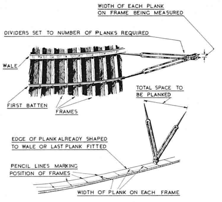
Some degree of edge (lateral) bending is possible, if you pre-wet your plank in luke warm water and carefully heat bend it. Long time ago I posted an entry on this topic, including a link to a short video by a German modeler Gebhard Kammerlander who demonstrates this technique. He speaks German, but the video is "in English" for everyone to understand 😁 . Go about 3/4 down this page to find the video. I learnt how to spill planks from an excellent brochure by the late Jim Roberts "Planking the built up Ship Models", (which, I understand, is still available from Model Expo). Jim describes there authentic practices of ancient shipwrights (a bit simplified for ship modelers). This technique never failed me. I use a set of proportional dividers (a paper strip alternatively), and I fashion two planks at the same time - one for each bulwark (since they should be identical, if your hull is perfectly symmetrical). I sand one edge of a plank a bit angled so that it abuts tightly the next plank on a curved hull. Regards, Thomas
-
Focus Stacking
Dziadeczek replied to Dennis P Finegan's topic in Photographing your work. How to do this.
This was my very first attempt at focus stacking, using my old Nikon d200, standard kit zoom lens 18-70, a tripod, no rails. Merging on Photoshop. I am quite satisfied with the result. What do you think, guys? Thomas
-
I wouldn't worry too much about the filling pieces now. Make all hawse frames first and make sure they all fit and that their external surfaces are smooth (inner surfaces will later be smoothed). And only then try to make those fillers, carefully sanding down their thicknesses to fit to the available spaces in between the hawse frames. I too had a hard time making them for my "Frenchie" (of course, later on I bought the addendum brochure from Ancre with all profiles of the missing frames, including the hawse timbers, but it was already after I managed to shape them all by myself from the waterlines). Tough luck...
-
Planking Question
Dziadeczek replied to Malazan's topic in Building, Framing, Planking and plating a ships hull and deck
Also you can plank your hull with full length planks and afterwards score each plank across with a sharp exacto blade to imitate the joints between individual planks. I think this way might be a bit easier rather than trying to shape each shorter plank individually and identically to the rest of the short ones. -
Could I please. trouble you for a close up photo of your figurehead? What is it made of? Regards, Thomas
-
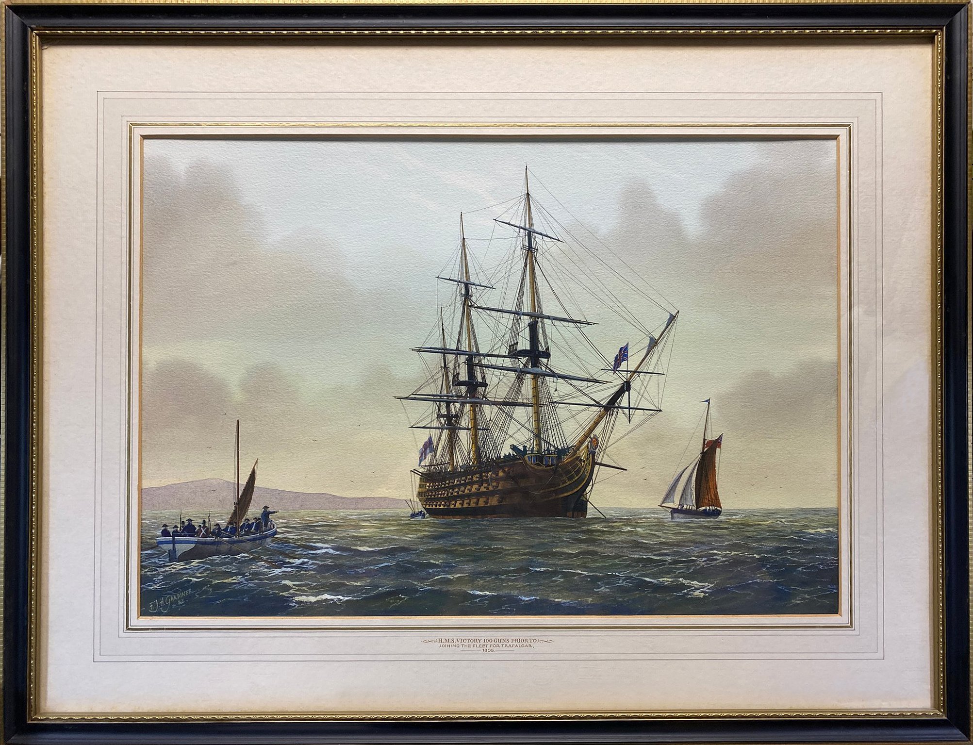
I think it might be a gouache (a little thicker, less watery watercolor, applied a bit more opaque). To make sure however, it is not a print, you might remove it (carefully!) from the frame and see if the paper has a slight indentation along the edges - if it does, that means that this indentation was caused by a graphic's press, and the artwork is/might be a print, like a lithography. But, in such instance, the artist would routinely write in pencil at the bottom margin the number of this particular issue, and the total number of the issues intended, as well as his/her name and the title of the artwork. Here we don't have any of this, at least I cannot see it. So, probably it is a painting (very well executed!), either a watercolor, or more probably a gouache.

-
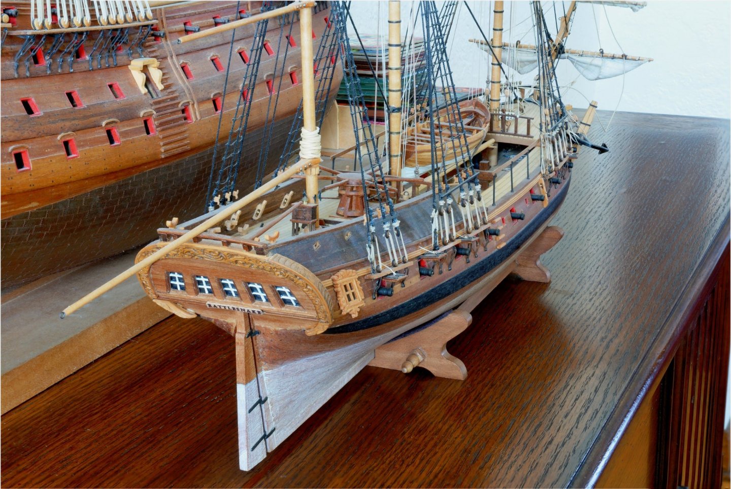
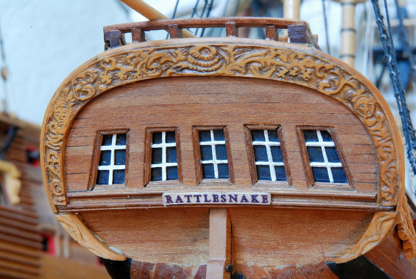
Hi Javajohn , Since I built this model a long time ago, I don't remember now how long it took me to carve the transom. A few hours, at most. (I am a painfully slow modeler, I once knew a Japanese modeler, who would build three very intricate models in the time it took me to build one!) Today I took a close up, macro pic of this transom. When I look at this pic, I think that it was rather a thin slice of boxwood I carved, instead of cherry - the color is more creamy/yellowish. The rest of the stern is cherry though. I remember I made for this task a few tiny carving gouges, two from old discarded Dremel tips ground to the desired shape, and two or three from medical needles with their tips ground properly. You cannot buy such small gouges for this work anywhere, as far as I know! Alltogether, this model is quite difficult and tricky to build, due to its small size. I remember they said that it was intended for an intermediate modeler, but I think that because of the size of tiny details and their delicate nature, it should be build by a more advanced modeler. One has to have a delicate touch and respect for the wood, plus very sharp tools... PS: I just first noticed this glue blob oozing from the underneath of the lower left end of the transom; the pic is much larger than the model, so it exaggerates details and imperfections... Happy modeling!
-
A few pictures from the Vasa museum of ship models
Dziadeczek replied to Torbogdan's topic in Nautical/Naval History
Here are some more pics of this magnificent model. 😃 Photos of Vasa 1 : 10 scale model in the Vasa museum Stockholm (modelships.de)- 1 reply
-
- 5
-
-
I carved my own transom from a thin piece of wood (cherry, if I remember).