


Stuntflyer
-
Posts
1,196 -
Joined
-
Last visited
Content Type
Profiles
Forums
Gallery
Events
Posts posted by Stuntflyer
-
-
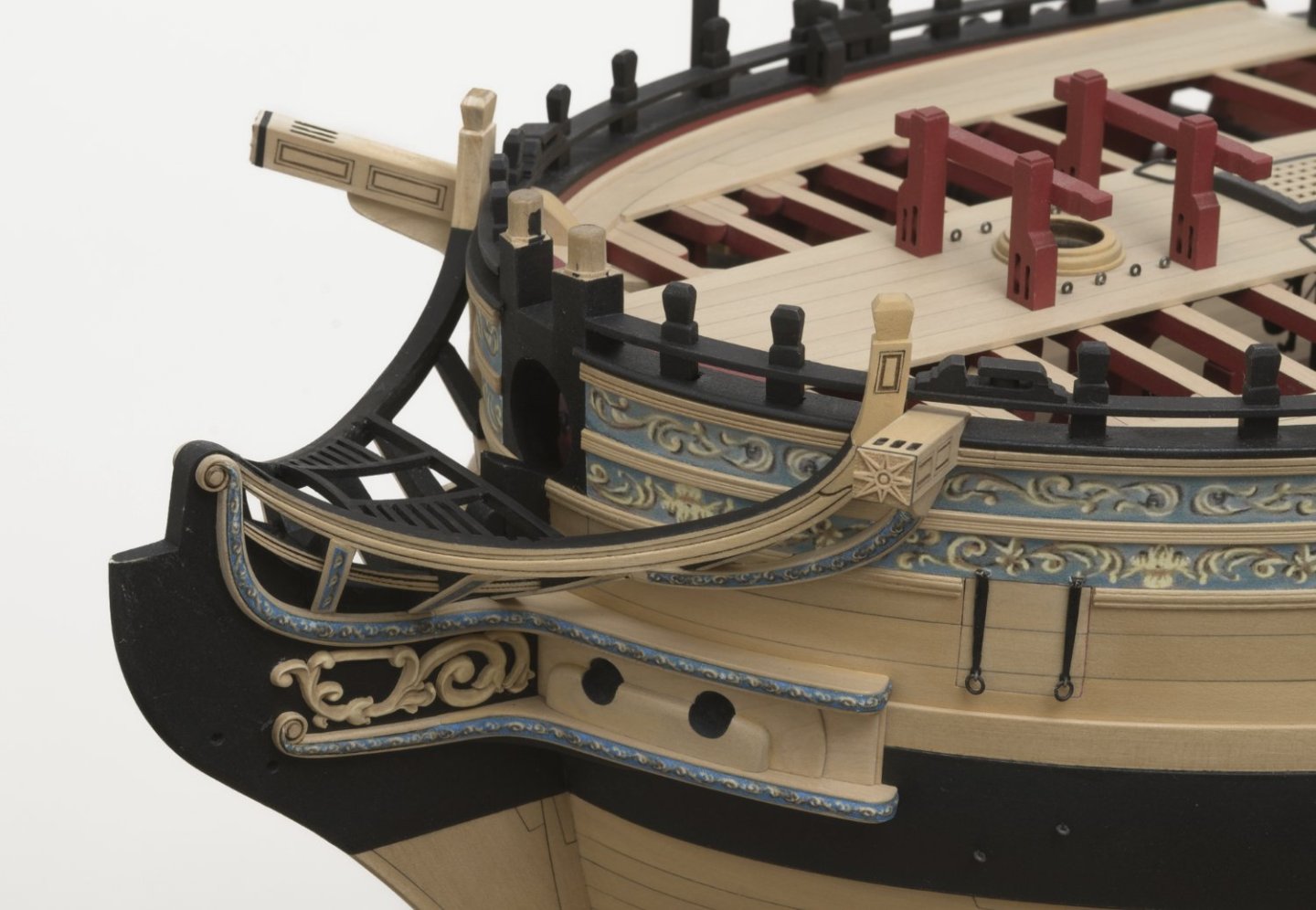
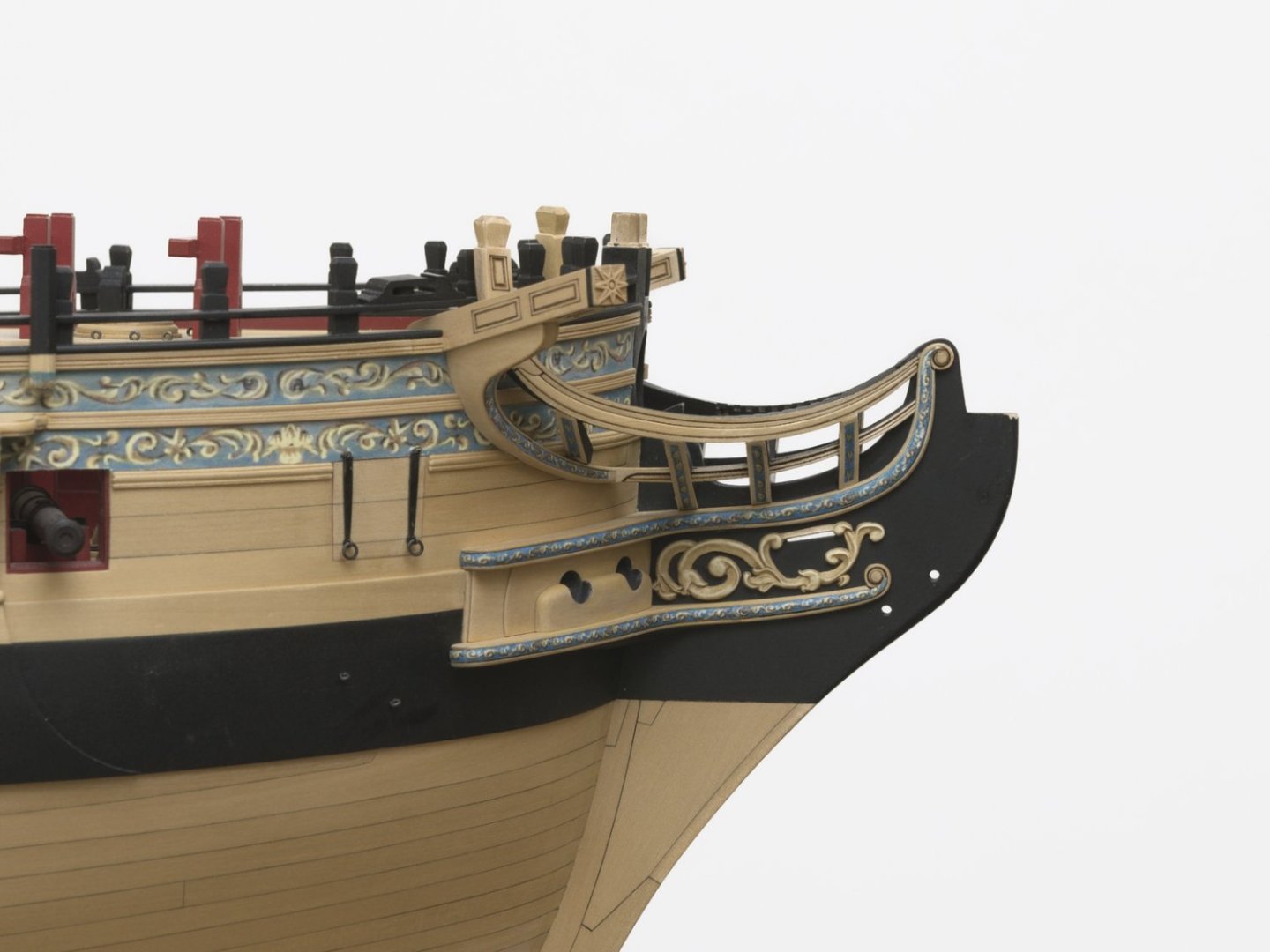
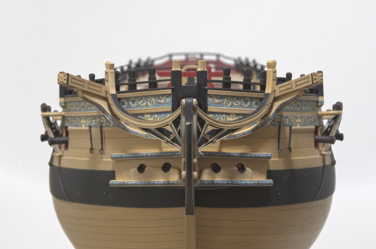
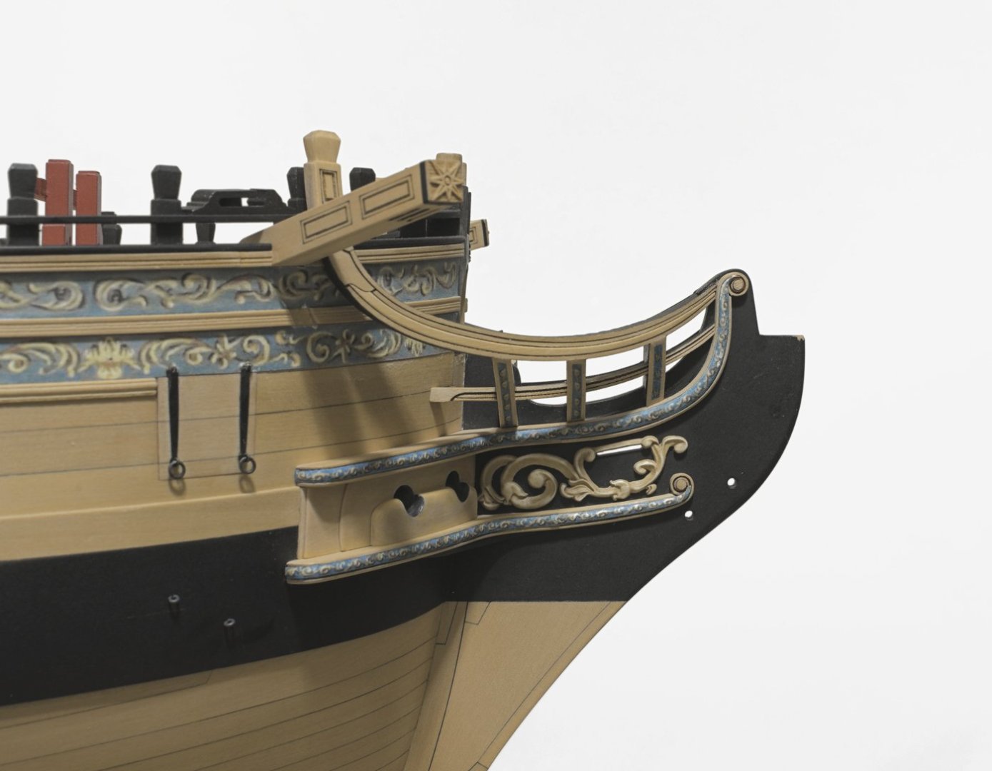
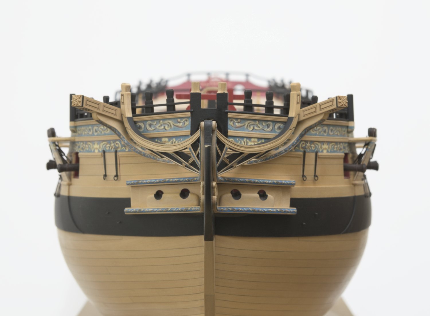
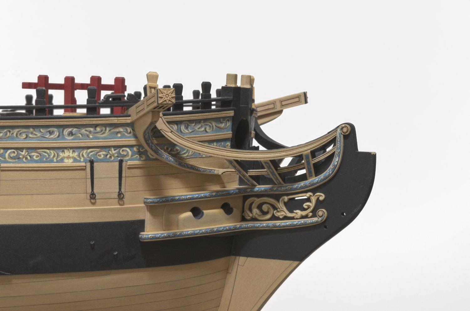
More grating work completed this week. As you can see I have not spent a lot of time on paint work. It's just too easy for things to get scratched while working in this area. I lowered the notched batten at the hull around 3/64" since the angle appeared just a bit too steep.

Mike
-
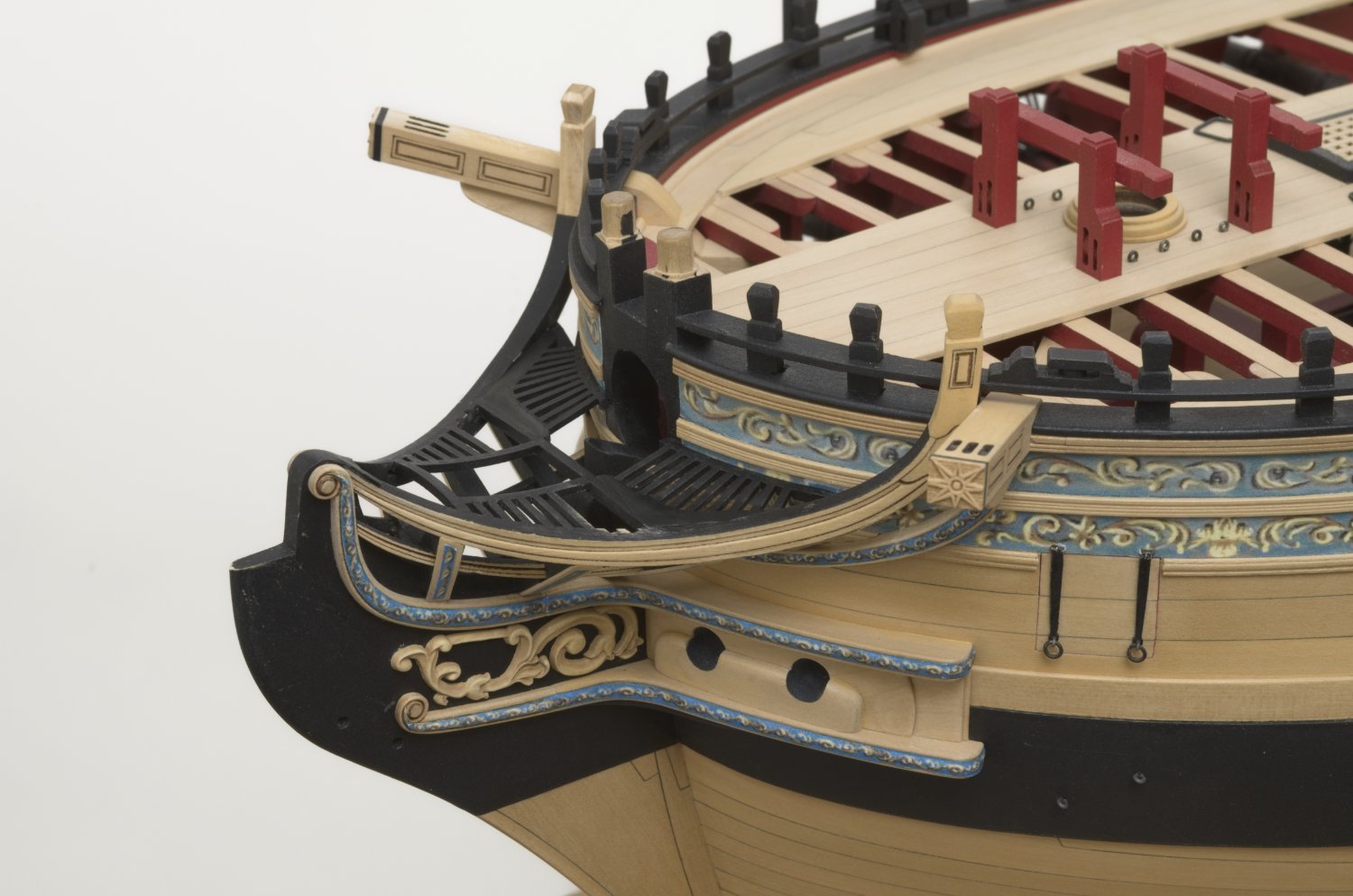
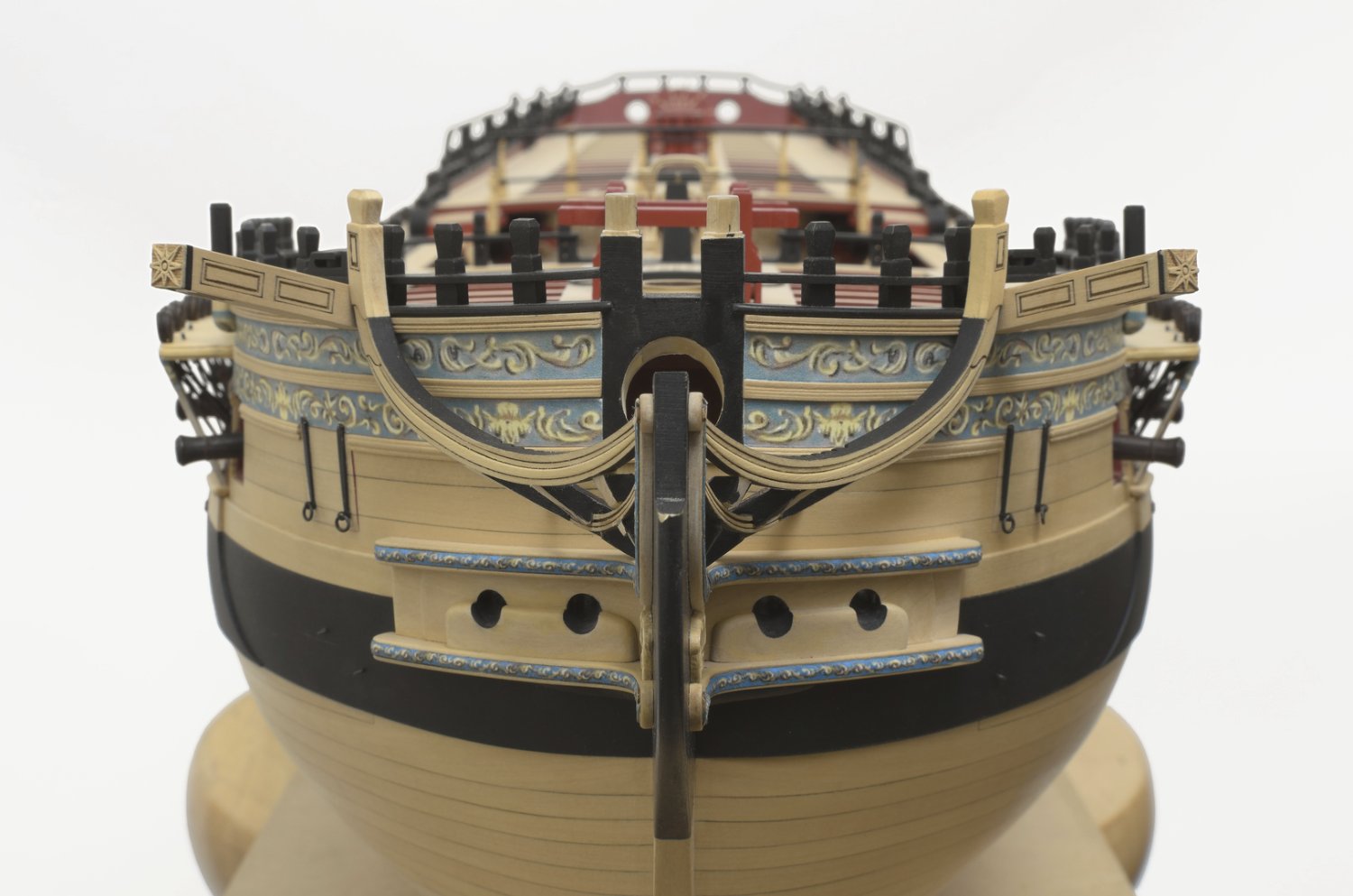
I've started on the head gratings. A few of these battens are quite small, yet none of them managed to fly off into nowhere land. All of the joints needed a bit of wood filler before painting. I added the first coat of black paint of which more are sure to come.
Mike
-
On 10/4/2022 at 8:55 PM, Chuck said:
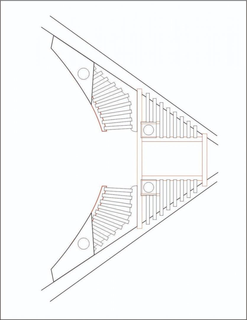
You want that first notch to line up directly across from the one on the knee so those first two battens are straight with the center line.
Chuck,
Regarding the head gratings, specifically the two inner battens that run from the knees to the hull. The drawing shows them skewed slightly. Should I ignore that and stay parallel to the center line of the hull?
Mike
-
Moving right along. .Did you have fun making the port lids? They look quite nice.
-
-
Well, I'm not sure if I would call it a milestone, but it does feel good to have finally finished the head timber work. It's challenging and sometimes tedious work. The secret to any kind of success is to just slow down and think things through as much as possible. The head gratings are next.

Mike
-
You're ship is looking really nice!
-
Looking very nice! You'll see her really start to come together when you do chapter 11.
- FrankWouts, Rustyj and JpR62
-
 3
3
-
Thank you all for the kind words and for all the like's!
Chuck, I still have to complete the two aft head timbers. I did remove the lower moulding which should make things easier. It's a tight area to work in. Stay tuned. .
- FrankWouts, scrubbyj427 and JpR62
-
3
-
Work continues with the completion of the cathead rail. A ton of fitting, tweaking and re-fitting in order to get something that I liked. It would be great if one could add the thin outside layers in one piece instead of a splice. Of course that would be more difficult to do since both halves of the rail would have to be glued together first, while matching the shape of the hull at the same time.
Anyway, here you go. .

Mike
- FrankWouts, CiscoH, TomShipModel and 20 others
-
19
-
 4
4
-
Check the run of the strips with the ship upright. You don't want it to look like the strips are sloping downwards. A gentle slope upwards as they run into the stem is preferred.
Mike
- Ryland Craze, FrankWouts and CiscoH
-
3
-
-
I've been looking forward to getting the cover boards completed, not necessarily doing them. I had to file down a few of the head timbers or change the angle slightly before I could glue the boards in. I recommend using slow drying CA and not PVA. I also removed some of the moulding under the frieze to make things easier when it's time to fit the lower rail.
Anyway, now that they are done I am feeling pretty good about how they turned out. Now its onto the lower rail.
Mike
-
-
Well Greg, you have built a beautiful ship and seven years of your work certainly has paid off in spades. Even at 1/4 inch scale, Speedwell is a small ship and you have shown all of us what a master builder can do.
Mike
- Keith Black, druxey, billocrates and 3 others
-
5
-
 1
1
-
-
They are not that difficult to make. . Wet the wood and bend them together or separately while clamped around a curved shape similar to that of the hull. A large can or plastic container works fine. I sometimes use a round table edge like the scroll saw table. The bend always allows for some spring back. Hot heat dry with a hair dryer for a few minutes, and then let everything cool completely. I always make these pieces longer than needed to allow for clamping. Once the spring back is reduced substantially it should be easy enough to shape and clamp them to the hull.
Anyway, that's how I made mine on the Winnie.
Mike
- tlevine, shipmodel, Seventynet and 2 others
-
5
-
-
I buy these from https://www.harveytool.com/
These are end mills for plastics. They are not cheap, but seem to work quite well on boxwood. They are long reach too. The end mill I mentioned is # 938931. https://www.harveytool.com/products/tool-details-938931
They will send you their catalog. I usually call them and they direct me to a local distributor to place the order. Harvey tool: 800 645 5609
Mike
-
-
-
1 hour ago, Chuck said:
This is as boring and repetitive as making cannon carriages.
Repetitive, yes. Having made all of the frames scratch on Hayling, I never found it boring. I’d rather do that than carriages any day. But, that’s just me.
looking really nice!
Mike
- Ryland Craze, Rustyj, druxey and 2 others
-
5
-
-


HMS Winchelsea 1764 by Stuntflyer (Mike) - FINISHED - 1/4" scale
in Member Build logs for the HMS Winchelsea
Posted
One thing I almost forgot to mention. .
I think that It's very important to keep the two inner battens parallel or at least at the same angle relative to the center line of the hull. It's quite noticeable if one batten is at a different angle than the other. Just something to be aware of when you get to this stage of the build.
Mike