Beef Wellington
-
Posts
2,249 -
Joined
-
Last visited
Content Type
Profiles
Forums
Gallery
Events
Everything posted by Beef Wellington
-
 Love the way your Endeavour is coming together Dave, very nice indeed. The walnut doesn't seem to have tripped you up at all with split/flaky edges.
 -
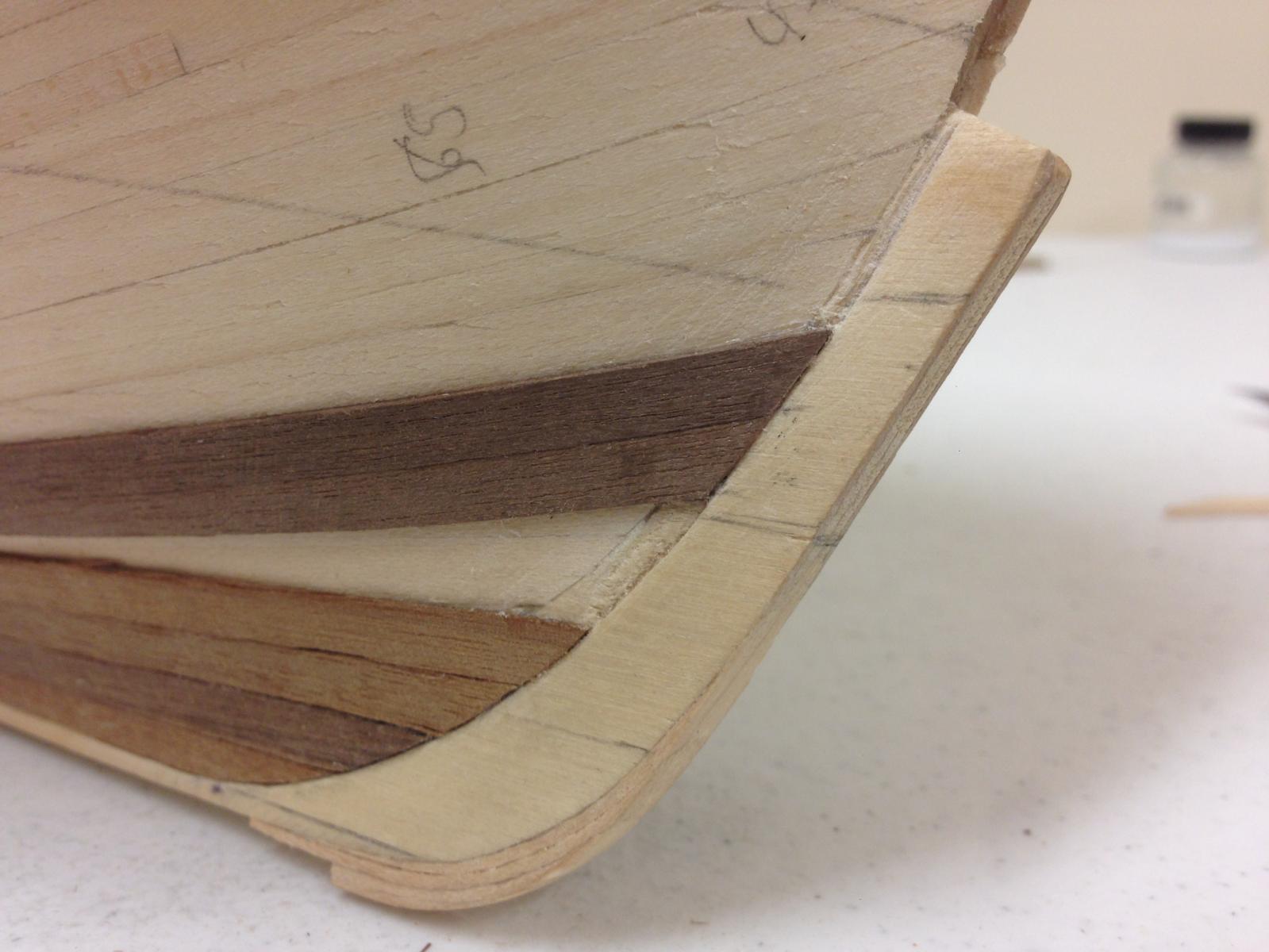
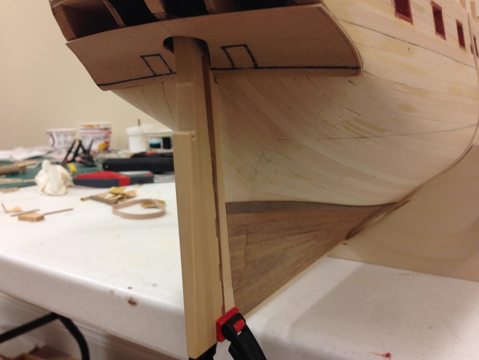
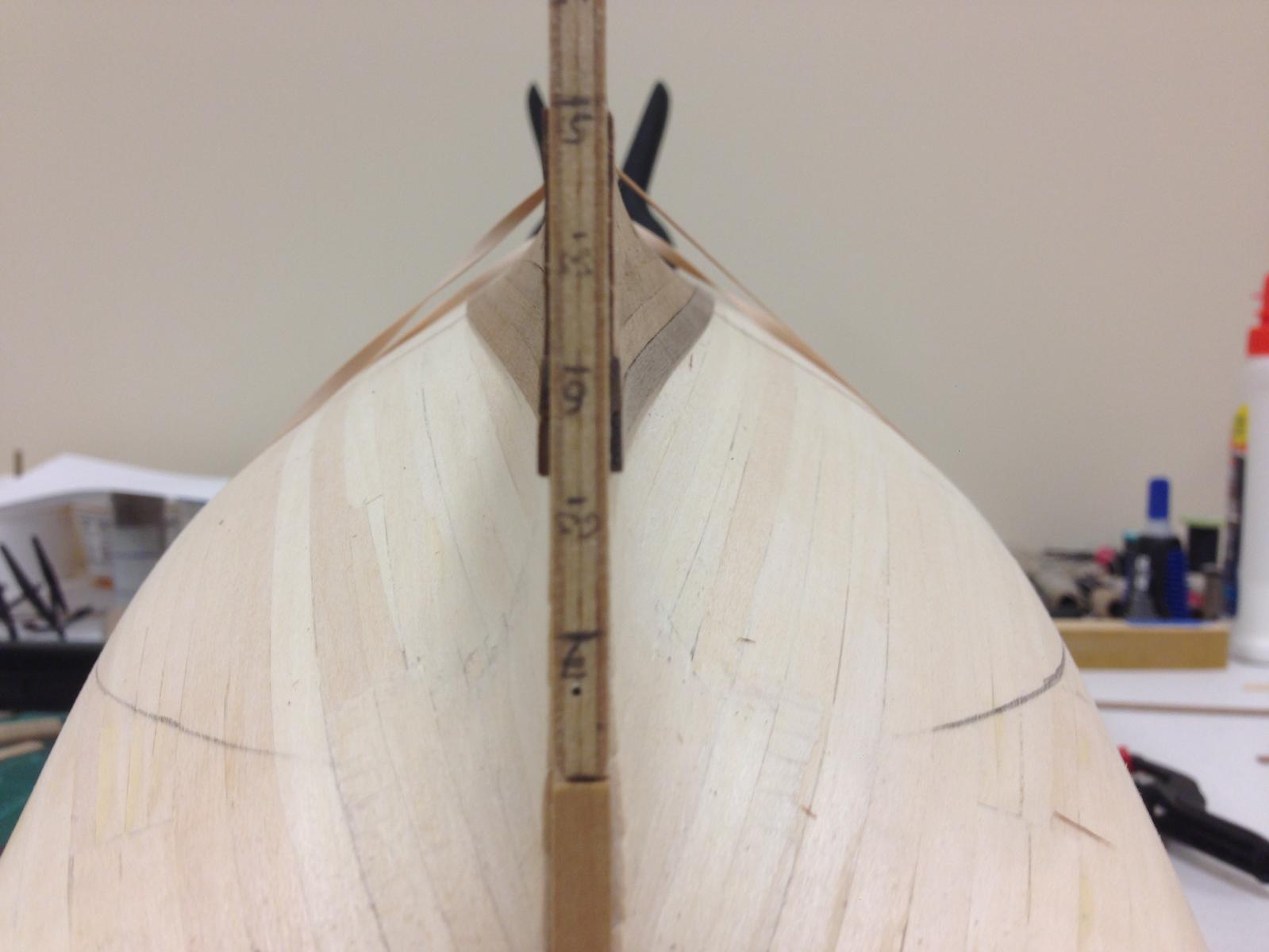
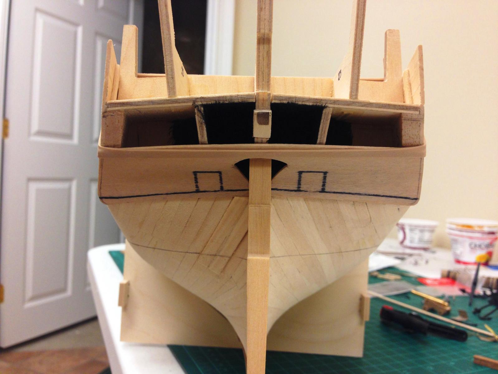
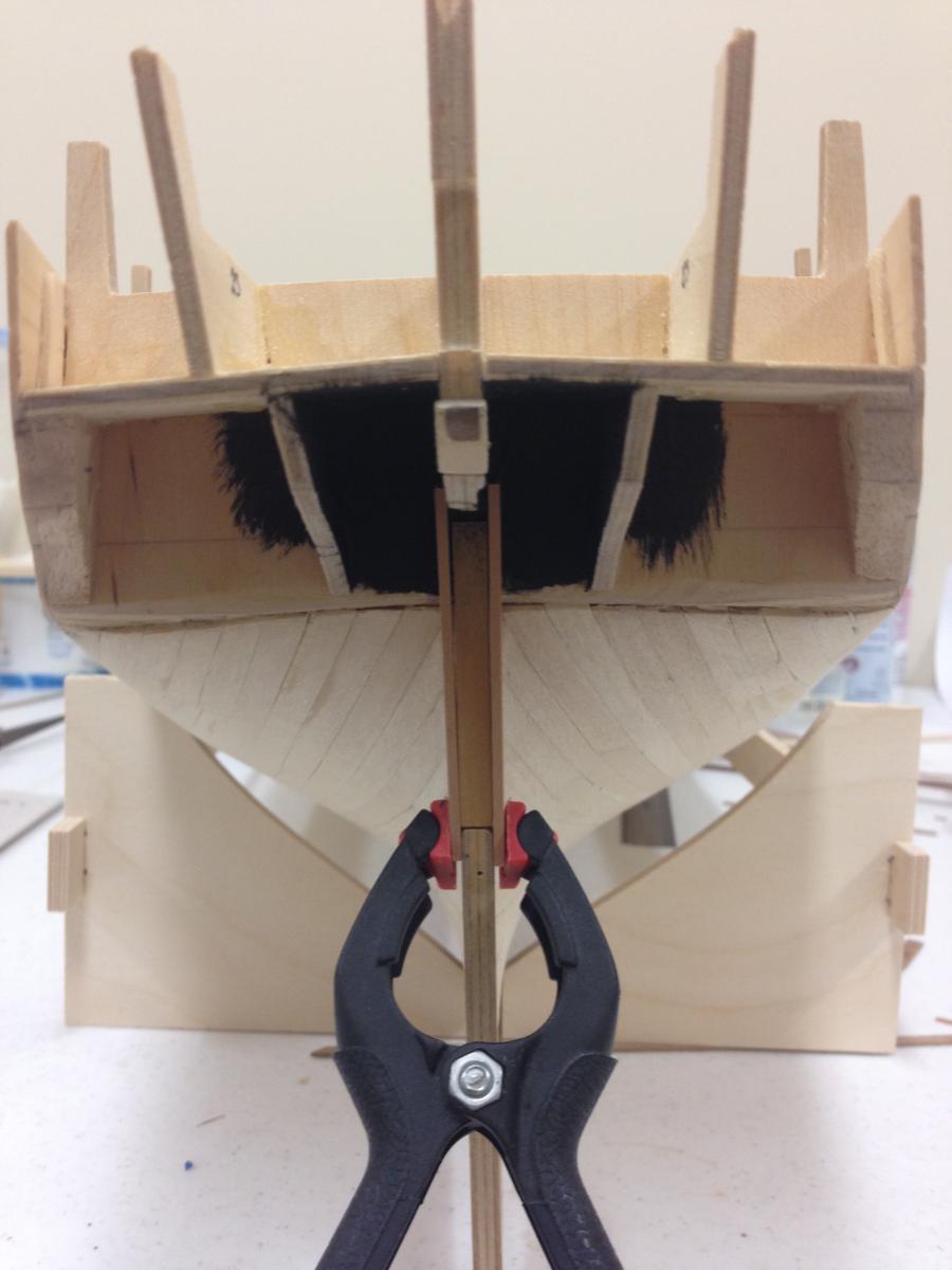
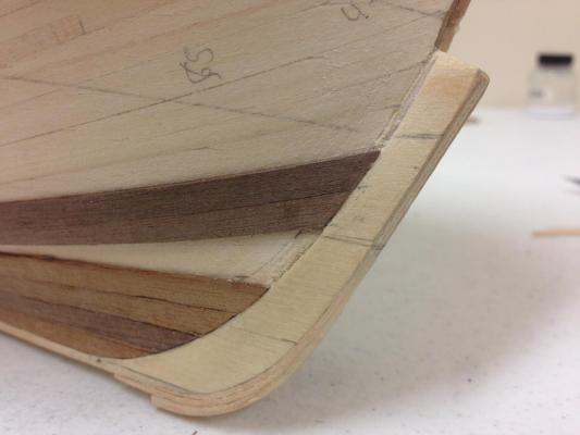
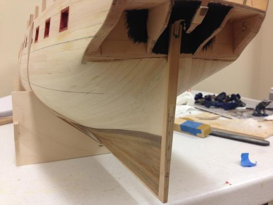
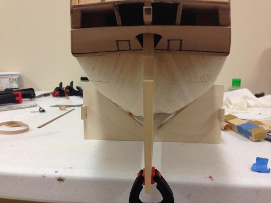
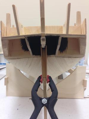
And some results.... Quick report back on the 'double rabbet' approach taken at the beginning of the build, seems to have worked just fine. 1.5mm boxwood sheet cut to the profile of the sternpost, laminated to both sides and then tapered following the rudder profile. Rabbet where planking terminated at the sternpost seems to have turned out OK and I think the extra work will make the second planking in this tricky area go more smoothly....fingers crossed. I also cut away quite a bit of the keel former above the rudder to ensure I'll be able to attach rudder at late stage when pintles are in place. Sternview with rudder in place, lower counter template not yet glued. Question: Do the proportions look about right? All is in line with diagrams in the AOTS, but things look different in actuality. Its easy enough for me to adjust now so please let me know your thoughts

-
Christian - nice to see you back and making progress. You have a truly beautiful model! Its a shame that I missed your initial progress, but will definitely be following from here. I'm still in the very early stages of my Diana/Jason build and moving slowly, so its nice to see another example to look to for inspiration. Thanks for sharing.
-
Nils, love the shot of the forecastle, nice camber to the deck and you planking looks very pleasing. Great and fascinating work as always.
- 2,625 replies
-
- 4
-

-
- kaiser wilhelm der grosse
- passenger steamer
- (and 1 more)
-
The Snake and Diana Caldercraft kits do not include the bulkhead plans so where there are deviations its hard to know which side is "correct" - if either!. Its all solveable, but requires and shimming or cutting down to be done once bulkheads are installed and relies much more on the builder to get a feel for the flow of the hull to get a feel for any corrections. I found this process on Diana to be much more challenging, not because the bulkheads were necessarily any less accurate, but more because small deviations are more noticeable.
-
Nice work Hamilton, nice to have some plans to compare the bulkheads to before installation.
-
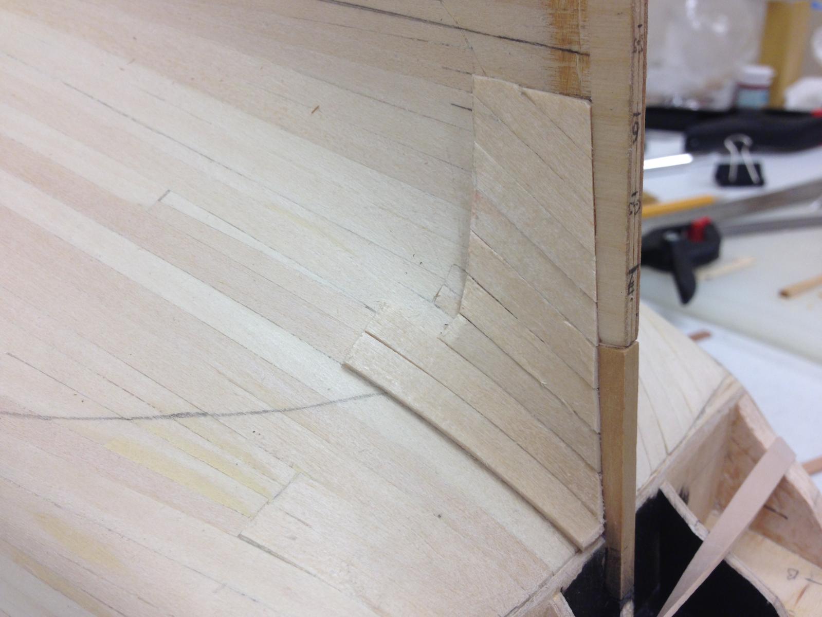
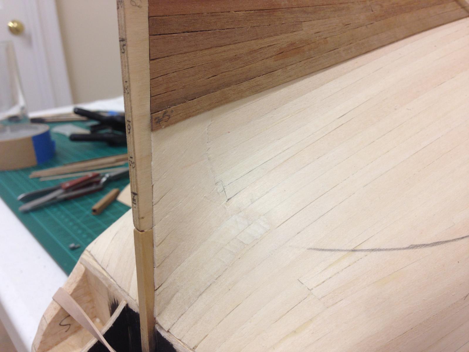
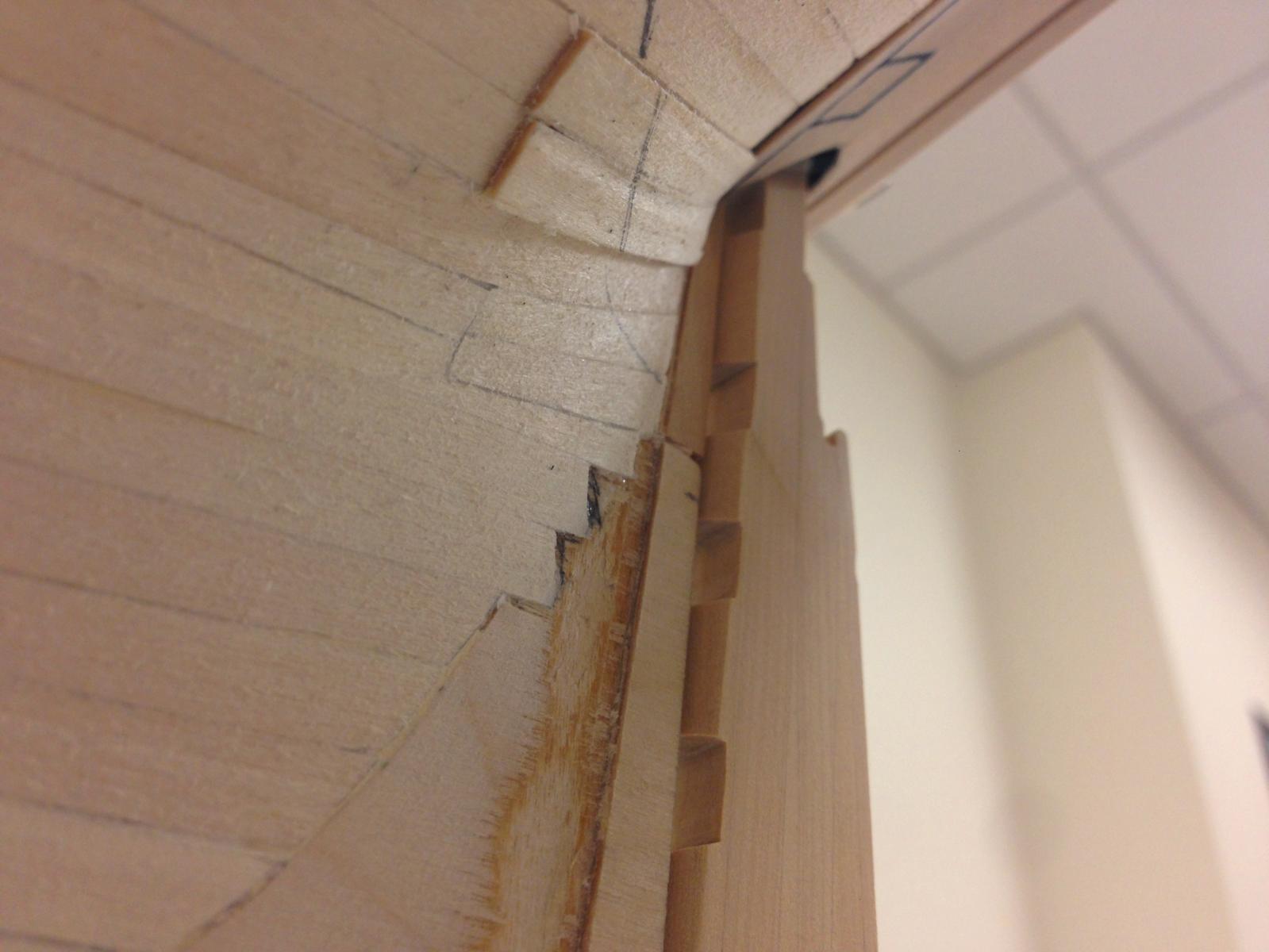
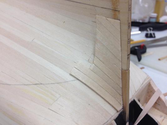
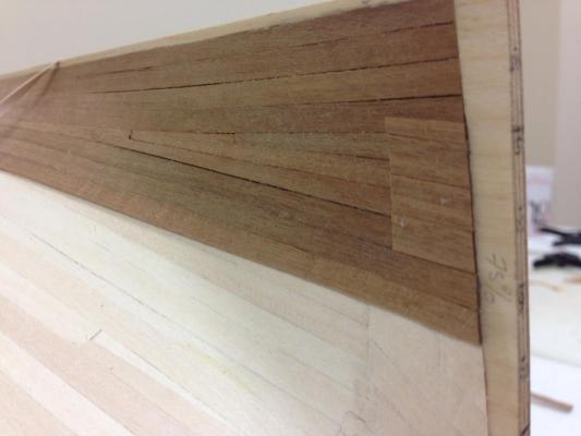
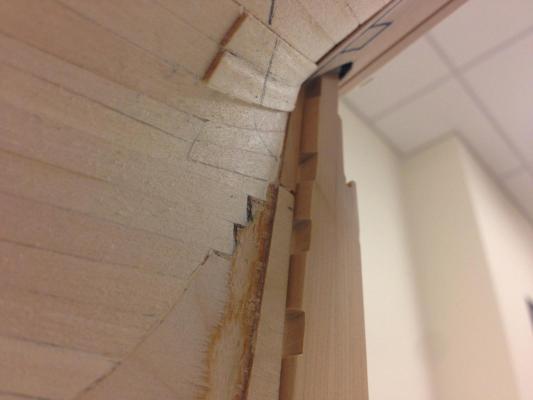
Second Planking phase 1: Finished building up the stern post area with limewood strip to approximately where it needs to be. Once I'm confident that the stern area will work, on will go the lower counter which will allow me to put the wales on. I'm hoping to complete the wales first and then use this dictate the flow of the visible planking rather than install over the second planking. The sternpost was marked off as best estimate of the end state thickness and used to guide planking. I'm trying for a smooth run on the limewood, but then will be building up the second planking in 0.5mm increments to then sand this back as appropriate. I'm using PVA glue for the second planking, its slower but I just don't like using CA glue. There are also a couple of areas where the first planking is perilously thin so any additional strength will likely be beneficial. Not going to invest any more time than necessity requires here - all of this will be covered by copper plates. Limewood glued on but not sanded back. This was a little demoralizing as essentially a lot of this was replacing a lot of the material removed from the keel former for the rabbet and bearding. For anyone taking a similar approach keep this in mind right at the beginning of the build. Limewood sanded to shape and second planking going on... Additional 0.5mm thick strips added where needed for thickness... Pre-finished 'step' look that will eventually be sanded smooth as required before the sternpost itself is shaped.

-
Brian, that is beautifully crisp and precise rigging. Looks like you've used the Syren thread throughout? Well done!
- 831 replies
-
- 6
-
-
- Armed Virginia Sloop
- Model Shipways
- (and 1 more)
-
Thanks Carl, Mark, and the 'likes'.. Ray - great point. I'm somewhat limited in my level of 'precision', basically, if I can measure it on my metal ruler then I'm good. I've noticed that there are (not surprisingly) discrepancies in the AOTS book dimensions and without the plans its a bit of guesswork. Bottom line, I'm using the measurements as a guide but not getting too hung up on it - if it looks right then I'm happy
-
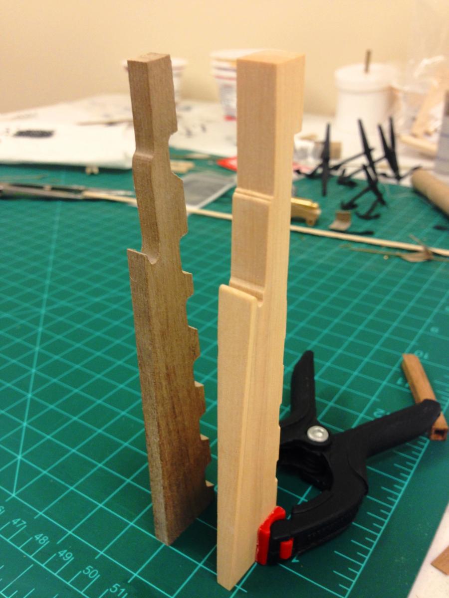
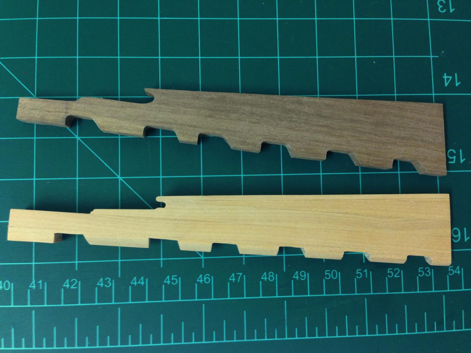
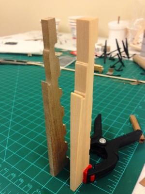
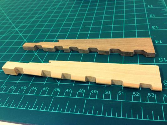
The rudder: One I'd made my mind up to try to reflect an appropriate taper on the sternpost, I realized I didn't really know how it would be shaped, so I decided to make up a new rudder as that is clearly illustrated in the AOTS book, thinking I could then use those dimensions to determine the taper on the sternpost. Bottom line, this was slow going as I don't have a huge assortment of power tools, but I had a lot of fun doing it! 5mm sheets of box were cut into approx. 9mm wide sections to allow final shaping and laminated together. I kept the front and back sections until the last moment so in the event of a catastrophic error I'd have less rework. I completely forgot to take progress pictures, but hopefully its relatively obvious. After studying many diagrams and plans, I tweaked the location of the pintle cut outs to match the AOTS dimensions, the biggest change was the uppermost one, which I raised a fair bit. Overall, very happy with the result compared to supplied part, I'm sure some final fettling will be needed before finally fitting. Should also add a public service announcement, did need to buy a small amount of wood from Jason at Crown Timberyard, - easy online ordering, lovely boxwood, and reached my house approx. 7 days from ordering - great service. The difference in dimensions can be seem compared to kit supplied rudder The rudder head now looks much more in scale within the counter rudder hole. Shots from below show how much of a 'build-up' will be needed to match the rudder dimensions.


-
Hi Bob, seem to remember there being some discussion on this in one of the logs a while ago and just cannot remember which. I had looked for some pictures a while back of Victory's shrouds, and for some inexplicable reason it seems that the starboard side is by far the most photographed. Best picture(s) I could come up with was the following (sorry so small) which does show the free end on the aft side, however it also shows them quite twisted, and messier than appears on plans and Petersson! I'm sure a bit more digging could come up with a better pictures... I don't want to be passing on incorrect information, so if I'm wrong hopefully someone will speak up. It would mean I'd need to redo my Snake shrouds . Port side... Starboard side...
-
Looking great Bob - I'd agree with Arthur, you can lace up the deadeyes anytime, and if you leave a bit of length on them, you can come back and tweak or fix any tension at any time - that way you can re-use your spacers on the other masts. Being lazy, I only made a couple of spacers which also helped with consistency of spacing. In addition to the #3&4 stb shrouds that Arthur mentions, believe the shrouds consistently go anti-clockwise round the deadeye, which means that the free end is on the aft face on the port shrouds, and the front face of the stb shrouds.
-
Hi Hamilton, you pick the most interesting ships, looks like you've made a nice start there. I can't even picture wooden copper tiles, any chance of some pictures? BTW - I think its great that you post the mundane pictures, its good for everyone to get an appreciation for the additional work needed to get in going in the direction you want it, and testament to you wanting to get it right!
-
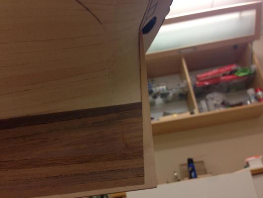
You guys know me better than I know myself... I've been looking at more pictures of completed models and all seem to stick with the 5mm sternpost/rudder thickness....but, the worm is in my head now and I think I'm pretty resolved to try to get it right, just need to figure out my approach. I found some 1.5mm thick wood strip that I had to get a sense for what this would look like.
-
Carl - you're right, I didn't say it well, I'd probably need to add additional planking to the already laid first planking - it would mean adding quite a bit of thickness, maybe 1.5-2mm per side to the 5mm thickness already present. Nigel, there is the rub, there is no provided sternpost. The design of the kit is such that the rear of the plywood keel former IS the sternpost, which is why I had originally inserted the boxwood portion where the sternpost would be visible. The keel is 5mm thick, and I'm estimating from the AOTS diagrams that it should be approx. 8-9mm at the top which seems quite a significant difference, and diminishes to approx. 3mm at the base. Of course the rudder should match this, and this also comes in 5mm sheet. I'd also need to rebuild the rudder in boxwood somehow, I only have a 5mm thick sheet of that.
-
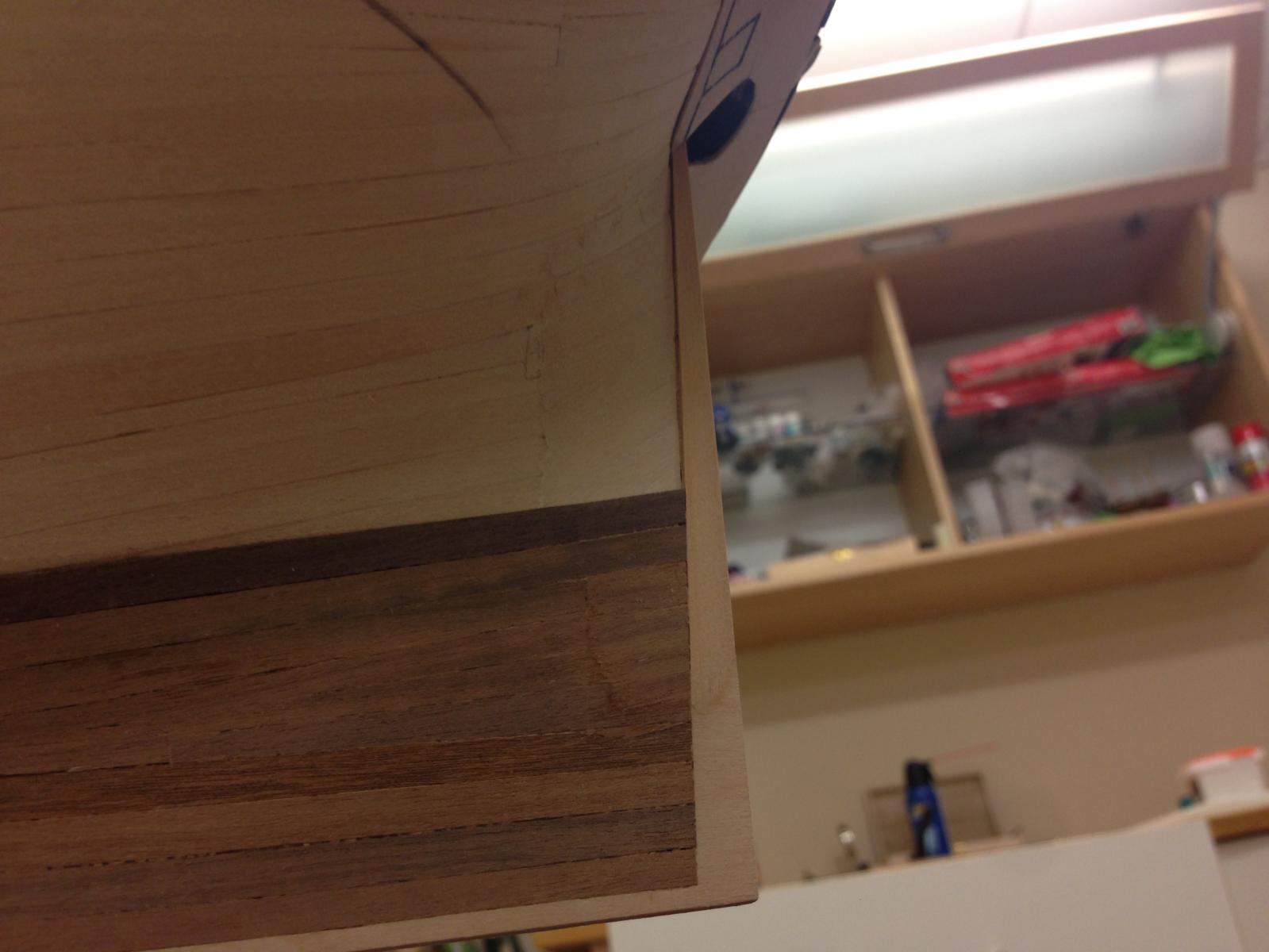
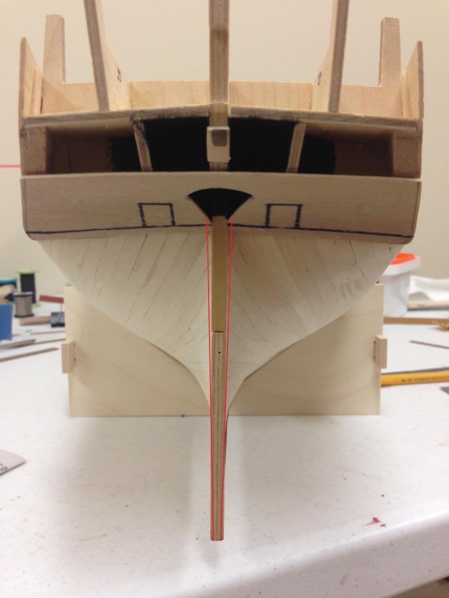
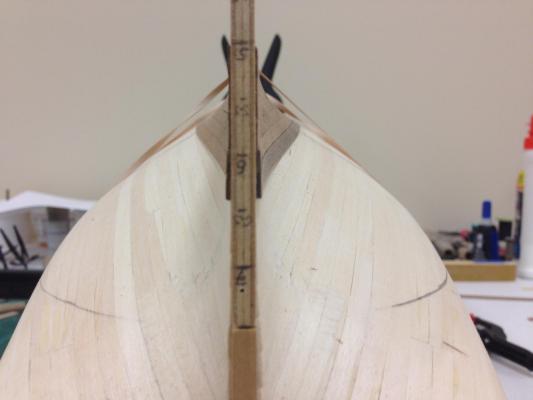
A Sternpost question... Not so much an update as a "request for thoughts". Looking to glue the lower counter template I made earlier in place, but something was not quite looking right comparing to the AOTS. Then it struck me, the thickness of the sternpost should be considerably thicker (approx. 60% by my best approximation) near the top) than the thickness of the keel former (see red lines on picture below). This seems common structural feature so am curious how others have approached this and thoughts on this topic. Options seem obvious, but is the second option really worth the effort ? Very interested in the thoughts and conclusions reached by others. I'm leaning to option 1 as I think option 2 could just be too involved. Status quo, stick with the 5mm width and taper toward the bottom. By far the least effort, but not sure whether this will look too skinny. A rudder coat could mask this as well. Bulk up the stern post accordingly. This would require much additional adjustment to the first planking to ensure second layer sits correctly to new termination, and would also require the rudder to be similarly beefed up.

-
Beautiful Nigel - could be a Monty Python scene right now if somebody walks through the door...but seriously, looks great. You used epoxy, is that for strength? I've seen a few other people reference using epoxy and I'm wondering that I'm doing something wrong by not using it?
-
For some reason, I haven't been seeing the recent updates to your beautiful build. The good news though this that I've had a lot to catch up on...everyone else has already said it, a stunning model you're building here.
-
Martin - somehow I missed your build here, anyway, I'm all caught up and will be following you from here. She looks a real beauty, great work.
- 467 replies
-
- 1
-
-
- fly
- victory models
- (and 1 more)
-
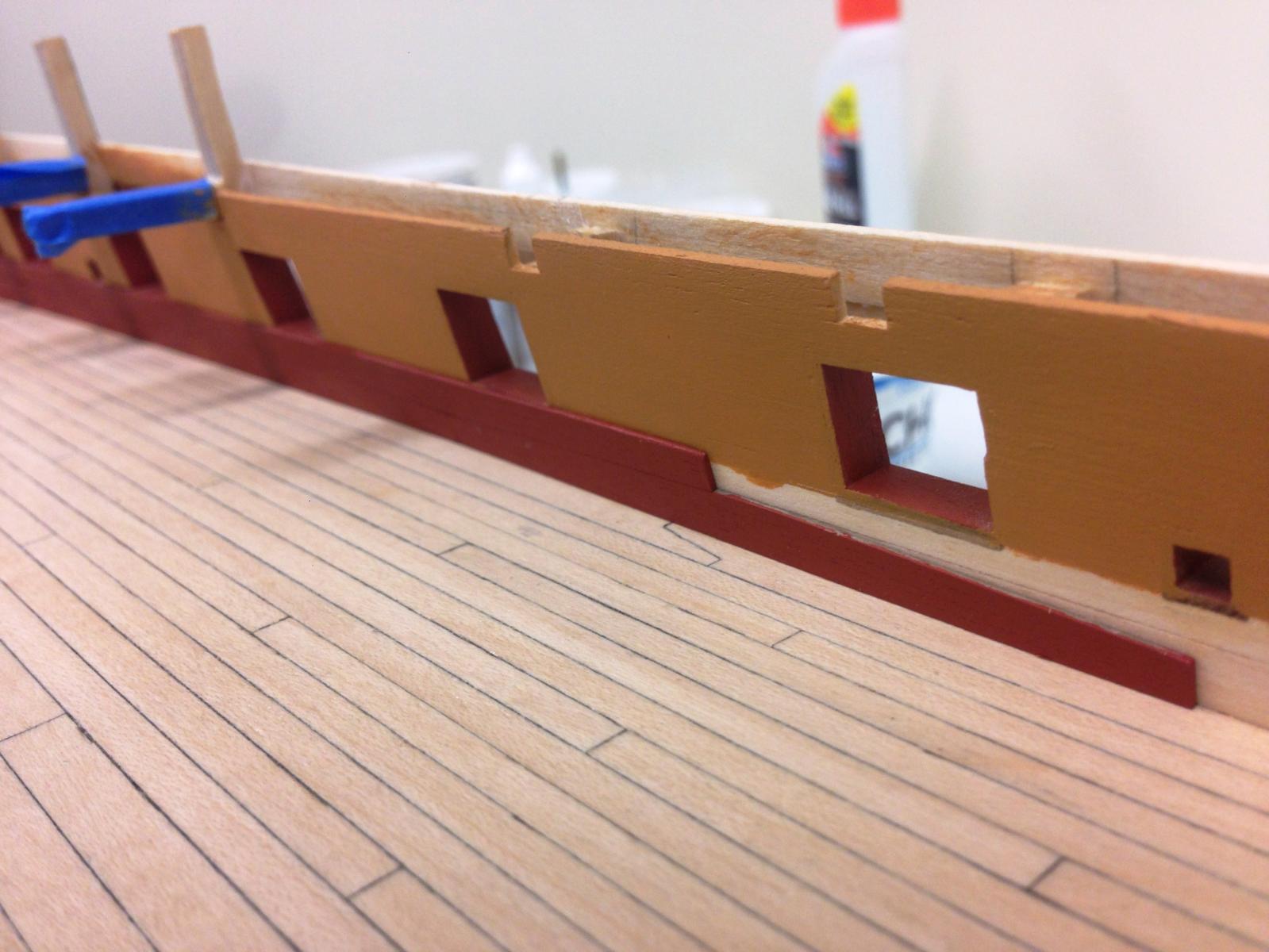
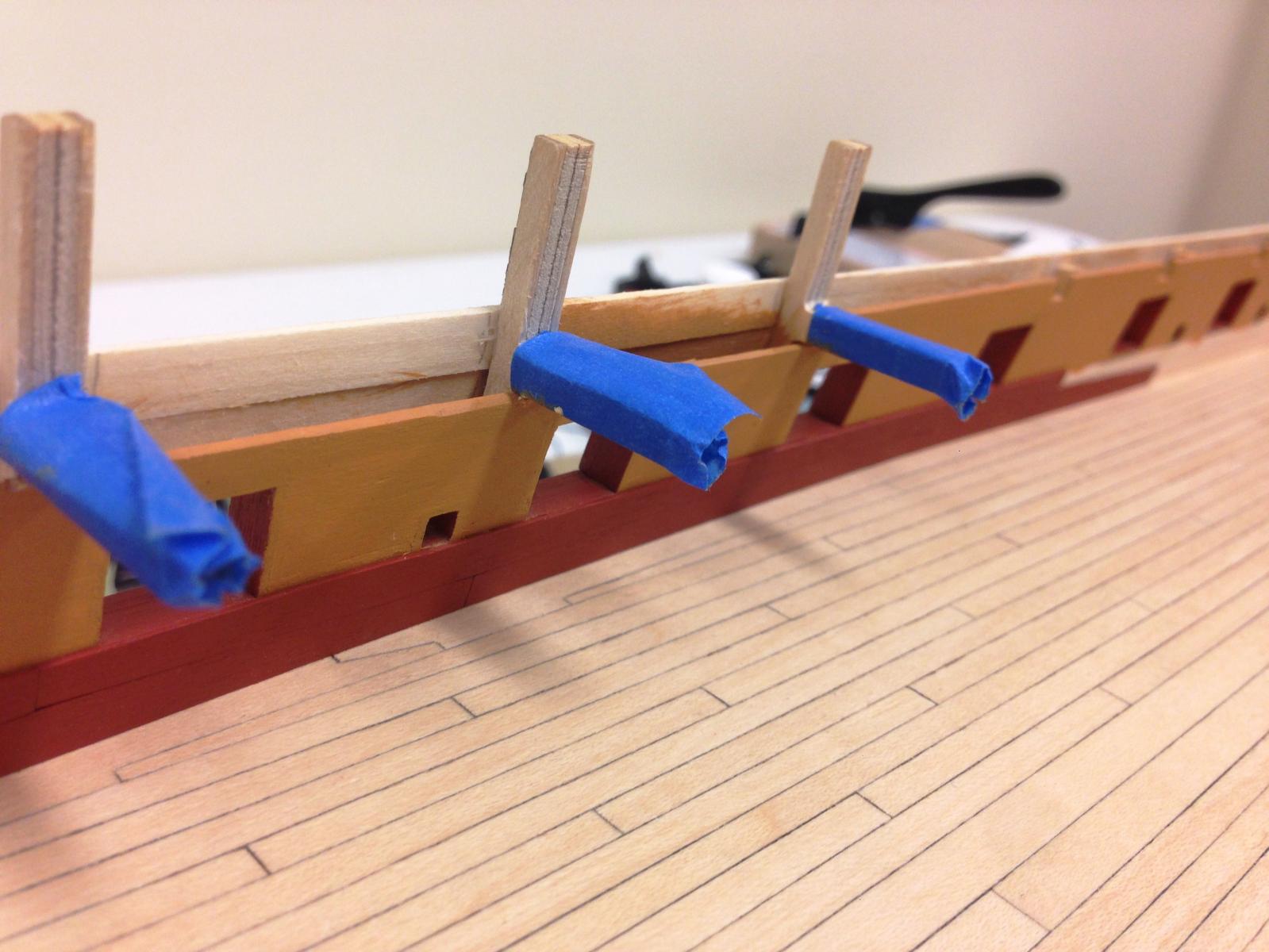
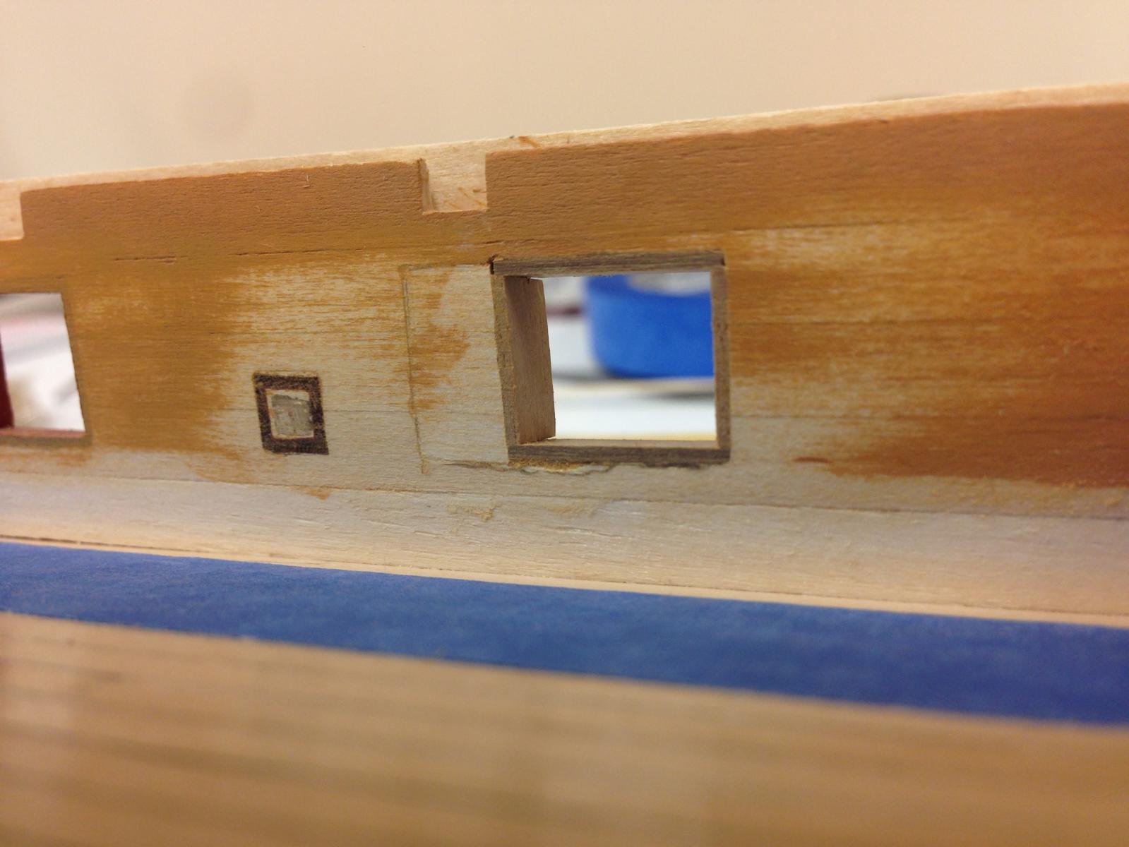
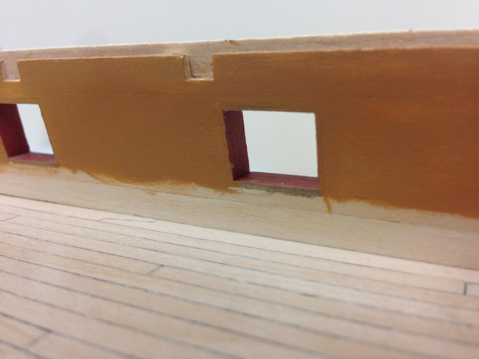
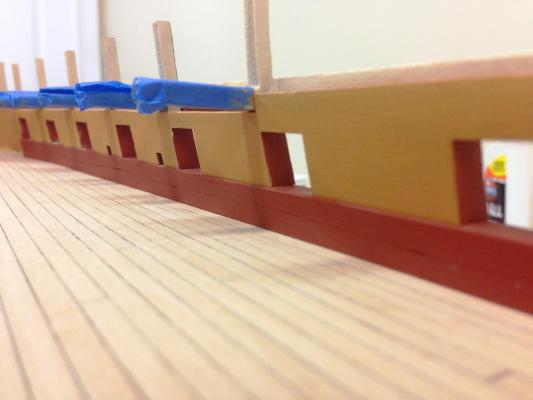
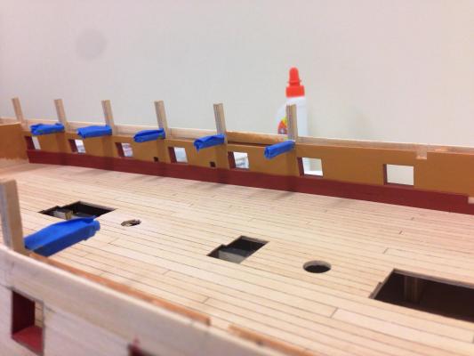
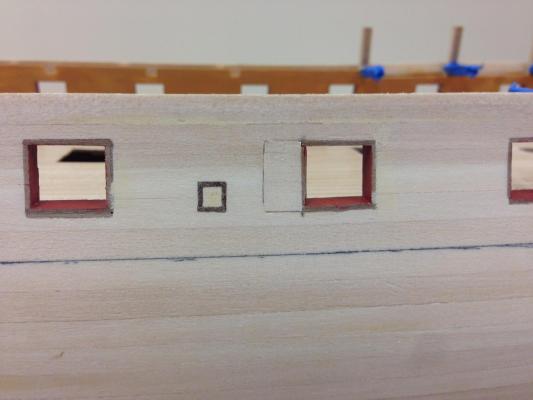
Moving on to adding some spirketting. I just love the look of the NMM Minerva model, something that is increasingly influencing where I think I want to go with this model. One of the features is the contrasting red spirketting against yellow quickwork which I'm looking to replicate here. The primary challenge is that the all the gunport sills should be exactly the same height from the deck - although most are very close, there is a variance of no more than 0.5mm across the range, its enough to present some problems as the contrasting colours emphasize errors. 'Top and butt' Planks were mass produced slightly larger than needed by gluing a number of planks together and sanding to shape and then separating with IPA. These were then individually tweeked to ensure the top of the top plank meets the lower sill and the sweep ports. Although sadly not much of this will be seen, its a good opportunity to build some confidence and safely practice a skill while still making progress. Lots of touchup still needed.


-
What a beautiful collection Ray, they look even better in position on Diana.
- 536 replies
-
- 1
-
-
- diana
- caldercraft
- (and 1 more)
-
Real quick update, the patchwork has been materially completed, think this turned out OK as it will be in an area that will be more visible. Lime strip was used to back against the interior and exterior existing planking to provide a solid base for the patch planks. On the interior, I tried to match the run of the planks to blend it in as much as possible. Next will be (lots of) tidying of paintwork and some more coats of poly on the deck... Exterior... Interior pre- and post- a few coats of paint.


-
Jesse, not exactly experienced in this area either, but this worked for me. I shaped the margin planks as I went and actually glued in position last. Found shaping each plank end first allowed the profile to be transferred to the margin plank and doing it that way also allowed small errors to be corrected as I went. It also meant that in the event of catastrophic failure, would be relatively easy to make another one. Think there are some pictures in my log. I avoided tapering the deck planks for similar reasons as I just could be confident I'd be able to get to the appropriate tolerances to look right and get good symmetry, luckily on 'Jason' though the areas where this would be most noticeable will be obscured by upper deck so I may try in the future....that being said, I believe the time period in question is when there was a transition to more industrialized production which resulted in using straight planks rather than individually shaped ones.
- 1,306 replies
-
- 3
-
-
- syren
- model shipways
- (and 1 more)
-
Cheers gents...character building isn't it? Carl - luckily its only one port per side that's out of position, even so, its quite a bit of work to fill the hole solidly and then reline and I've been leaving glue plenty of time to dry as I go. I'll leave the explanation of how I noticed it to a future post as that is a another story in its own right.
-
Very nice indeed Jesse, the wood tone looks great against the black.
- 1,306 replies
-
- 6
-
-
- syren
- model shipways
- (and 1 more)