Beef Wellington
-
Posts
2,249 -
Joined
-
Last visited
Content Type
Profiles
Forums
Gallery
Events
Everything posted by Beef Wellington
-
 Wayne, very nice looking ratlines. Have to agree that the loops look just a little bulky. Did you consider using thinner line to do the serving to keep the same look? Using regular thread (would need to check exactly what) worked well for me following the dimensions on the plans - I was happy at least. Nothing like a nice stack of served shrouds/backstays, looks like mine ended about half way up but didn't think it looked too odd... http://modelshipworld.com/index.php/topic/509-hms-snake-by-beef-wellington-caldercraft-scale-1-64-first-wooden-ship-build/page-43#entry213341 Interesting that you picked HMS Pelorus as a candidate for next build, she was one of the few Cruizers that was ship rigged (at least for a period) so could be built directly from the kit and be authentic. Also some nice paintings to follow and refer to after the storm.
- 366 replies
-
- 4
-

-
- granado
- caldercraft
- (and 1 more)
-
Jonny, I'd double check the spacing on the ratlines, 1cm at 1:64 would be 64cm at full scale which seems a little much, think it should be closer to 4-5 mm. Easy solution would be to add a ratline between your existing ones.
-
Forget exactly what I did, but I would advise fitting the futtock stave in the correct position before you do all of the ratlines - that would allow you to adjust slightly the separation of the ratlines so they finish correctly at the futtock stave. I just trusted my eye rather than working with scientific precision.
- 1,144 replies
-
- 1
-
-
- snake
- caldercraft
- (and 1 more)
-
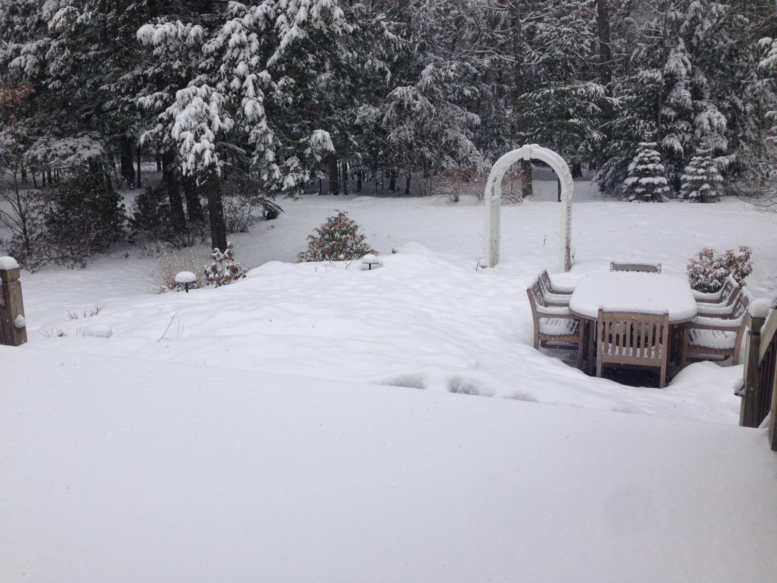
Have started the gunport linings, this will be slow. Fine tuning the ports so they align appropriately is the order of the day. The technique I'm using is to first install the lower cills, and to ensure that the cills are horizontal athwart-ship am using a strip of wood to ensure it sits flat on both sides. Lots of double checking to ensure that position is correct. Once lower cill is fixed, the upper is glued using an appropriately sized spacer to keep upper and lower cills parallel. Side linings added last. And finally, happy Spring everyone! I keep mentioning waiting for warmer weather to get some good sanding done on the hull.....well, this is the scene this morning, looks like I'm still waiting....

-
That look great Jonny, good thinking and very creative solution!
- 215 replies
-
- 1
-
-
- convulsion
- caldercraft
- (and 1 more)
-
Thats looking very nice Stergios, well done
-
I've ordered quite a bit from CMB and have always been happy...until my last order a few weeks ago. Items were missing,and multiple wood strip sizes ordered were the wrong dimension (e.g supplying .5mm thick rather than 1mm, or 5mm vs 6mm). Rather annoying, but they seem willing to fix the issue and I won't hold one mistake against them. Wonder if they've had some staffing issues, seems my issue was not isolated.
- 215 replies
-
- 3
-
-
- convulsion
- caldercraft
- (and 1 more)
-
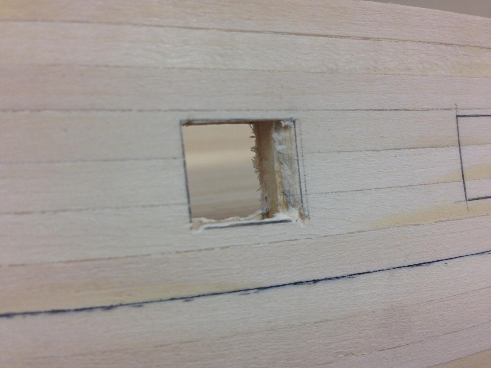
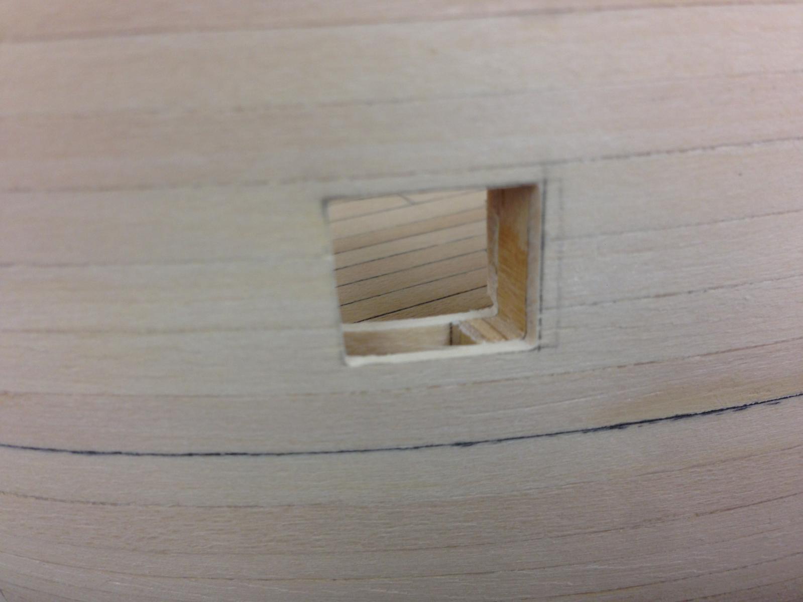
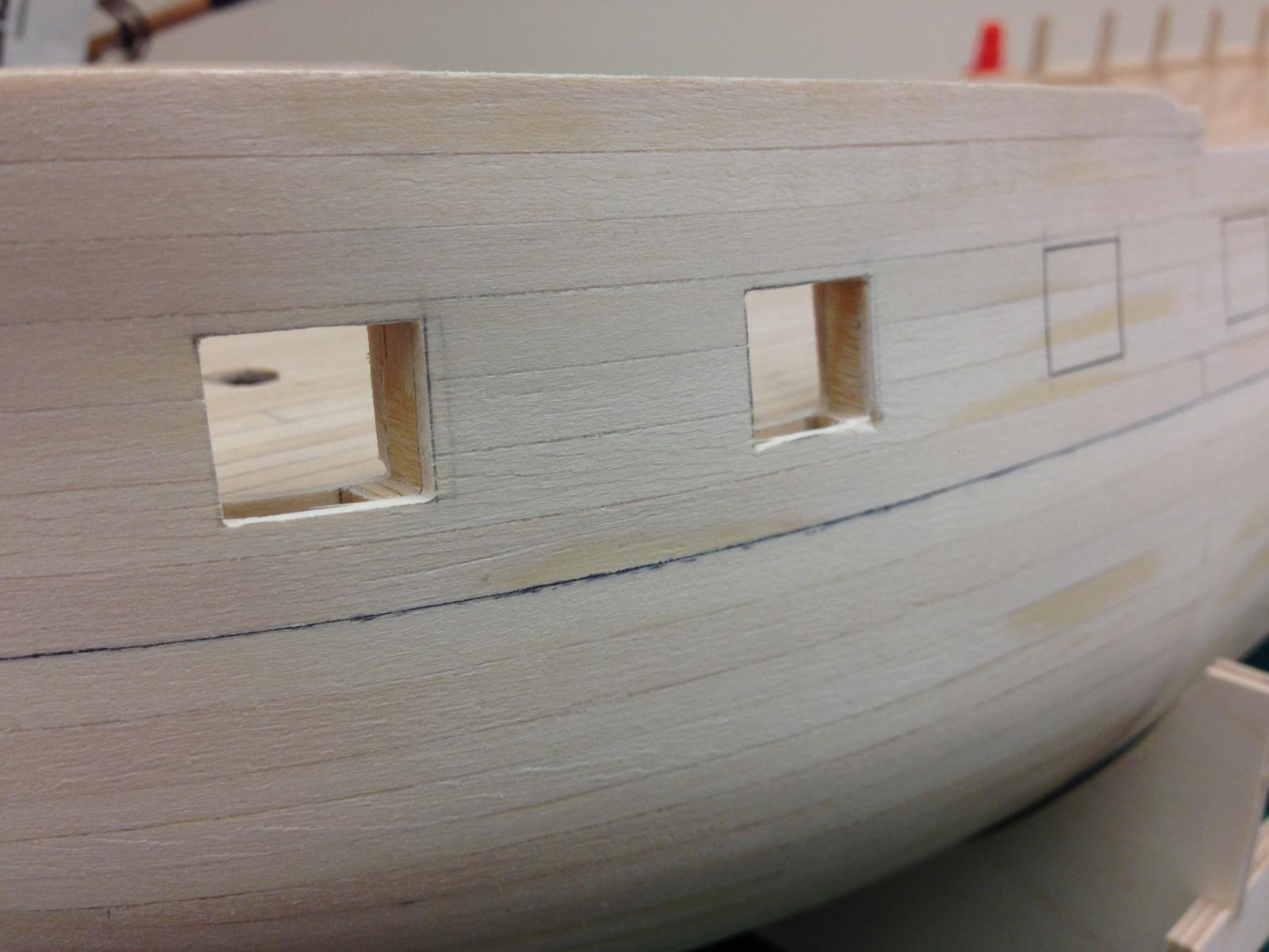
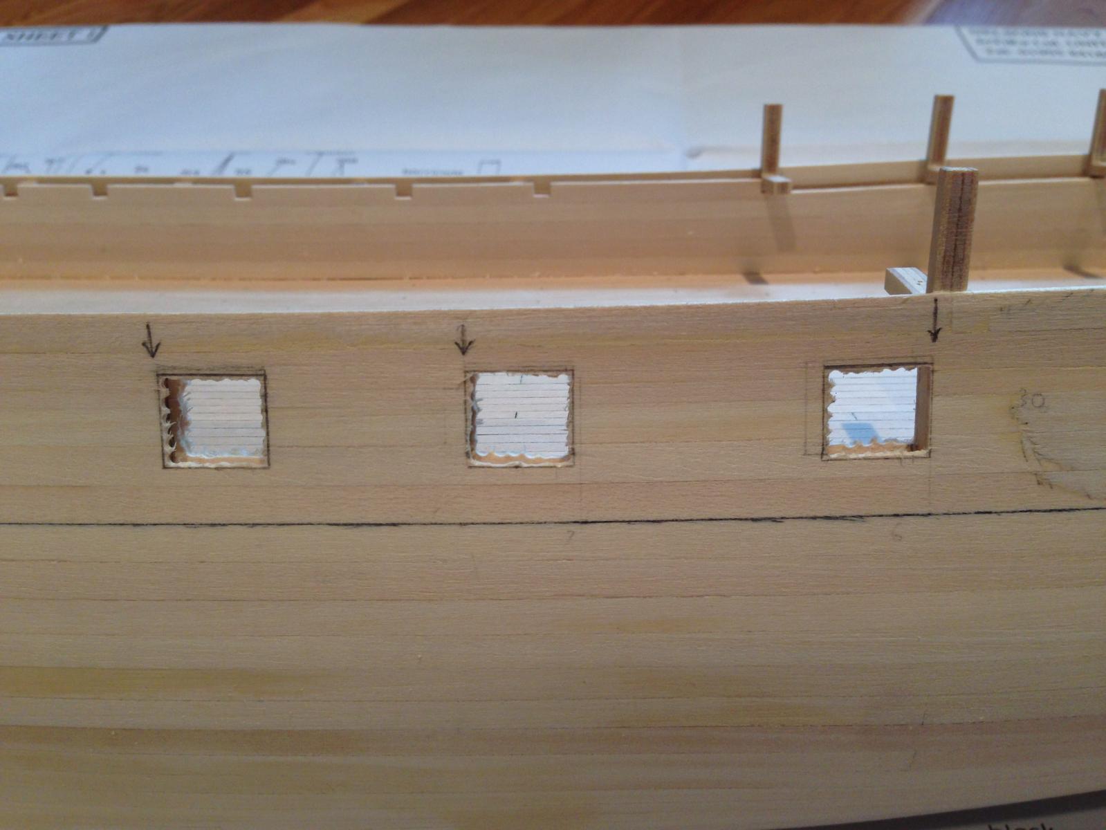
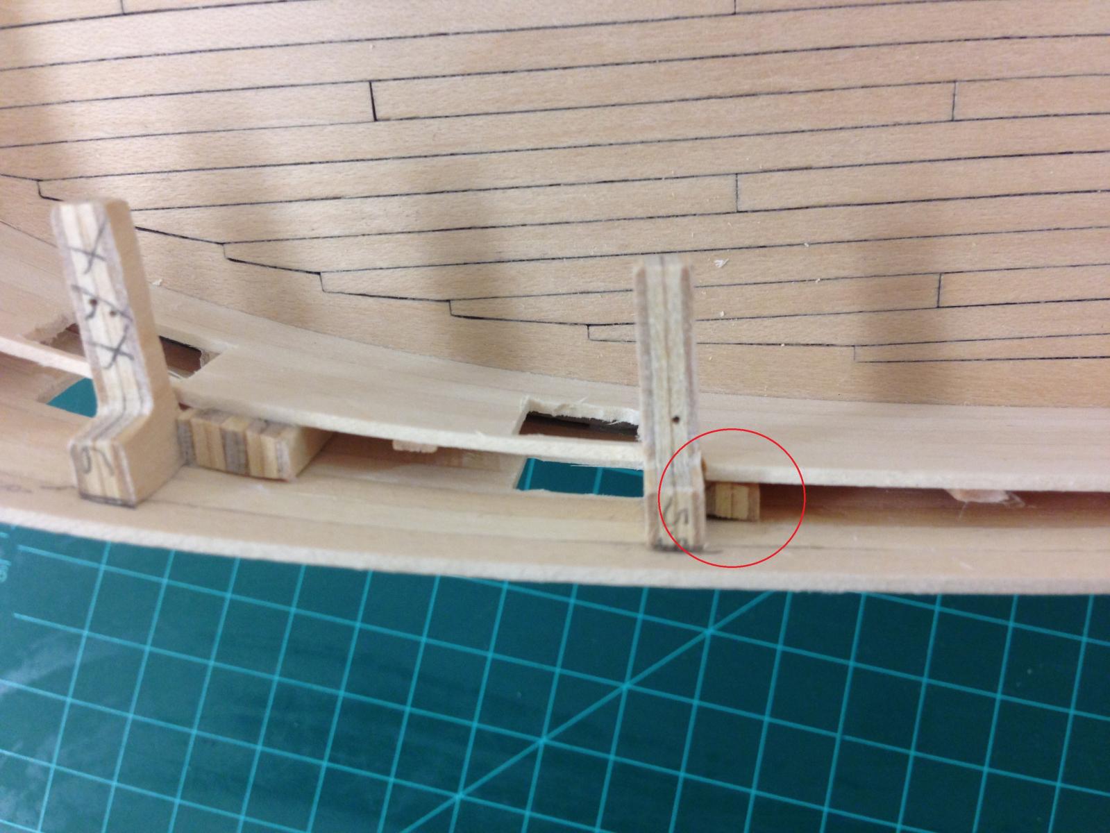
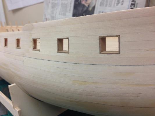
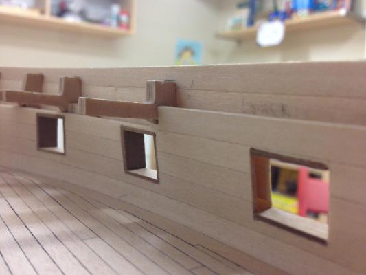
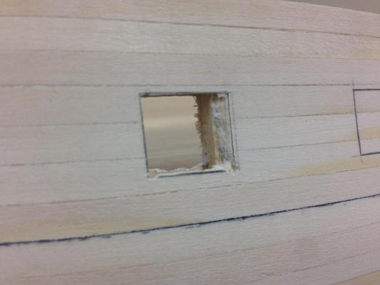
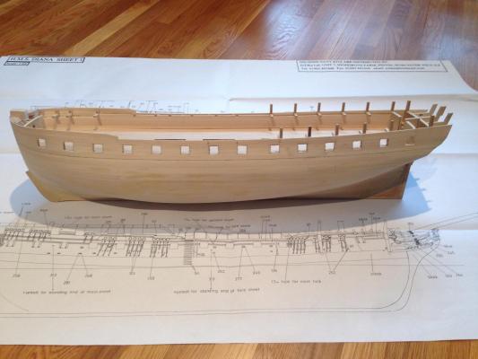
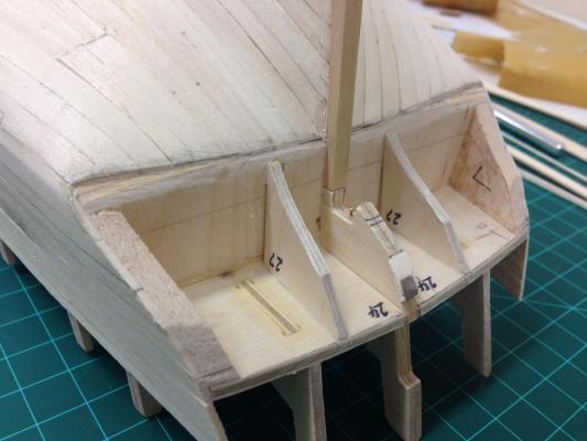
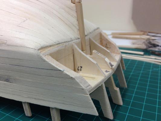
Thanks Jim and Sjors, appreciate the kind words, it was a long time coming and still needs some more sanding to get it where I want it to be. I'm going to wait for some warm weather as I find it quite relaxing sitting outside with a suitable beverage sanding, and theres no push to rush it. Gunports Cracking on with the gunports. This seems to be yet another problematic area with this kit, and here was my approach to hopefully assist other builders of this kit (My thanks to Ray who first trod this path and whose shoulders I'm standing on). The instructions are no help here, and the plans inaccurate. I used the AOTS extensively to estimate as best I can the dimensions, and this required plenty of tinkering. The supplied template is a waste of time as it forces the ports to be square, rather than the bottom cill following the sheer of the deck. Bulkheads 10, 11 & 12 are key to laying out the ports as these bulkheads dictate the positions of gunports 7, 8 & 9. Not mention in the instructions/plans is that gunports 8 & 9 are spaced farther apart than all the others, which are equidistant. The arrows indicate the edge of bulkheads indicating the potential extremities of the ports, 7 & 8 are 30mm apart, 8 & 9 37mm. The remaining ports were then marked to be 30mm apart (which does actually match the supplied template). The edge of the plank was used to determine the appropriate height. This resulted in two problems, the first was expected, the second not. I had suspected that the gunport 1 would interfere with bulkead 4, and had build up additional material so this could be cut away without (hopefully) critically weakend the structure. The unexpected problem came with gunport 2 and bulkhead 5 as these coincide. I was determined to have equally spaced ports, so resorted to some emergency surgery, basically cut some spare 5mm ply cut approximately to shape and inserted between the bulwarks and against bulkhead 5 - the same approach taken before planking for bulkhead 4. Plenty of glue was used to secure this as strongly as possible. Once dry, the ports were cut and fully and trimmed to approximate shape. First picture is gunport 1 (showing how much of the bulkhead is compromised), followed by ports 1 & 2 showing the same Finally the overall shot showing how alignment looks, still work to do here but starting to look like a ship rather than a bathtub! All ports are 30mm apart, except for the aforementioned 8&9. I'm a happy camper.


-
Mark, I was about to give you a dollar for every time I referenced the AOTS book, but guess I can't now :-) Yes, I have it and am referencing it extensively. The side profile on pages 68 and 69 show the gunport lids (cut cut back planking) and the un-lidded ports exactly the same size which I didn't think was correct as you point out above, of course printing at this scale makes a hard analysis difficult. Thanks for helping with my question!
-
Thanks for kind words Wayne, Eamonn, Carl, Mike and the 'likes'... I do have a couple of question that may be very basic but I'm struggling to answer: Should the external dimension of open gunports (i.e. without lids) and those with lids be the same (which would mean that the actual dimensions of the port aperture would be slightly smaller for those with lids because of the lip)? Or, should the aperture dimensions be the same, which means the ports with lids are slightly bigger Should the lower edge of the port be parallel to the deck or the keel and should the sides of the port be perpendicular to the keel?. (The former resulting in a slightly trapezoidal shape toward stern and bow). Hope this makes sense, any help would be much appreciated.
-
You got sweet deal there Wayne! Wondered if you'd considered Chucks other projects to the Cutter Cheerful,the upcoming Winchelsea?. Of course I'm partial to Cruizers, so you can't go wrong really.
-
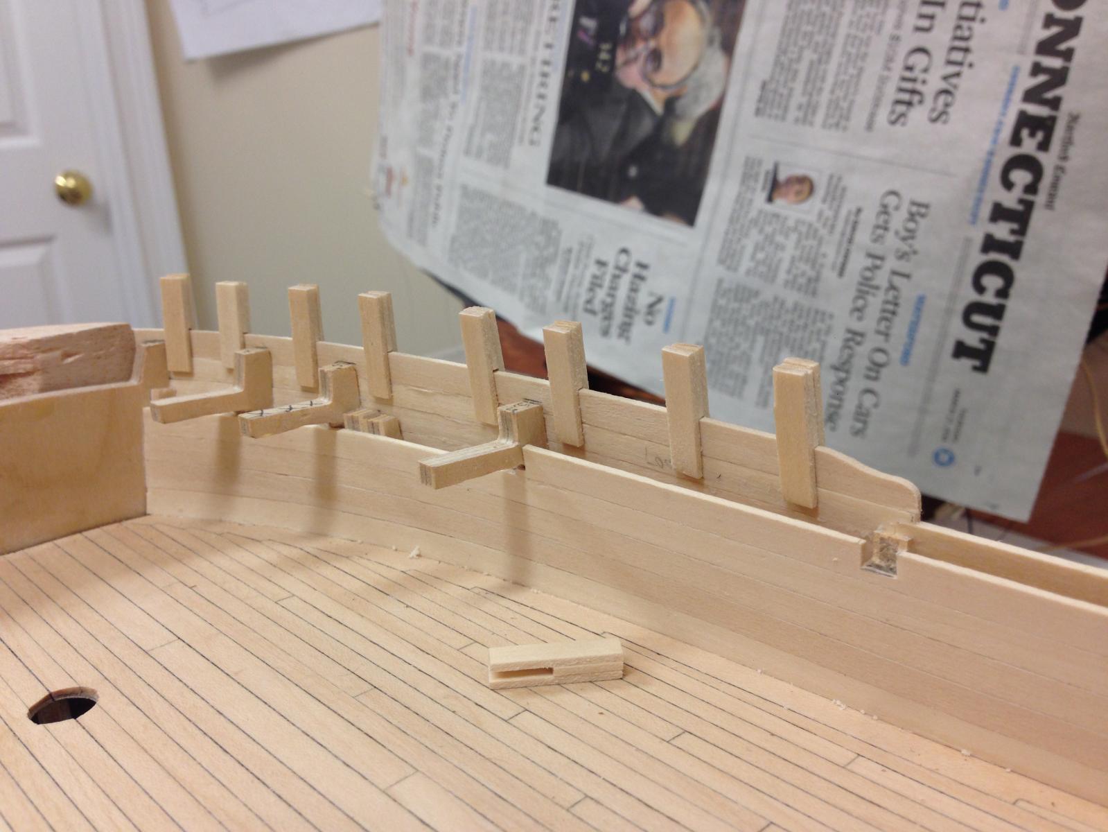
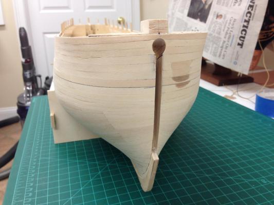
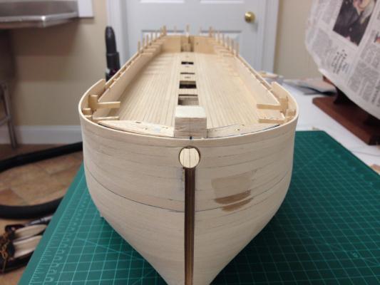
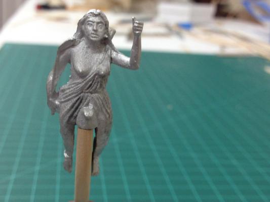
Cheers Guys for the comments and likes, its nice to share a journey with friends. Sjors/Mobbsie - its not an exact replica of me, I had to scale down the pecs to fit Well, a major milestone arrived slowly. Finally the first planking is complete. This time the bow presented me a few problems to solve, all self inflicted because I've deviated from the kit. Because I had decided to customize the bow so I could fit the bowsprit through rather than sitting in a notch on the stem, it essentially took away any anchor points for the fo'c'sle bulwark. The solution I used was to shape some balsa blocks to the appropriate shape and temporarily mount on top of the bow filler blocks, this allowed the planks to be given the appropriate curvature (after soaking) and then securely glued edge on the plank above and below (Hoepfully this will also provide some protection during upcoming phases). To ensure that the top of the bulwark has the right shape for the plansheer, I needed to shape the uppermost strips lower edge to key onto the plank below. Because this strip would be the most susceptible to damage, I used one pre-shaped strip curved completely around the bow. The bow on this ship looks deceptively simple but has some tricky curves, but even in this rough state the lines seem to be showing through very pleasingly. Note that the two shaper blocks are very slightly different height which gives the illusion that the top strip is not level, but it is....I must have checked it a million times. A scaled copy from the AOTS Diana book to get the correct shape of the bow and many diagrams cross referenced Finally a technique I found very helpful, but unfortunately not until I was nearly done. To keep planks edge on during planking I built these little 'U' shaped pegs out of some extra lime strip (the length of the slot is slightly deeper than the width of a strip) which can be used in many places to help keep strips edge on in some the tricky curving areas at the bow. The uppermost strip is only approximately shaped at this point, I want to wait until the deck is on the determine final dimensions. In the waist, I once again deviated from the instructions and carried the planking 2mm above the top of the bulkheads rather than stopping at the top as indicated in the instructions to allow for the thickness of the 1mm false deck and 1mm deck planking. Any excess should be easy to remove if necessary.

-
Looks sweet John. I wonder how rat boards compare to doing rat lines :-)
- 2,250 replies
-
- 2
-
-
- model shipways
- Charles W Morgan
- (and 1 more)
-
Looks like my post crossed with Jhearl's Jonny, I've seen some people draw lines on a piece of card to assist in the alignment which they place behind the shrouds. Here another approach which I used, basically use a couple of spare strips to help get the ratlines with equal spacement. The other advantage of this is that the strips together with some pegs hold the shrouds in place - otherwise the tendency is for the ratlines to pull the shrouds together, even so, this needs constant attention. http://modelshipworld.com/index.php/topic/509-hms-snake-by-beef-wellington-caldercraft-scale-1-64-first-wooden-ship-build/page-36#entry168714 I think its fair to say that the ratlines seem to be few peoples favourite steps as it can be quite tedious, I found I didn't mind it, but I'd definitely recommend not trying to rush it. Use clove hitches as these can be adjusted if things go awry, and don't be afraid of re-dos. I found a glue call G-S Hypo Cement to be very effective on rigging, it remains somewhat flexible once dry and is clear. I personally don't like using CA glue on the rigging as it spreads unpredictably and seems to result in hard sections that look unnatural, in addition to changing the colour of the line. I've used watered down PVA glue on the rigging once complete to secure any other knots/hitches - its also has the benefit of helping get rid of any 'fuzzies'.
- 215 replies
-
- 3
-
-
- convulsion
- caldercraft
- (and 1 more)
-
Jonny, I'd recommend checking out www.cornwallmodelboats.co.uk. They'll have pretty much anything you need, I've had great service from them even shipping to the US. Postage will be cheaper for you and probably all around it would save the cost of petrol and risk of disappointment.
- 215 replies
-
- 1
-
-
- convulsion
- caldercraft
- (and 1 more)
-
Chuck, looks like a great start, I too am very interested to see how you progress with this kit - kit framed models intrigue me.
-
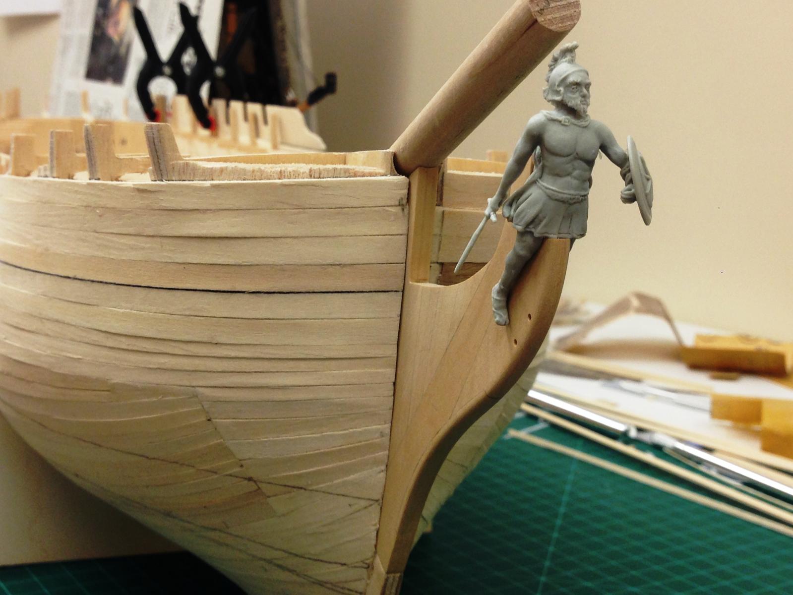
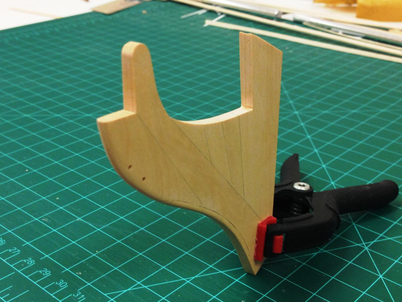
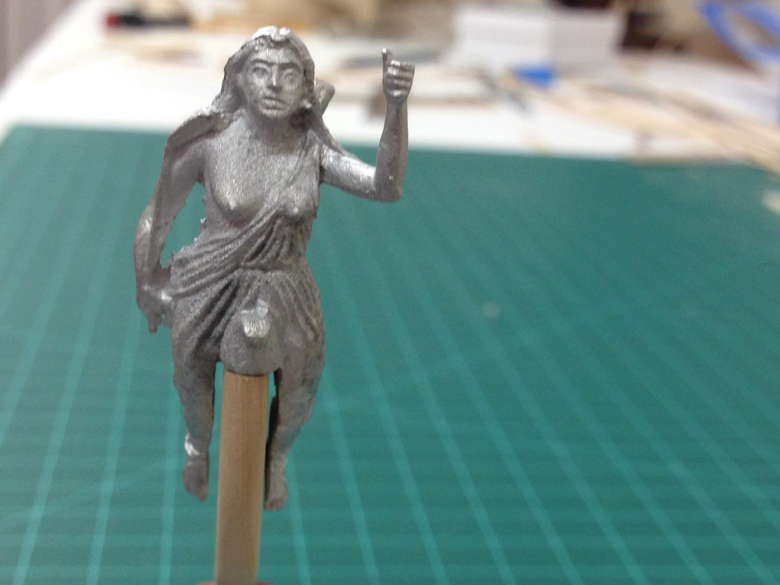
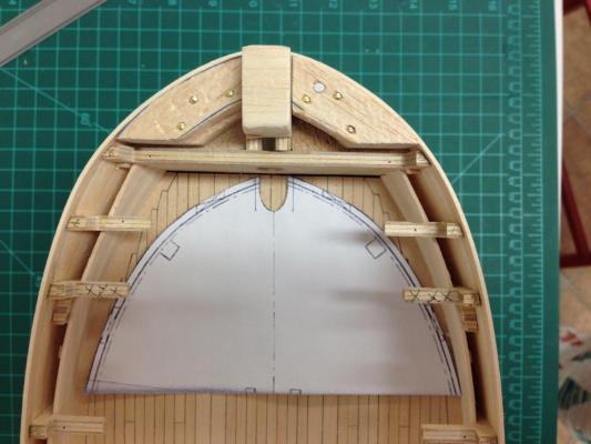
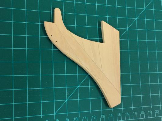
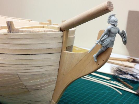
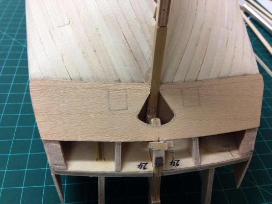
Bit of a diversion while I continue to wait for some more Limewood from CMB. I had planned to replace the plywood false keel stem with boxwood, originally I was going to simply cut out the replacement shape. However, I though this would be a good opportunity to do a little 'scratch' building to give me a flavour for it. I followed the diagrams in the AOTS book, although simplified them slightly (using enlarged scans as pseudo plans while reconciling key dimensions back to the kit to ensure things stay in line). Took quite a few days to do (a full framed ship would clearly be out of the question for me!), its certainly not up to Chuck's standard but overall I was really happy with the result for a first attempt. I lightly used a pencil to highlight the seams to a small degree without wanting to overdo this. Unfortunately, I suspect I will be painting over 75% of this, but it was great experience. I rounded of and tapered the knee of the head using approximate guidance from the FFM book 1. I think this should be tapered more, but I stopped where I did because it resulted in a nice snug fit for the figurehead I plan to use, any more would have resulted in gaps. I rounded the leading edge, and will wait to cut the gammoning slot until I'm confident of the placement of the head rail features. You can see the comparison below between the supplied Diana figurehead which is clearly made to straddle a 5mm knee and result in gaps. I purchased the figure head from Syren when I bought the kit. Everything in place (dry fitted for now). Took some adjustment to ensure I the bowsprit would sit correctly and clear the figurehead. Also have addressed the lower counter at the stern. I got quite aggressive and cut back the transition between the lower counter and the planking to ensure this drops and sweeps forward as it appears to in the AOTS book. I'm only going to use 1 set of the lower counter shapers Premade a lower counter sheet which I though might work better than simple planking. Looks like some adjustment will be needed as the keel former extends into the hole for the rudder. I've got my approach laid out for the upper counter and stern fascia which will probably deviate from what the kit suggests...but thats a story for a future post


-
Jonny, maybe some photos would help come up with some additional ideas. I'd recommend fixing it now before you do anything else, the worst thing would be to 'fix it' and continue and then have it fail again right at completion when there will be far more wasted work and possibility of larger extent of damage. A stitch in time saves nine....just my initial reaction.
- 215 replies
-
- 3
-
-
- convulsion
- caldercraft
- (and 1 more)
-
Ray - thanks for the tip on the jeers, not got there yet but they've always appeared to look very tricky to get right and you nailed it. You look to be getting very close to completion Ray, dare I ask what is next?
- 536 replies
-
- 1
-
-
- diana
- caldercraft
- (and 1 more)
-
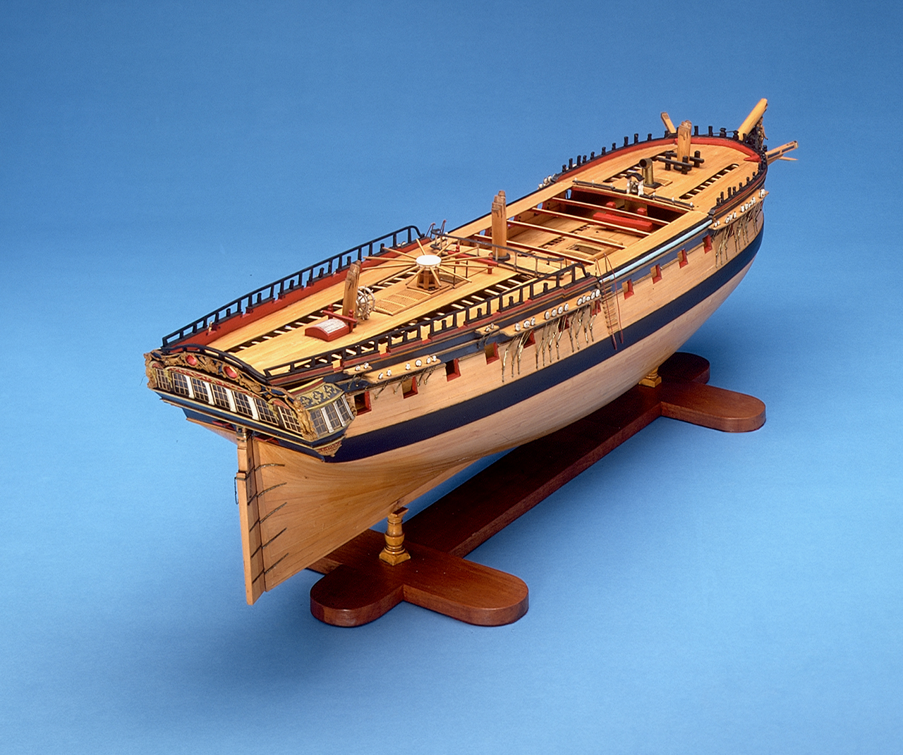
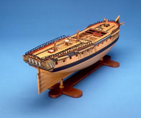
Sjors, I would also have placed it looking forward, but...wanting to make you feel better here is a contemporary model with the chimney facing aft as you have it, I think you can sleep soundly!
- 1,616 replies
-
- 8
-
-
- caldercraft
- agamemnon
- (and 1 more)
-
Looking good. As Mike says, good practice and an opportunity to figure out how you want to finish the more visible decks. Something to remember is that the but shift would only have been used on full planking runs from stem to stern. Planking between any hatch coamings, partners etc would have just used a single plank with no butt joint - visually that means the butt shift is less apparent along the center line.
-
Thats looking sweet Eamonn! Curious what influenced you to put the angle brackets on the coamings next the holes for the anchor hawse? Never seen that before but looks great. Is it paper?
- 1,039 replies
-
- 1
-
-
- ballahoo
- caldercraft
- (and 2 more)
-
Stern is looking great, very neat decking as well. Well done!