Old Collingwood Posted July 5, 2023 Share #31 Posted July 5, 2023 Excellent work. OC. FriedClams, Egilman, Canute and 2 others 5 Quote Current builds 28mm Battle of Waterloo attack on La Haye Saint Diorama. 1/700 HMS Hood Flyhawk with PE, Resin and Wood Decking. Completed works. Dragon 1/700 HMS Edinburgh type 42 batch 3 Destroyer plastic. HMS Warspite Academy 1/350 plastic kit and wem parts. HMS Trafalgar Airfix 1/350 submarine plastic. Black Pearl 1/72 Revell with pirate crew. Revell 1/48 Mosquito B IV Eduard 1/48 Spitfire IX ICM 1/48 Seafire Mk.III Special Conversion 1/48 Kinetic Sea Harrier FRS1 Link to comment Share on other sites More sharing options...
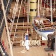
xodar461 Posted August 9, 2023 Author Share #32 Posted August 9, 2023 (edited) Greetings! On to the Jewel. When I bought Foss landing, there was an option to purchase 2 waterline boats to go with the Foss diorama, the Jewel and the Addison. Up first is the Jewel. The waterline molded boat is pretty good with regard to detail. I first used a white primer for the base layer. Below the lower wale was painted red, above left white. The decks were painted off white. here is a photo at this stage: The deckhouse is built using a template with the boards weathered and painted as described previously, then glued directly onto the paper template. This next photo shows the process with the portholes supplied. They were a variety of colors with a gloss finish. 3 are in their original state, 3 have been "roughed up" and painted grimy black. This next one is the aft wall before painting, and the portholes with "rust." Portholes now installed. I painted the roof a speckled white like the walls and then realized that it should have been black. Easy enough to fix and it can be seen on later photos. The walls were then glued to the appropriate place on the boat. Rather than try to glue the whole thing at once, I first glued just the forward wall with epoxy. When that set, I bent the walls around the former on the deck to achieve the final structure. Because the walls are pretty flimsy, some wood was added to the perimeter at the top to give more gluing area for the roof. The front window is installed around this step too. Instructions call for the plastic to be fogged using DioSol, however, I decided to go with a clearer window as I could not imaging running a boat with windows that were too foggy. The rear wall is then glued on when complete. I thought the deckhouse looked too empty, especially with the clear "glass" in place. So, prior to putting the roof on, I decided to try to make a ships wheel using some spare ship modelling parts. The rings are small mast hoops; wood strips cut from 0.5 x 5 mm strip to 0.5 x 1 mm. The central hub is a rough 3 mm circle of styrene. Here is the result. Looks ok, considering it will be inside the deckhouse. I made one for the Addison as well. And here's what it looks like inside the deckhouse. Once the roof is installed, the horn, some sort of ?smokestack and ?vent are installed. Weathering and rust applied to ship. The hardware for the rigging has been installed as well. This includes several eyebolts, 4 cleats and door / hatch handles. Unfortunately, I somehow lost the cleats that came with the kit. Luckily, I had some spares from a prior model that were close enough in size, so I used 2 of these that were slightly larger aft, and 2 from the Addison will be used forward. I also used smaller eyebolts as I felt the ones in the kit were a bit too large for the HO scale (full size would translate to a 10-inch eyebolt). And finally, the name was changed to "Golden Jewel." When researching ships of this size, the name is often on some sort of wooden or metal plaque attached to the hull. I reduced and printed a very small name and glued it to a thin wood strip, then glued this to the hull. Next post will be the rigging. Jeff Edited August 9, 2023 by xodar461 mtaylor, JacquesCousteau, Egilman and 14 others 17 Quote Link to comment Share on other sites More sharing options...
gjdale Posted August 9, 2023 Share #33 Posted August 9, 2023 Very nicely done Jeff. Canute, FriedClams, Jack12477 and 3 others 6 Quote Grant ____________________________________________________ Current builds: African Queen - Radio Control / Live Steam Previous builds: The Shipyard at Foss' Landing (Diorama), Hannah - Ship in a Bottle, NRG Capstan Project, 1869 Allerton Steam Pumper, Medway Longboat , Alfa Romeo Spider Gran Touring (Pocher) , Da Vinci Flying Machine, 1949 Chris Craft 19' Racing Runabout - Dumas - Radio, Bomb Vessel Granado, 1742 - Cross Section - Scratchbuild, HMS Victory (Mamoli 1:90), Cutty Sark, Armed Pinnace, Bounty, Santa Maria At another place: Stephenson's Rocket (OcCre 1:24) (click the title to follow the link) In the Gallery: Lancia Armata 1803, Bomb Vessel Granada, 1742 Cross Section, 1949 Chris Craft 19' Racing Runabout Link to comment Share on other sites More sharing options...
yvesvidal Posted August 10, 2023 Share #34 Posted August 10, 2023 Very nice boat. So realistic even at that scale. Yves mtaylor, FriedClams, Old Collingwood and 2 others 5 Quote Link to comment Share on other sites More sharing options...
xodar461 Posted August 11, 2023 Author Share #35 Posted August 11, 2023 Greetings! Thanks for the kind comments. Here are some photos of my rigging for the Jewel. While the basic layout is similar to the kit plans, I used ropes from my ship modelling (Syren) rather than those supplied. I did not want to tie the ropes directly to the eyebolts (exception here is the rope leading from the mast to the bow. Rather, I wanted to use turnbuckles. In researching similar such ships, I found that this was a reasonable way to attach the ropes. I tried making them from a small wooden dowel but was not feasible given the small scale. Luckily, I found a place online to get them. A small eyebolt was threaded through the central opening to give the final result. The kit supplied eyebolts can also be seen in the above photo. The kit had a unique way to simulate blocks, but as in the ship under repair (see a few posts earlier), I decided to use real blocks and rigging that seemed to make sense after looking at fishing vessels online. Final touch included a bunched-up fishing net at the stern (leftover hammock netting from a prior build). Here are a few photos to show the results. And to finish it off, a small bird can be seen landing on the mast. And one final item. I found an online Canadian company that has many unique HO scale mini kits. Some were pretty cool and I could not resist. Here is one example, an old- time cigarette machine, placed under the steps of the Clam and Oyster building. I'll show some of the other items as I complete them. Next up is the Addison. Jeff mtaylor, NavyShooter, Baker and 10 others 12 1 Quote Link to comment Share on other sites More sharing options...
Canute Posted August 11, 2023 Share #36 Posted August 11, 2023 Do you have the URL for that Canadian company? That's a fine looking cigarette machine. 😃 Old Collingwood, mtaylor, Egilman and 1 other 4 Quote Ken Started: MS Bounty Longboat, On Hold: Heinkel USS Choctaw paper Down the road: Shipyard HMC Alert 1/96 paper, Mamoli Constitution Cross, MS USN Picket Boat #1 Scratchbuild: Echo Cross Section Member Nautical Research Guild Link to comment Share on other sites More sharing options...
king derelict Posted August 11, 2023 Share #37 Posted August 11, 2023 The Jewel came out really well. The rigging is very nice and the bird is a great touch Alan Egilman, mtaylor, Old Collingwood and 1 other 4 Quote Link to comment Share on other sites More sharing options...
xodar461 Posted November 9, 2023 Author Share #38 Posted November 9, 2023 (edited) Greetings! It has been a while since my last post but work proceeds on Foss Landing. I have completed the Addison and here are a few photos. Construction is quite similar to the Jewel so there is no need to repeat. As with the Jewel, I chose to rig with scale blocks and rope, using turnbuckles for the standing rigging. The arrows on the photo below were for a brief tutorial on rigging that can be found on the Sierra West forum. I will probably add some more details like netting, spare rope and barrels at a later time. This completes the structures of Foss Landing. Here are some photos of them all laid out like in the diorama. And here is a photo of some HO scale add-ons that can be seen in the photos above. Next up: finishing the barrels, oil drums and trash cans, then onto the Shipyard. Jeff Edited November 9, 2023 by xodar461 NavyShooter, Jolley Roger, Landlubber Mike and 15 others 12 6 Quote Link to comment Share on other sites More sharing options...
ccoyle Posted November 9, 2023 Share #39 Posted November 9, 2023 Love the vending machines -- they bring back memories. Canute, FriedClams and Old Collingwood 3 Quote Chris Coyle Greer, South Carolina When you have to shoot, shoot. Don't talk. - Tuco Current builds: Brigantine Phoenix, Hawker Hurricane Link to comment Share on other sites More sharing options...
xodar461 Posted December 1, 2023 Author Share #40 Posted December 1, 2023 Greetings, Here we are at the last part of Foss Landing, the barrels and oil drums and rowboats. The rowboats will be upside down scattered around the diorama so no need for the interior detail work. I have a few larger HO scale rowboats that will be more complete Below is the small scale. I found a photo of a scale face and shrunk it down (a lot!) and glued it to the front of the scale. This completes the structures and castings of Foss Landing. Constructions will soon start on The Shipyard at Foss Landing. Looking forward to this - a larger, more detailed building. Shout-out to to folks on the Sierra West forum for their wonderful tutorials. Jeff Old Collingwood, mtaylor, Egilman and 9 others 11 1 Quote Link to comment Share on other sites More sharing options...
xodar461 Posted December 27, 2023 Author Share #41 Posted December 27, 2023 Greetings. now on to The Shipyard at Foss Landing. A fellow member, gjdale has created a build log on this kit so I'll not spend time replicating what he has done. His build log is an excellent reference for anyone wishing to tackle this kit. Unlike the Foss landing buildings, the structures of the Shipyard are built up from wood strips. Each strip has to be stained, weathers and glued in place. The Sierra West forum has some great tutorials on how to do this. The strips are then glued to a thick cardboard backing to create the walls Here's a photo of some of the main building wood strips. Chalk (Rembrandt 408.3) and alcohol applied after some texture using a wire brush. I plan to do some of the more advanced wood work as described such as edge sanding, splits, knots. bottom of boards wear and tear, etc.) as I place the boards on the walls. This will also keep things from getting too repetitive. With the initial wood chalked, it's time to start the walls of the main building. Quite a difference in construction compared to Foss Landing. First a little background on how I laid the boards. First consideration - how long should each plank be? A single plank across the full face of the left or right walls would be are 156 mm across, equivalent to 44 ft at full scale - much too long for a single board. With a little research, I found that typical lengths for wood housing planks are 12 ft (HO 42 mm). Longer lengths offered would be 16 ft (56 mm), 20 ft (70 mm), 25 ft (87 mm). Not sure if this would translate to a building such as this but I decided to go with it. I felt that 42 mm was a bit small so the longer lengths were used. Any space on the wall that was at scale 10-12 ft or less would not have any butt joints in my opinion. With this in mind, here is the left wall with the planks laid out but not glued. Per my previous post, full length planks were initially treated with chalk. Once cut to size, they were finished in a manner described using tutorials on the Sierra West forum. Damage to boards such as splits, cracks, etc. were kept to a minimum. To quote the instructions, "this is a working shipyard and repairs would be made quickly..." Below, the boards have been cut to size, weathered and laid out on the wall template. Notice the solitary plank sitting on the scribed area. It has a visible grain that does not take chalk or AI stain very well. Several of the full-length boards have areas such as this so one has to be vigilant that none find their way onto the wall. It was interesting to note that the visibility depends on the orientation of the board as well. So once the boards are laid out, each was marked on the reverse side with a sharpie. The number on dots indicate which row it goes to. For the second floor boards, using my rule from above, no butt joints were added as the length was 38 mm (full scale 10.8 ft). I also added some chips and gouges to a few of these boards, figuring they would end up a bit more weathered than the first floor, but nothing too severe. Final result: Dormers are next. Jeff gjdale, FriedClams, GrandpaPhil and 8 others 11 Quote Link to comment Share on other sites More sharing options...
xodar461 Posted January 8 Author Share #42 Posted January 8 Greetings! Work continues with the dormers. Construction was pretty straight forward. As I've stated before, I won't go into all the details as the log by grant covers this quite well. I did add some beams across the back to add some rigidity to the structure. The flashing on the right wall dormer sides is to be removed, painted then glued back, flush with the back of the wall. To give this delicate piece a larger surface for the glue, I first glued a piece of paper to the back of the side wall then glued the flashing into its space. I also noticed that when the dormers are placed onto the left and rear walls, the lower part of the scribed inner wall is visible. I did not like this look so it was covered with the same planks used for the walls. I think this looks better. BTW, the white of the window frames still looks a bit stark as I have not yet toned them down with some grey chalk. Completing the doors and windows that go on the walls was a breeze thanks to the kit's construction methods. Here is a photo of the freight doors. And before applying the "SHIPYARD" stencil, I did a practice run on some scrap wood. here is the result. And finally, my thoughts on adding nail holes to simulate where the boards are nailed to the underlying beams, which is an option given during construction. I've reading many of the comments on the SW forum, I decided to place small "holes" only where 2 boards butt. In researching what kind of nails are used on wood siding, I came up with a nail size of 8d. This has a nail head size of 9/32 inch. At HO scale, converting to metric, this is ~ 0.08 mm, which is the approximate diameter of a human hair. The smallest nail indent I could make, even with the finest sewing needle, is 0.2-0.3 mm (this translates to a 1 inch nail head). I did some nail holes on the Foss landing building and looking at them now, they are barely visible after the building has been finished, and only from very close up. And if we are looking at the model at a distance of 1 foot, this would translate to 87 feet - how visible would nail holes be at that distance. So with all this in mind, I decided to forgo the nail hole rows. Similar discussions can be found on this forum on the use of treenails on deck and hull planking, especially at scales less than 1:48. after a few more steps the walls will be glued together and the building will begin to take shape. jeff GrandpaPhil, ERS Rich, Canute and 9 others 12 Quote Link to comment Share on other sites More sharing options...
xodar461 Posted January 17 Author Share #43 Posted January 17 (edited) Greetings! Rear wall construction now complete. No significant issues encountered. As noted in Grant's log, the rafters were a bit long when cut out using the template. It was easy enough to fix though. Regarding the signs, the instructions mention that several copies are supplied on a single sheet. I had just one copy on a template sheet. I made a few copies before working on them. Glad I did as the first try was not acceptable. The awnings were a bit delicate - too much bending of the side pieces or the scalloped edges and they would come off. Each one was stiffened with a light coating of white glue after they were bent in place. First photo shows the larger awning placed using 2 wood spacers to ensure it was centered in the correct position (sharp eyes will see that one spacer was turned the wrong way when I took the photo). Next 2 show the finished rear wall. The left wall was much easier as only the dormer, landing and sawdust collector had to be fixed to the wall. Having the pre-drilled holes to locate the correct position of the dormers made this quite easy. Template seen below aided in construction of the landing. One question I have about the sawdust collector (seen below on the right of the wall). I gather that it is a vacuum that collects sawdust from the shop, however, wouldn't there be a hose or tube at the open end (see red circle below photo) that would lead to a barrel or container to collect the sawdust? Otherwise, sawdust would spray all over the place. Unfortunately, I have not been unable to find any similar contraption on the internet. I am thinking of making some sort of tube that would lead down to an oversized barrel. Any thoughts? Next post I will show the stenciled wall and right wall. Jeff Quote Leave a Comment Home • HO Scale Builds Preview Save Draft Edited January 17 by xodar461 FriedClams, gjdale, Canute and 9 others 12 Quote Link to comment Share on other sites More sharing options...
gjdale Posted January 17 Share #44 Posted January 17 Looking good Jeff. I have no idea in answer to your question, but I’m sure the folks over on the SWSM forum will be able to give you some good advice. Jack12477, Canute, mtaylor and 2 others 5 Quote Grant ____________________________________________________ Current builds: African Queen - Radio Control / Live Steam Previous builds: The Shipyard at Foss' Landing (Diorama), Hannah - Ship in a Bottle, NRG Capstan Project, 1869 Allerton Steam Pumper, Medway Longboat , Alfa Romeo Spider Gran Touring (Pocher) , Da Vinci Flying Machine, 1949 Chris Craft 19' Racing Runabout - Dumas - Radio, Bomb Vessel Granado, 1742 - Cross Section - Scratchbuild, HMS Victory (Mamoli 1:90), Cutty Sark, Armed Pinnace, Bounty, Santa Maria At another place: Stephenson's Rocket (OcCre 1:24) (click the title to follow the link) In the Gallery: Lancia Armata 1803, Bomb Vessel Granada, 1742 Cross Section, 1949 Chris Craft 19' Racing Runabout Link to comment Share on other sites More sharing options...
xodar461 Posted January 23 Author Share #45 Posted January 23 Greetings! Right wall and front stenciled wall now complete. I was not entirely happy with the cardboard awning supplied with the kit, so I decided to replace it with a wooden one using boards from prior ship models. I used the cardboard awning as a template to mark the tar paper lines on the new awning (pencil lines can be seen on the top photo). Marking for the supports and the middle were also marked. One side was stained, the other will be tarped. Final wall: Here is the front wall with the Shipyard stencil. Gluing the walls together is next. The rear and side wall were glued together first, using a metal right angle to keep things lined up. I then glued on the front wall, using graph paper to line up the walls as well as the supplied internal cardboard supports and several square beams (each beam was the same length measured to .01 mm). This makes the structure quite solid. Note in the second photo the missing awning on the rear wall, knocked off during the gluing process. It was easy enough to repair but illustrates how delicate some areas are. I have decided to add some lighting to the diorama. I plan to put some LEDs in all the main buildings of both Foss Landing and the Shipyard, pendant LEDs in the saw shed, goose neck lights over some of the doors and hopefully some streetlights. I even found some small LEDs to simulate a fire in an open oil drum! So, while waiting for the LEDs to arrive for the main building, I decided to build a billboard for the flat roof of the Foss Landing Launch Co. not sure what sign I will put on the billboard but here's what I came up with using some ideas I found online. Jeff Canute, FriedClams, Old Collingwood and 9 others 11 1 Quote Link to comment Share on other sites More sharing options...
xodar461 Posted February 6 Author Share #46 Posted February 6 (edited) Greetings! It's time for the roof and shingles. A long beam is first glued between the end walls to give the cardboard base some support. I decided to add some vertical beams for additional support. Once the roof is glued in place and some strips are added to roof ends, it time to begin with the shingles. But first, the dormers are glued in place. As the first 11 rows are broken up by the dormers, it was important to correctly place the shingles between the dormers so that when full length strips are placed beginning row 12, the offset from row to row will be consistent. I first placed 3 rows on the left, then placed a full length on row 5. Rows 1,3,5 will have full width shingles on the end. The pencil line (blue circle) marks the edge of a shingle that was used to line up row one. The same process was used to line up row one on right side of the roof. I may have been overthinking this but last thing I wanted was to get to full length strips and have the shingles misaligned. After row 3, the dormer roofs are added, then flashing added to dormer - roof interface and then more shingles. Grant's log has some nice photos of this process so I won't repeat here. Here are some photos of the progress. A small triangle has to be cut out of the shingle strip on row 12 to accommodate the peak of the dormer roof. This took a few tries to get it right (one loose strip can be seen in the photo above. After row 12, it was pretty straight forward up to the cupola. As 2 strips were a bit too short to cover the length of the roof, filler pieces had to be used. To keep the offset consistent, on occasion a very slight amount had to be removed from an end shingle here and there. Once up to the cupola, shingling was paused to construct the cupola. The walls are lined with strip-wood, window frames painted and placed, and the wall glued together. Trim is added to the base to accommodate the black paper flashing. The instructions called for the trim at the base to be a 0.02 in strip (0.5 mm). I felt this was a bit small to run the flashing onto the trim, so I doubled it to 1mm. The cupola is then glued to the roof and shingling completed. The cupola roof is completed in much the same way as the other roofs. The same process was used for the other side. Here is the completed roof of on the side with the dormers. Once the roof is complete, rafters are added - full length at the ends of the main and dormer roofs, extensions elsewhere. Here is the roof complete. I decided to paint and place the chimney at this stage as I was eager to see how it looked. I may do some weathering of the roof below the chimney to represent soot. Also, the capping shingles used were cut from the paper border of the shingle sheet, ~4.4 mm in width. Instructions called for using single shingles for this process but I though they looked too small. Here's a photo with both for comparison. And lastly, before the roof was placed, LEDs were placed, one each in the large dormers,, 2 in the main building and a swan neck over one of the freight doors. The dirty windows and shades limit views of the inside. On deck, the warehouse building. Jeff Home • HO Scale Builds Edit Save Draft Edited February 6 by xodar461 mtaylor, Canute, JacquesCousteau and 11 others 12 2 Quote Link to comment Share on other sites More sharing options...
Old Collingwood Posted February 6 Share #47 Posted February 6 Excellent work. OC. Canute, Egilman and mtaylor 3 Quote Current builds 28mm Battle of Waterloo attack on La Haye Saint Diorama. 1/700 HMS Hood Flyhawk with PE, Resin and Wood Decking. Completed works. Dragon 1/700 HMS Edinburgh type 42 batch 3 Destroyer plastic. HMS Warspite Academy 1/350 plastic kit and wem parts. HMS Trafalgar Airfix 1/350 submarine plastic. Black Pearl 1/72 Revell with pirate crew. Revell 1/48 Mosquito B IV Eduard 1/48 Spitfire IX ICM 1/48 Seafire Mk.III Special Conversion 1/48 Kinetic Sea Harrier FRS1 Link to comment Share on other sites More sharing options...
xodar461 Posted February 27 Author Share #48 Posted February 27 Greetings! Work continues on the main building. The attached warehouse is complete. Not much extra to add from the instructions though I did add some beams behind the metal doors for some support. See photo below, upper right. I had to salvage some scraps from the wood pile to complete the walls. Here is the competed wall and doors. The roof goes on much like the awnings on the main building. Here are some photos of the warehouse attached to the main structure. One LED was added to the interior of this section. Excuse the simulated bird poop on the warehouse roof! The Yardmaster office is next. The clapboard siding was fun to build and if you look closely, there are boards that are split, chipped and a few that have part of the board missing. Roof is almost complete in these photos. The office will have one gooseneck light on the gabled side and one LED inside. Once glued to the main structure, it's onto the items located on the roof. Jeff Old Collingwood, Canute, Landlubber Mike and 8 others 10 1 Quote Link to comment Share on other sites More sharing options...
Canute Posted February 29 Share #49 Posted February 29 Nice work on your roofs, Jeff. FriedClams, Jack12477, ERS Rich and 3 others 6 Quote Ken Started: MS Bounty Longboat, On Hold: Heinkel USS Choctaw paper Down the road: Shipyard HMC Alert 1/96 paper, Mamoli Constitution Cross, MS USN Picket Boat #1 Scratchbuild: Echo Cross Section Member Nautical Research Guild Link to comment Share on other sites More sharing options...
ERS Rich Posted February 29 Share #50 Posted February 29 Enjoying this, thanks for posting. Jack12477, FriedClams, Old Collingwood and 3 others 6 Quote Build Logs: USS Maine, USS Constitution (Hull) Albums: Baltimore Clipper, Sherbourne Cutter, Lackawanna Tug, Eagle Coastal Schooner, Katy Pilot Boat, Sultana Colonial Schooner, Armed Virginia Sloop Link to comment Share on other sites More sharing options...
xodar461 Posted March 6 Author Share #51 Posted March 6 Greetings! The office has been attached to the main building and the pitch and pine tar tank and platform were completed and glued to the warehouse roof. A small hole was drilled in the roof top accommodate the pipe. Here is the structure thus far. First, a few close ups of the tank and platform... ...and the main building. Several stacks are being prepared to glue onto the roofs. Then onward. Jeff Jack12477, Old Collingwood, mtaylor and 8 others 7 4 Quote Link to comment Share on other sites More sharing options...
ERS Rich Posted March 6 Share #52 Posted March 6 On 1/8/2024 at 5:00 PM, xodar461 said: - how visible would nail holes be at that distance Thanks for mentioning this, given how long it takes to build a ship model, one wonders how much time is taken up with “invisible” things such this, or other trivial details pursued for the sake of “realism”, especially by newcomers. Time which could be spent completing the project and gaining satisfaction from that. mtaylor, Canute, Old Collingwood and 1 other 4 Quote Build Logs: USS Maine, USS Constitution (Hull) Albums: Baltimore Clipper, Sherbourne Cutter, Lackawanna Tug, Eagle Coastal Schooner, Katy Pilot Boat, Sultana Colonial Schooner, Armed Virginia Sloop Link to comment Share on other sites More sharing options...
wefalck Posted March 7 Share #53 Posted March 7 Well, 'invisibility' is a matter of viewing distance. It's the conundrum of us modellers that we have to cater for different viewing distances, unless we can force the viewing distance by building a true 'diorama' (in which case also the viewing angle is fixed) or by putting the model/scenic arrangement into a glass-case which gives a minimum viewing distance. My 'rule' is that I try to represent everything that can be physically represented within the limits of materials and tools (and my own dexterity). As one series of travel-guides put it: "you only see, what you know" - of course, if you don't know anything about ships and how they were constructed/operated, you would not miss details, but if you know that is was there, you will miss the detail and if it is only a trivial detail, such as nail or dowel patterns. BTW, I really like this ramshackle and improvised appearance of those buildings. I alwways found it strange, that in the USA there is so much more photographic evidence of such buildings compared to Europe. Perhaps photography was much more frequently practiced in those early years of its development in the USA then in Europe. Or our numerous wars have wiped out such buildings and necessitated rebuilding. Or we tended to build more in stone than in wood. Canute, Old Collingwood, mtaylor and 1 other 4 Quote wefalck panta rhei - Everything is in flux Link to comment Share on other sites More sharing options...
mtaylor Posted March 9 Share #54 Posted March 9 On 3/7/2024 at 12:44 AM, wefalck said: BTW, I really like this ramshackle and improvised appearance of those buildings. I alwways found it strange, that in the USA there is so much more photographic evidence of such buildings compared to Europe. Perhaps photography was much more frequently practiced in those early years of its development in the USA then in Europe. Or our numerous wars have wiped out such buildings and necessitated rebuilding. Or we tended to build more in stone than in wood. I'd think it's a mix of things but yes, the wars had a huge impact as well as building from stone. Jack12477, Egilman, Canute and 1 other 4 Quote Mark "The shipwright is slow, but the wood is patient." - me Current Build: Past Builds: La Belle Poule 1765 - French Frigate from ANCRE plans - ON HOLD Triton Cross-Section NRG Hallf Hull Planking Kit HMS Sphinx 1775 - Vanguard Models - 1:64 Non-Ship Model: On hold, maybe forever: CH-53 Sikorsky - 1:48 - Revell - Completed Licorne - 1755 from Hahn Plans (Scratch) Version 2.0 (Abandoned) Link to comment Share on other sites More sharing options...
xodar461 Posted March 20 Author Share #55 Posted March 20 (edited) Greetings! Work continues with the docks. Template C has the right, left and derrick docks and the sales porch, all done simultaneously. Here is some early progress. The completed docks below. Instructions are very clear cut. Fine ballast was used to create the barnacles on the supports that will be underwater. One variation from the instructions - I decided to paint the skirting speckled white. I found that on many porches, this part was white. I'll probably make the railing white to match. This will be similar to the stairs and railing of Foss Landing. Note that on the derrick dock, I made the height of the "barnacles" less as the dock went inland as the water level would be lower. Now onto the main dock. Here is some preliminary work. I have a question for the any RR enthusiasts out there (not sure there are many here at MSW) - for the rails that are on the dock, where should I terminate the deck planking - at the blue line or red one? I can't seem to find many photos of this online and the pic in other build logs are too low resolution. As always, thanks for the kind comments and thanks in advance for any help on my questions. Jeff Edited March 20 by xodar461 fixed photos Old Collingwood, Jack12477, Egilman and 2 others 5 Quote Link to comment Share on other sites More sharing options...
Canute Posted March 20 Share #56 Posted March 20 Leave the base of the rail as is. If you took it off a real rail, the rail could roll out from under the railcar wheel. Egilman, Old Collingwood, FriedClams and 2 others 5 Quote Ken Started: MS Bounty Longboat, On Hold: Heinkel USS Choctaw paper Down the road: Shipyard HMC Alert 1/96 paper, Mamoli Constitution Cross, MS USN Picket Boat #1 Scratchbuild: Echo Cross Section Member Nautical Research Guild Link to comment Share on other sites More sharing options...
wefalck Posted March 20 Share #57 Posted March 20 (edited) I am not a railway buff, however the inner planking should go up to roughly the blue line, because there needs to be clearance for the wheel-flanges - that is, when the rail does not protrude above the level of the planking. BTW, the link to the pictures doesn't seem to be working or is missing. I had to manually plug the URL into the browser. Edited March 20 by wefalck FriedClams, Jack12477, mtaylor and 3 others 6 Quote wefalck panta rhei - Everything is in flux Link to comment Share on other sites More sharing options...
xodar461 Posted March 20 Author Share #58 Posted March 20 Thanks for the replies. Welfack, when I copied and pasted the post from the Sierra West Forum, initially the URL was seen and not the photos. I think you got to the post before I edited it as now the photos are visible. As far as where the planking ends at the rail, if it stops at the edge of the rail, then I would assume that you would then need spikes to hold the track down like you would have with RR ties. None of the build logs on the SW forum mention this. Re: comment by Canute, I was not implying to remove any of the rail base, but rather should the wood planking cover the flange part of the base up to the rail itself. The multiple planks would server to keep the rail anchored and obviate the need for spikes. I am not sure the wheel flanges would go low enough the hit the wood. I have a rail flatcar that will be part of the diorama so I may test this out. Jeff Jack12477, FriedClams, mtaylor and 3 others 6 Quote Link to comment Share on other sites More sharing options...
wefalck Posted March 20 Share #59 Posted March 20 I am not sure that I understand you correctly re. the planking. I assumed that the planking serves to fill the space between the rails and around them in order to obtain a flat surface without obstacles - as you would when paving around rails. I gather you would need sleepers or other structural elements to keep the rails together. They could be, of course, part of the wooden landing stage. BTW, this growth on the piles looks good, but it wouldn't be barnacles, but rather mussels. Barnacles are only around 1/2" in diameter and sit flat on solid surfaces. FriedClams, Old Collingwood, Canute and 3 others 6 Quote wefalck panta rhei - Everything is in flux Link to comment Share on other sites More sharing options...
Canute Posted March 21 Share #60 Posted March 21 I think I get what you're saying. You need to leave a flange-way for the wheel flanges. You may have to fiddle with the thickness of the boards to permit cars to roll out onto your dock. You really only need to fill that in if you're planning to drive vehicles onto your dock. I'd put some kind of wheel stop on the end of each rail, too. FriedClams, mtaylor, wefalck and 2 others 5 Quote Ken Started: MS Bounty Longboat, On Hold: Heinkel USS Choctaw paper Down the road: Shipyard HMC Alert 1/96 paper, Mamoli Constitution Cross, MS USN Picket Boat #1 Scratchbuild: Echo Cross Section Member Nautical Research Guild Link to comment Share on other sites More sharing options...

Recommended Posts
Join the conversation
You can post now and register later. If you have an account, sign in now to post with your account.