
.JPG.ca33079f5815b861e67b9c2cccd37982.JPG)

Blue Ensign
-
Posts
4,286 -
Joined
-
Last visited
Content Type
Profiles
Forums
Gallery
Events
Posts posted by Blue Ensign
-
-
-
Thank you for your kind words Gus,
These boats are quite tricky to assemble, and I agree with Vanguards rating of ‘experienced’.
I don’t think the 36’ barge is currently on sale, but the 32’ version is.
The boats are quite delicate, at least until they are planked. ‘Soft’ hands and a gentle approach is needed to avoid breakages in areas like the stem and stern during the fairing and planking process.
These small boats aren’t the best candidates for a start in ship modelling, but all you have to lose apart from your temper is the cost of the kit. The danger is that frustration and failure may put you off the hobby for life.
Something like the Vanguard Fishing boat range, The Fifie perhaps, is an excellent choice for someone new to ship modelling, with a high chance of a good result and a desire for more.
I wish you well in whatever you decide.
Regards,
B.E.
- Gus M, mtaylor and Ryland Craze
-
 3
3
-
Thanks Jason,
Without redo's you can't advance in model ship building; it's the 'that'll do' approach that blocks improvements in build quality.
I don't always succeed but as I grow older I'm far less forgiving of myself in terms of 'what'll' do.
Cheers,
B.E.
- gjdale, mtaylor, Wintergreen and 1 other
-
4
-
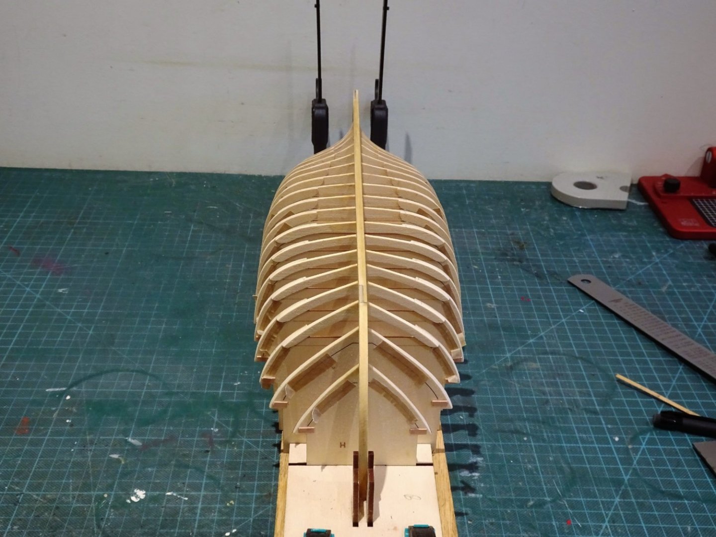
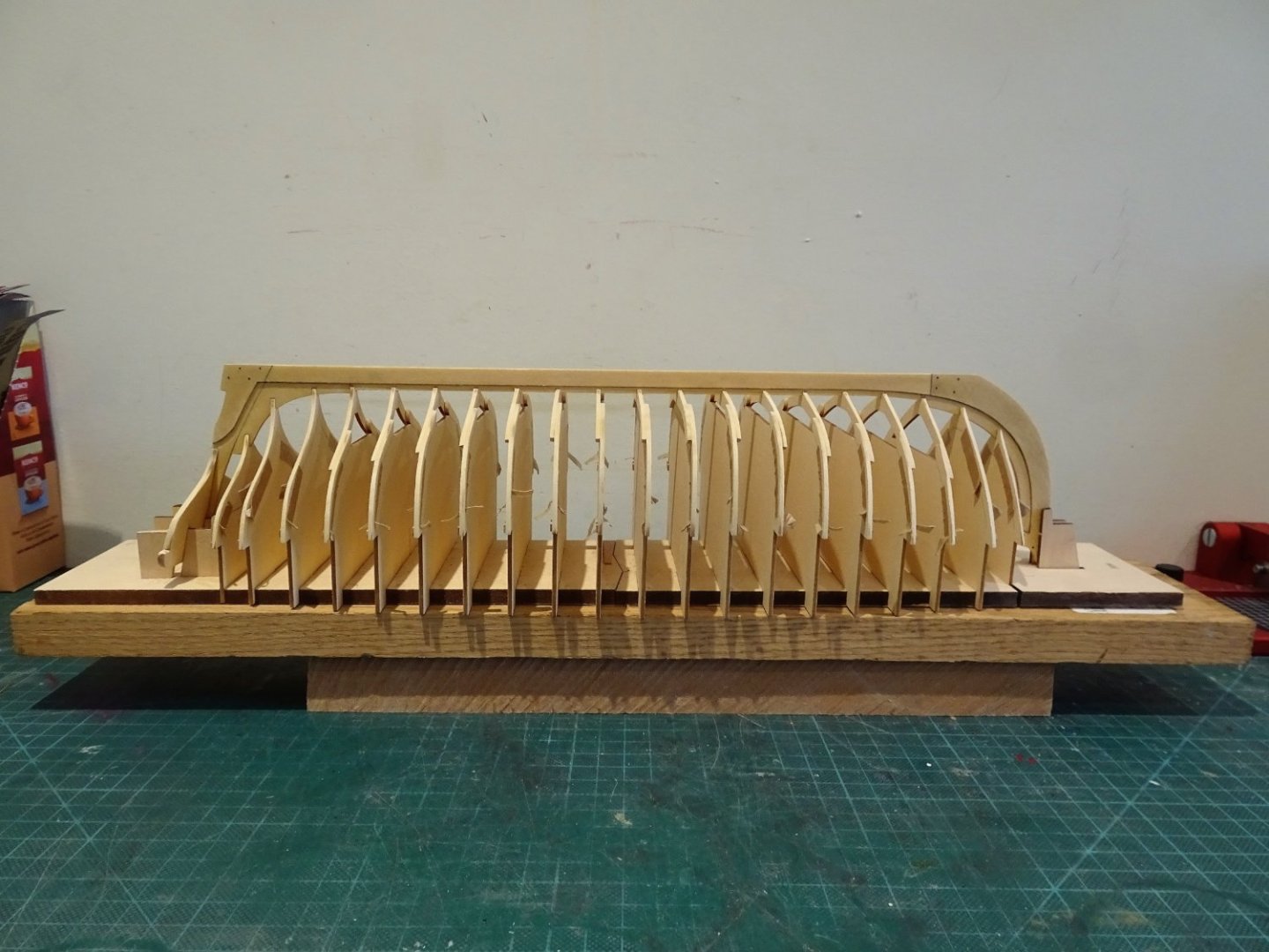
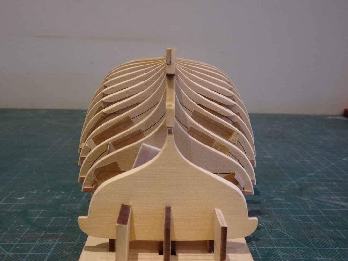
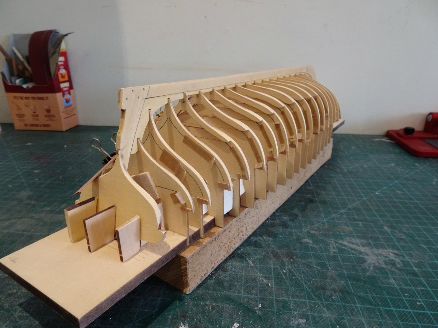
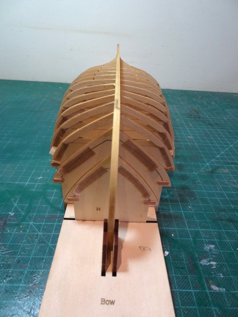
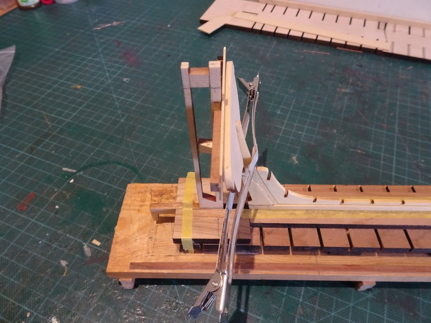
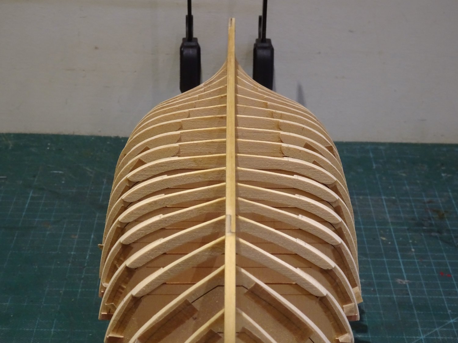
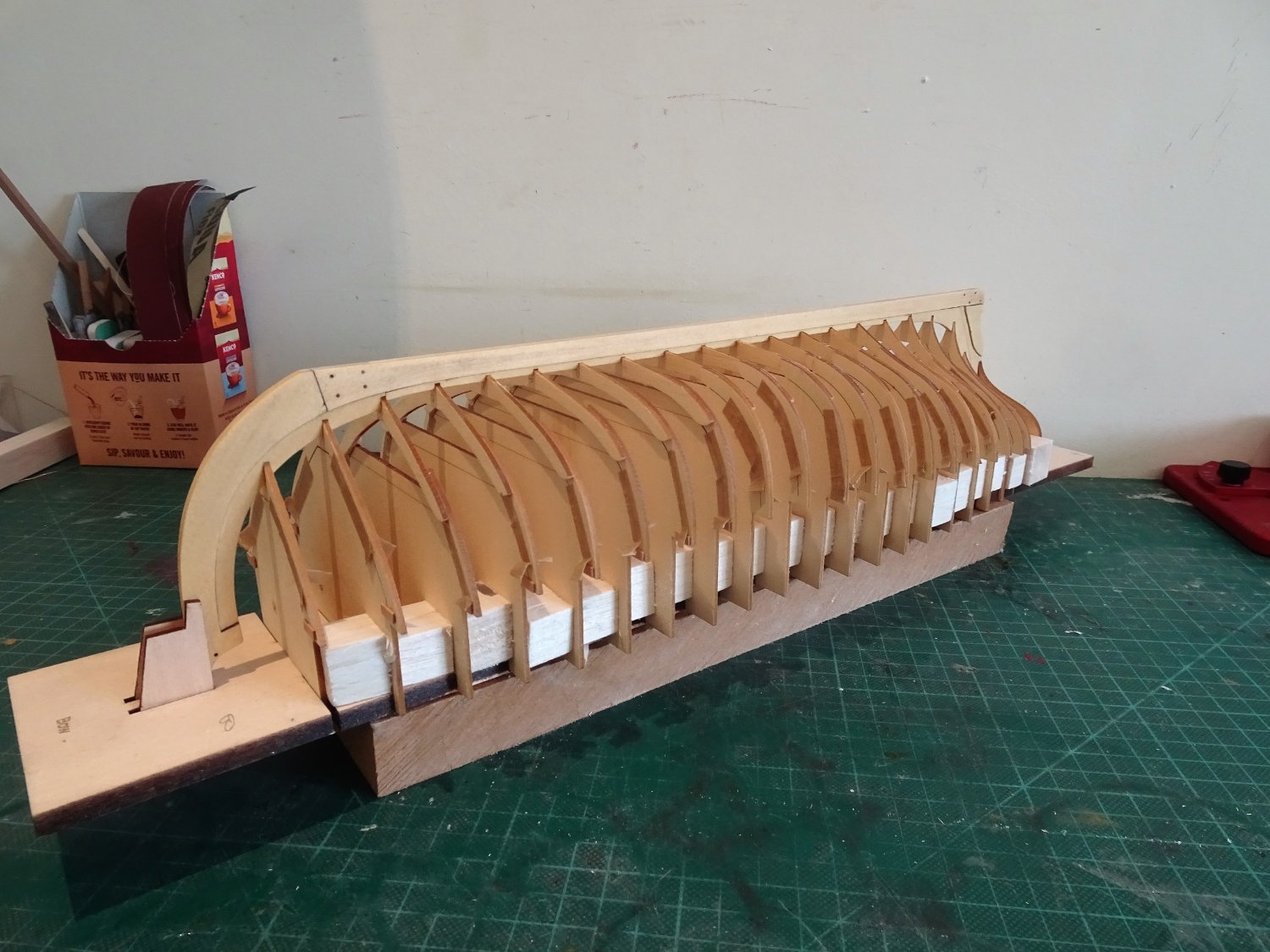
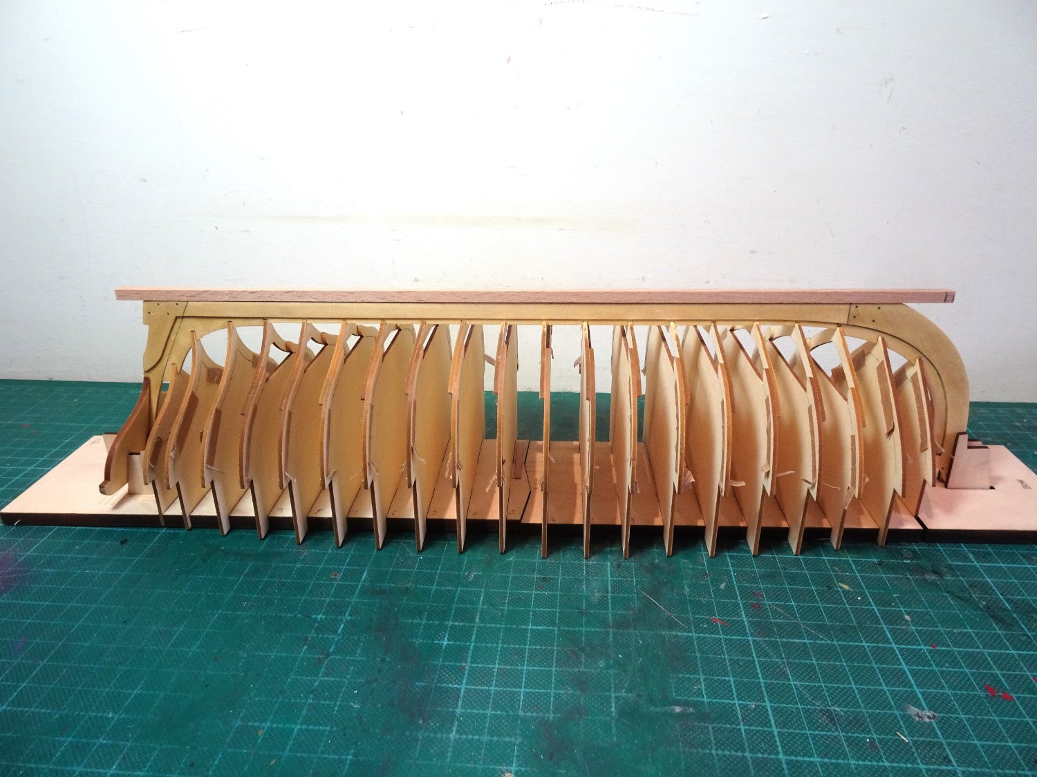
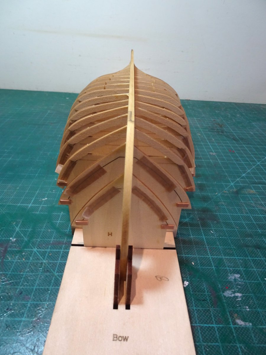
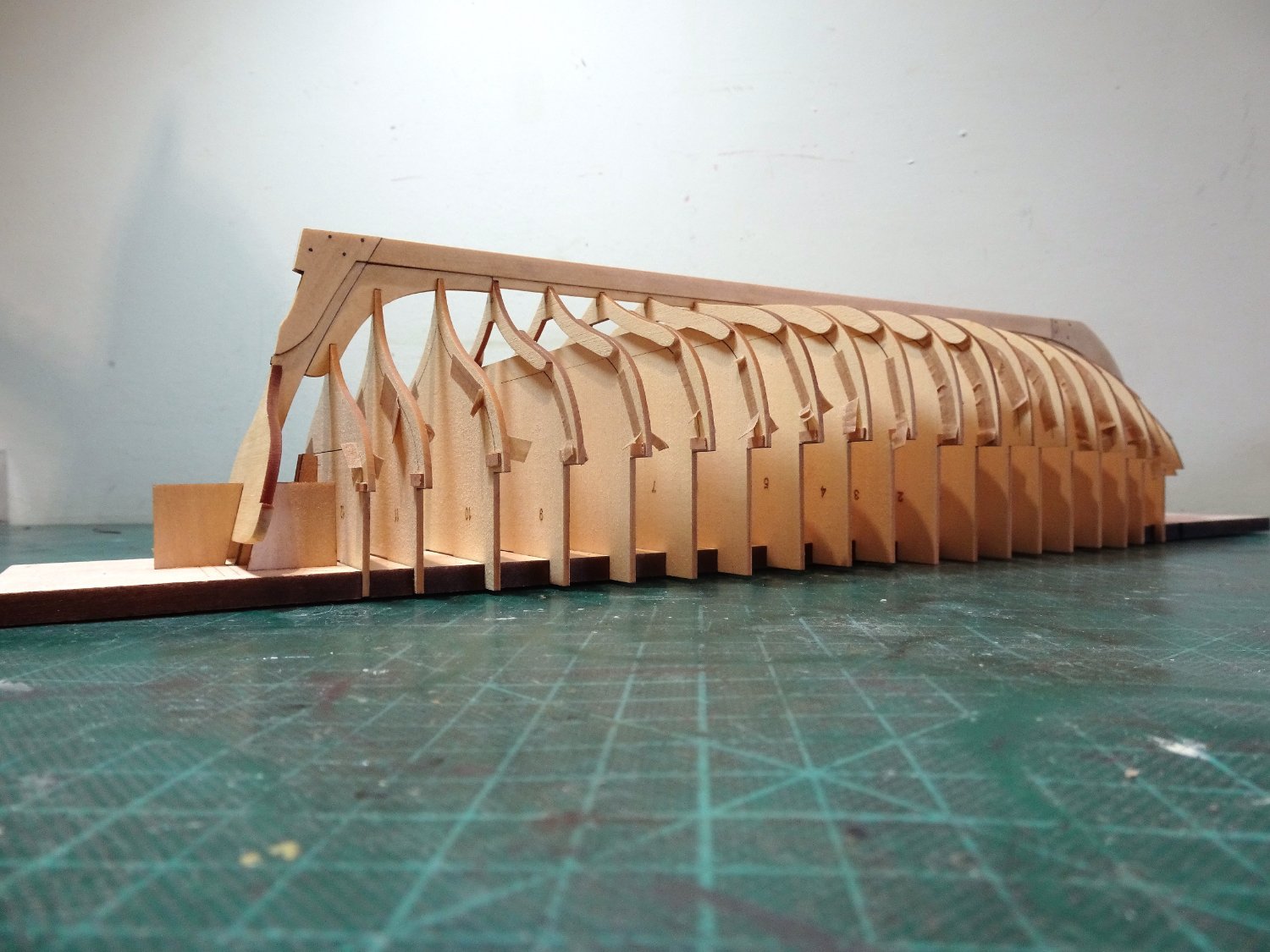
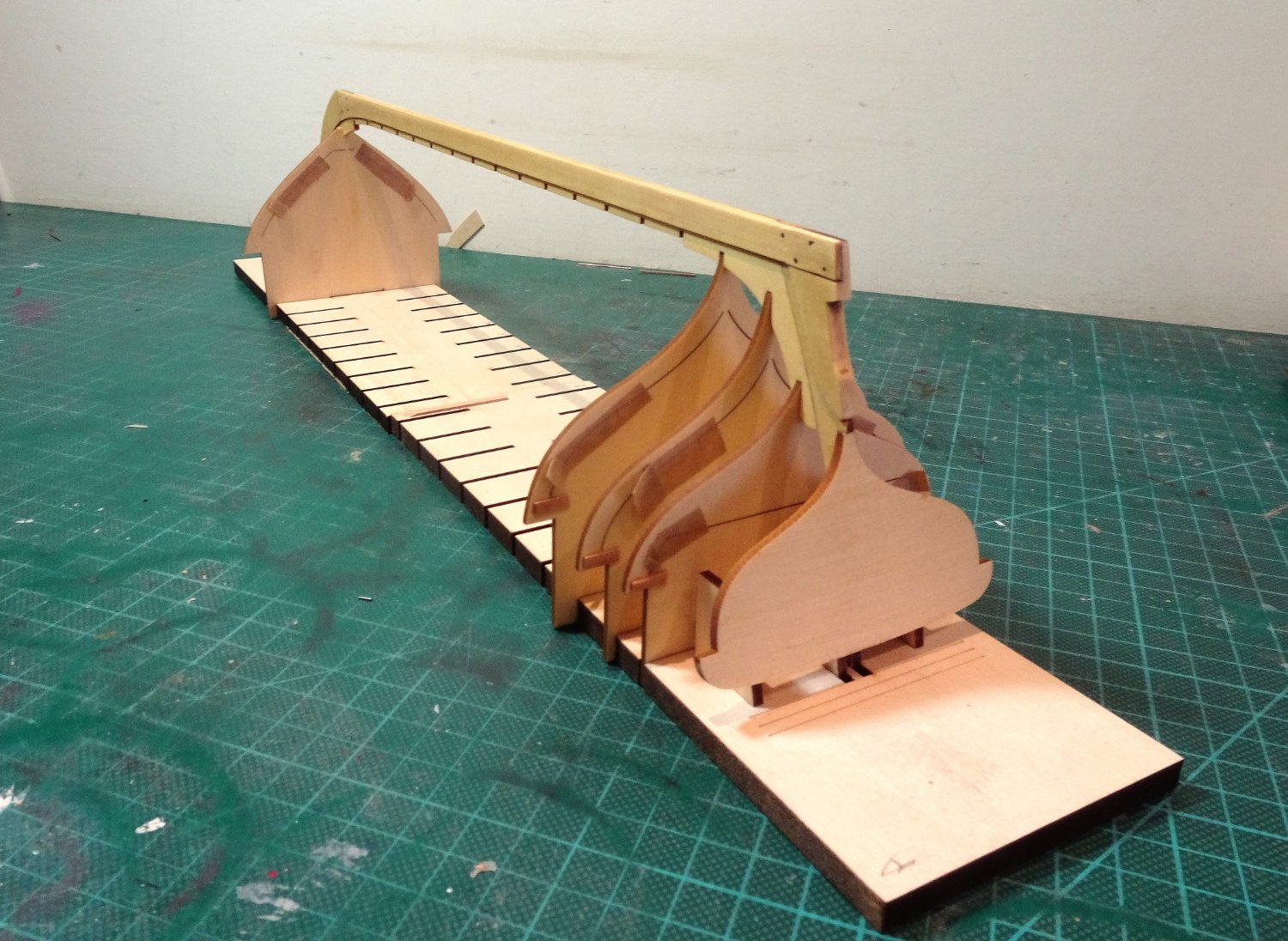
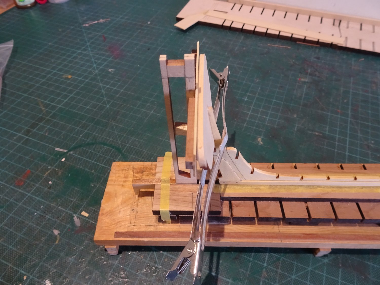
Post Eight.
Armed with Chuck’s good advice and with better heart I sallied forth to re-fix the bow section frames.
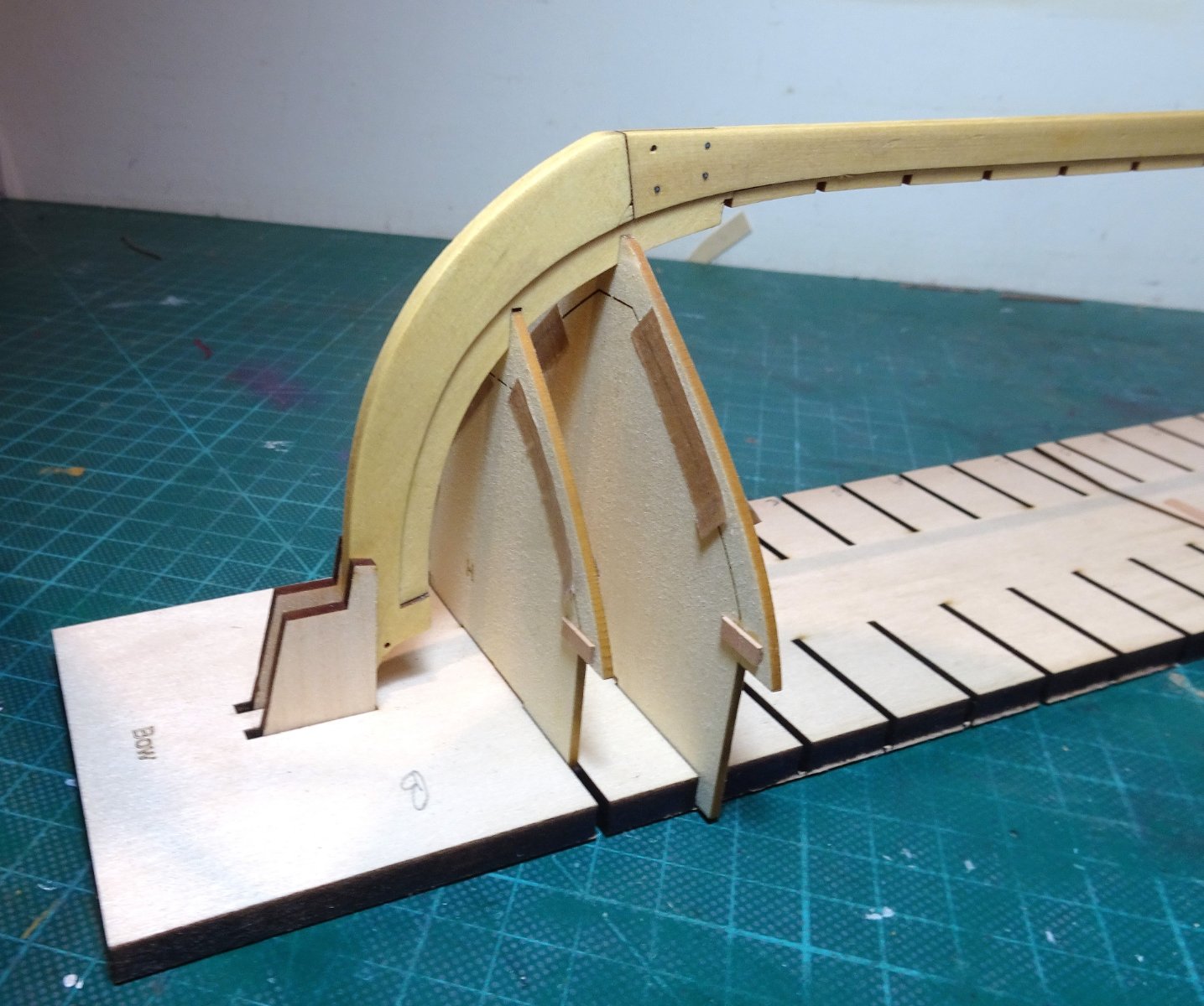
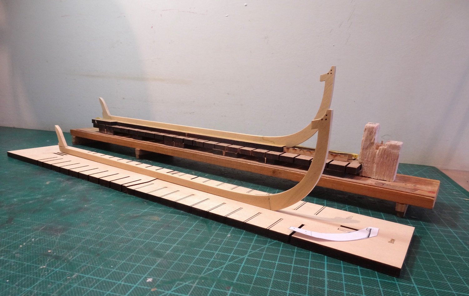
What testy business, once I’d got frames 1 and 2 at the bow spot on centred, attempts to centre the frames along the keel instantly threw them out.
I decided to centre and glue the foremost bow frames H and G into the keel and let them set.
I figured that I could still remove the forward Build board section and then refit it for centring the remainder, noting those which presented difficulty.

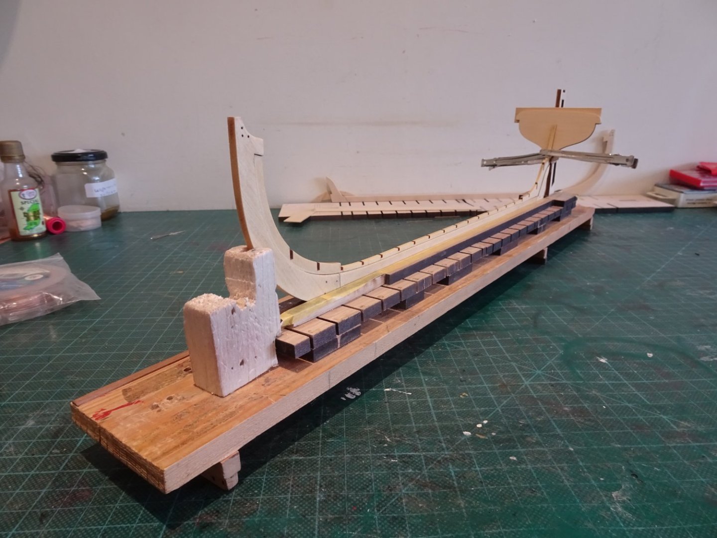
0198
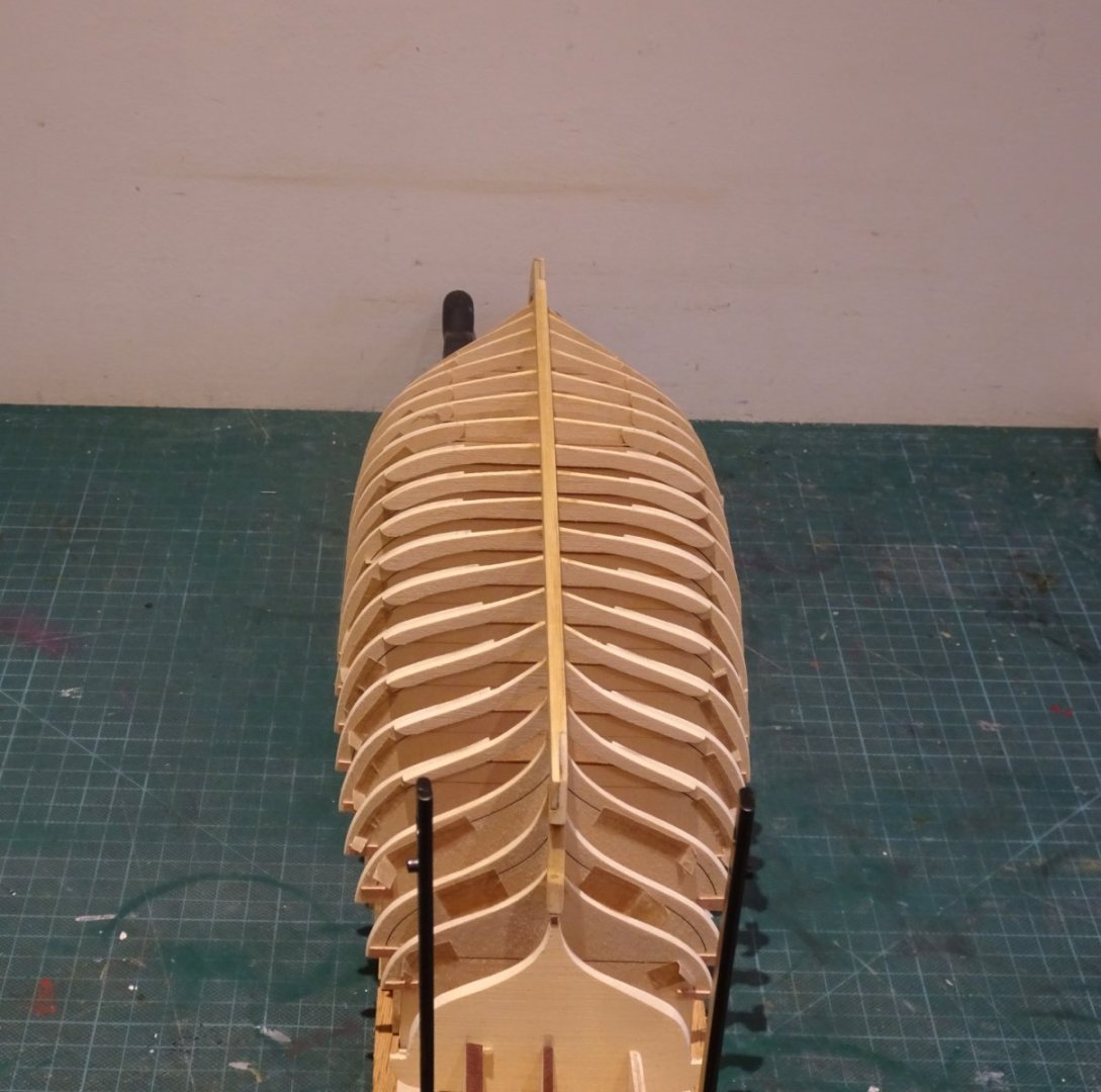
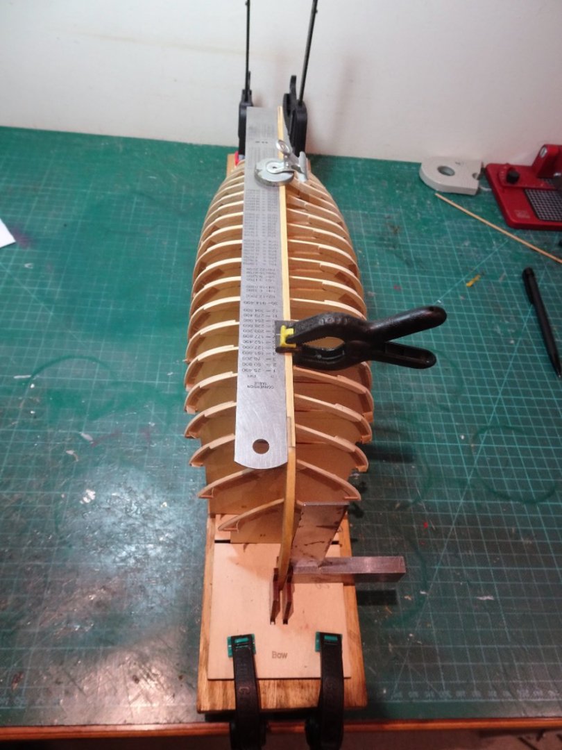
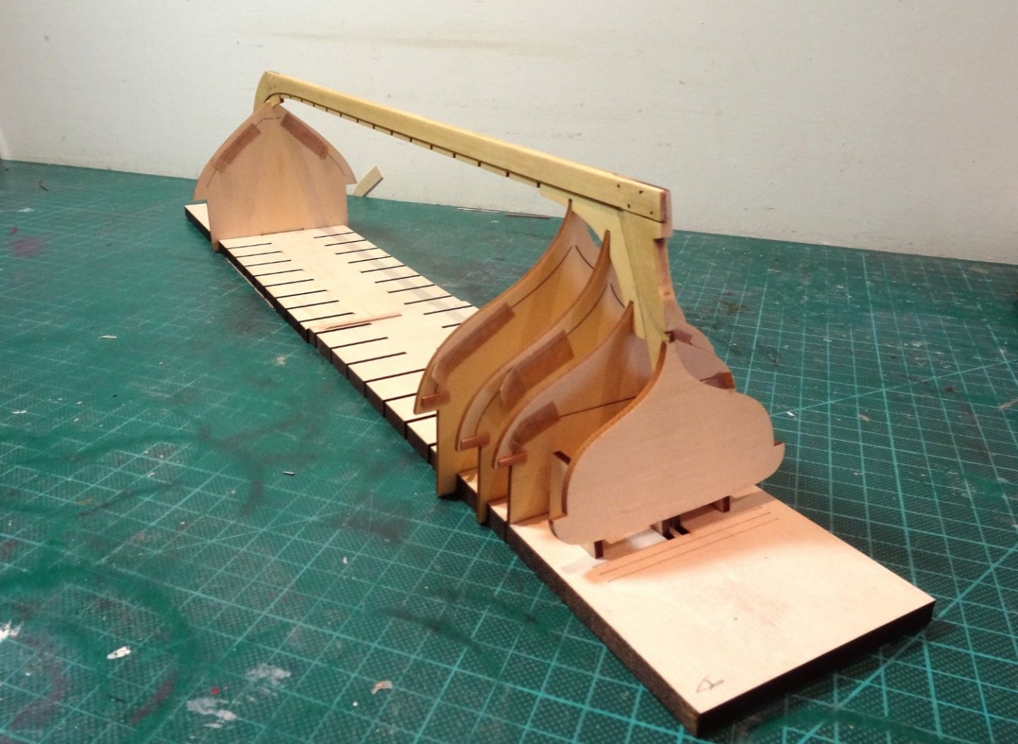
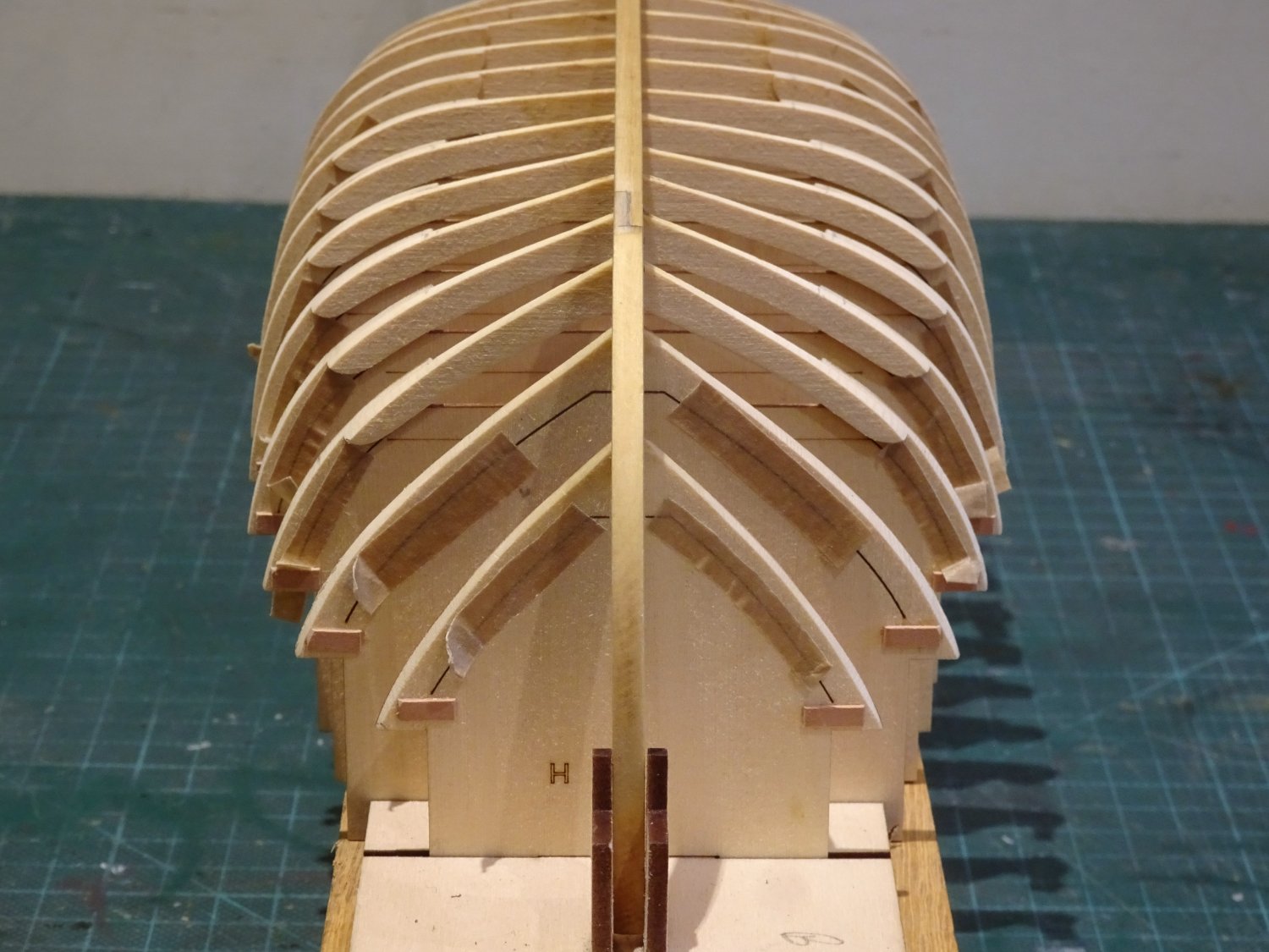
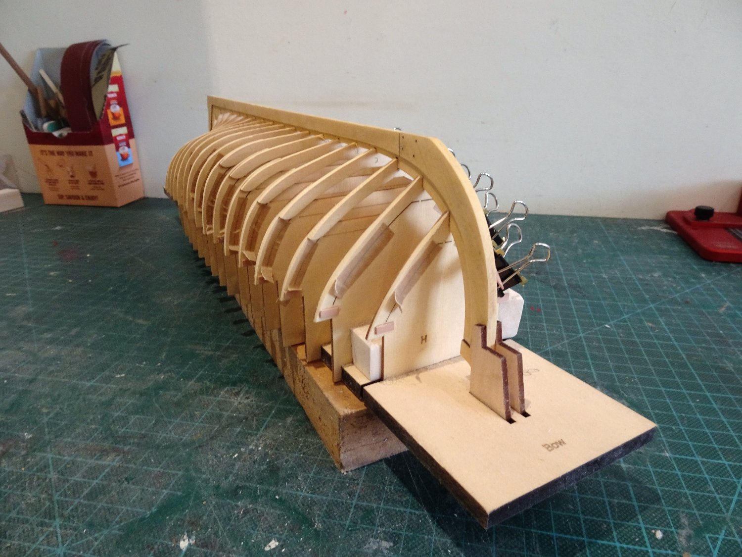
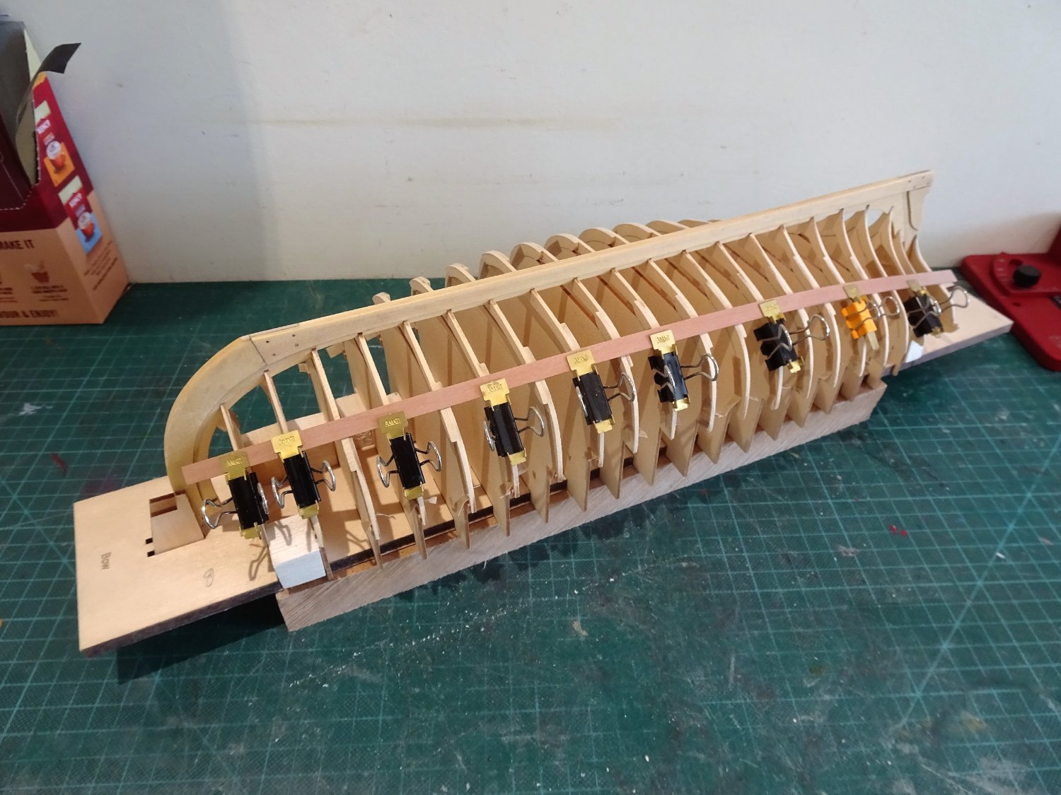
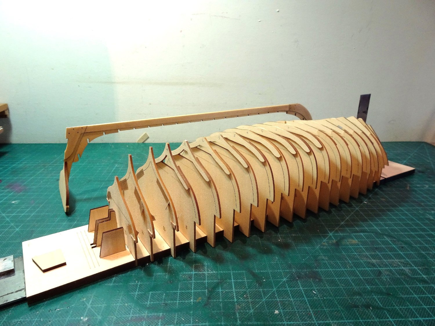
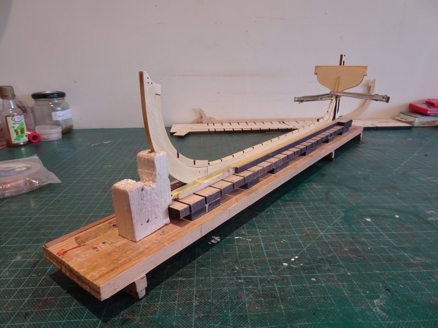
I eased the frames a little to allow the keel notches to slip a little easier across the frames.
It seemed to work, and the remainder were re-fitted and glued.
There was time to check the measurements both sides of the frames which are now matching.

0199
0195
0203A

0206
0204
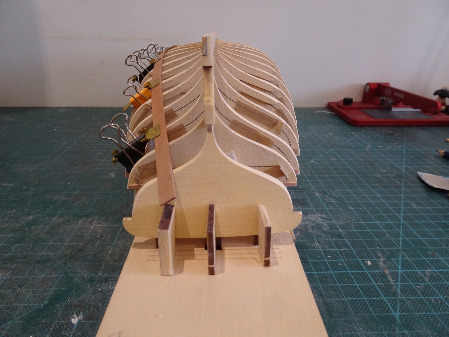
Hopefully back on track, now where did I put those tick strips.
B.E.
03/02/2023
- jpalmer1970, Wintergreen, mtaylor and 8 others
-
11
-
Postscript to previous .
Chuck has identified the likely cause of the issue as the keel not being fully centred on the forward framing section, plus a slight keel bend that I couldn't detect.
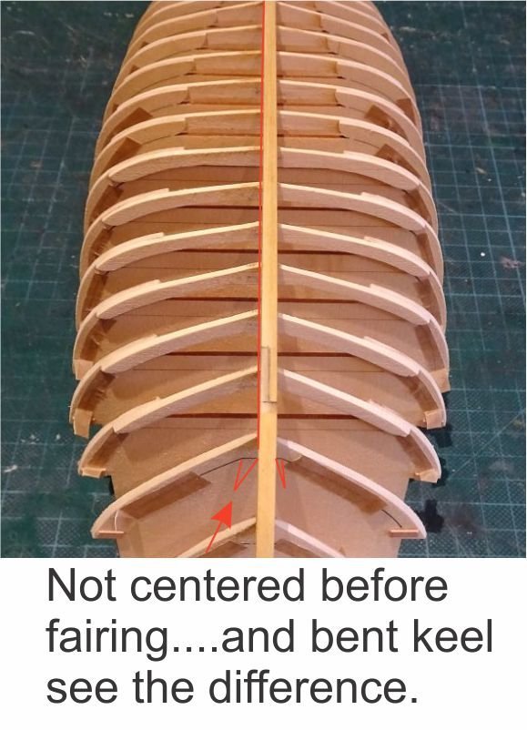
Round two coming up, I must try to do better.
Given how busy Chuck must be, what a great service he provides.
Thank you Chuck.
B.E.
- Wintergreen, bruce d, BobG and 5 others
-
8
-
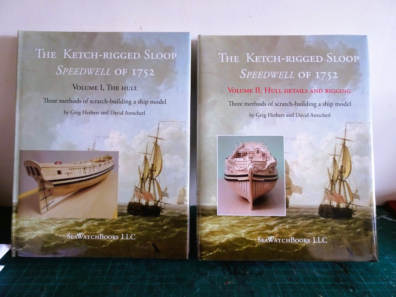
My latest purchase.
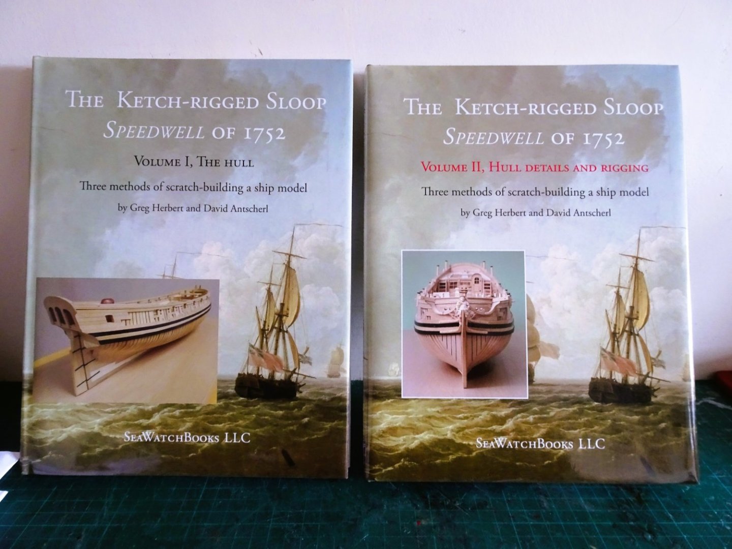
0189
Ordered 29th January received 2nd February, excellent service from Seawatch Books.
I enjoy reading Greg and David's books for their own sake, but I may just have secondary reason for buying.
B.E.
-
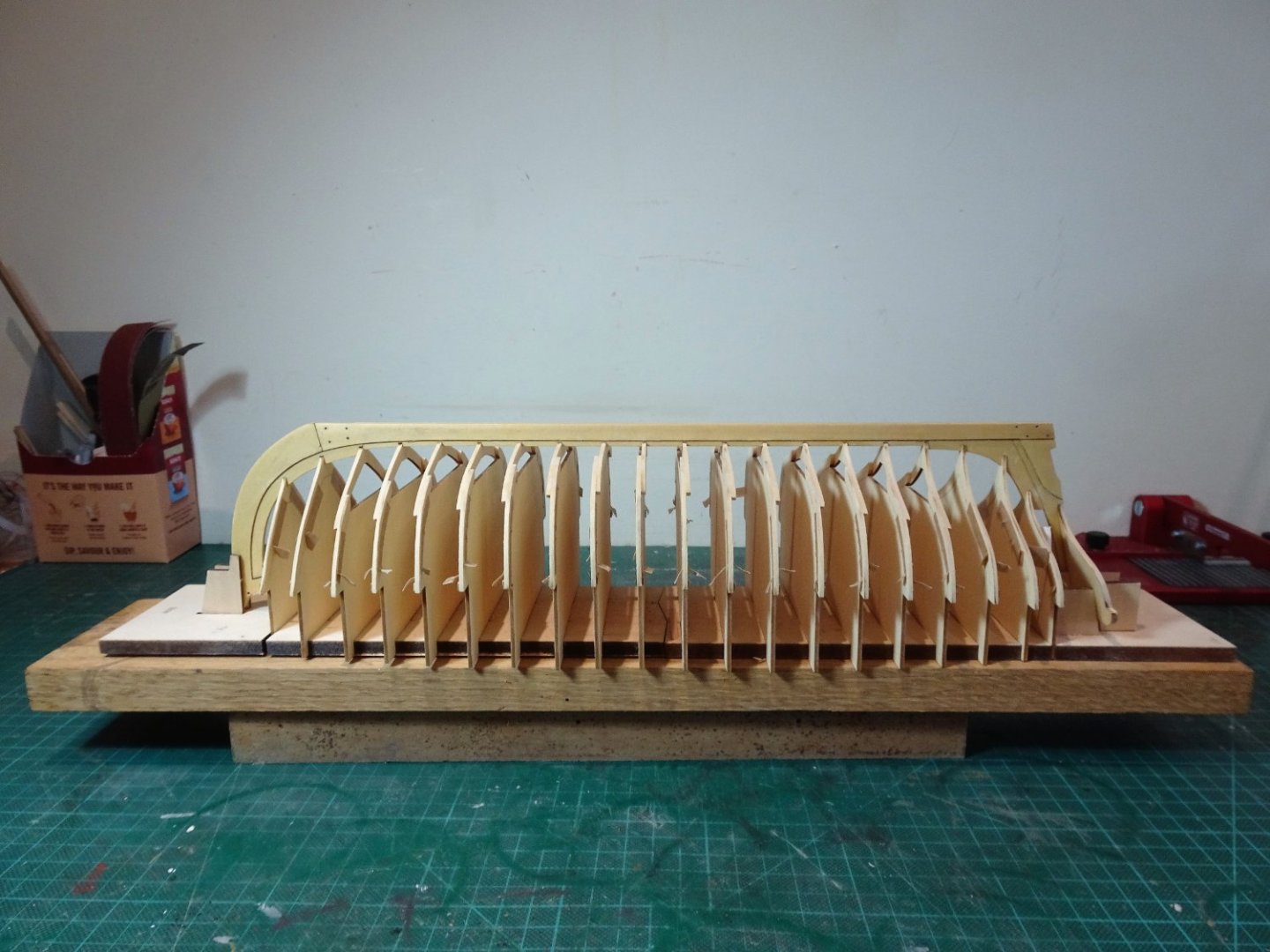
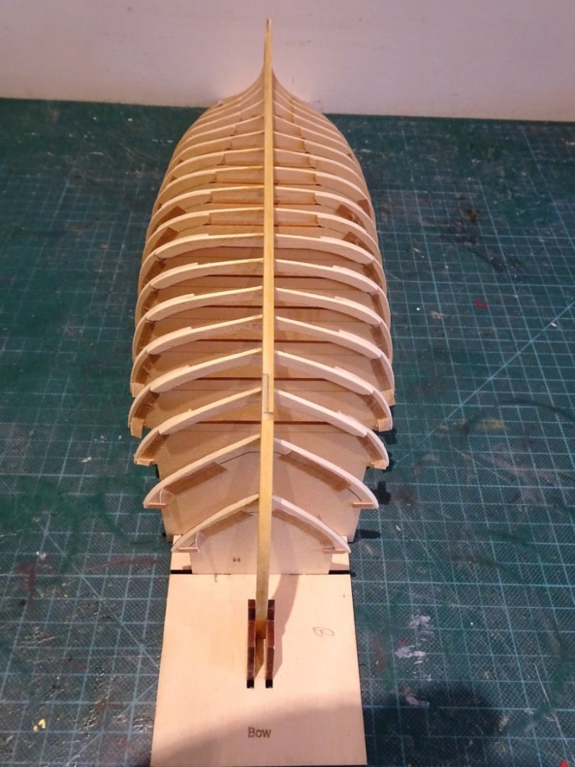
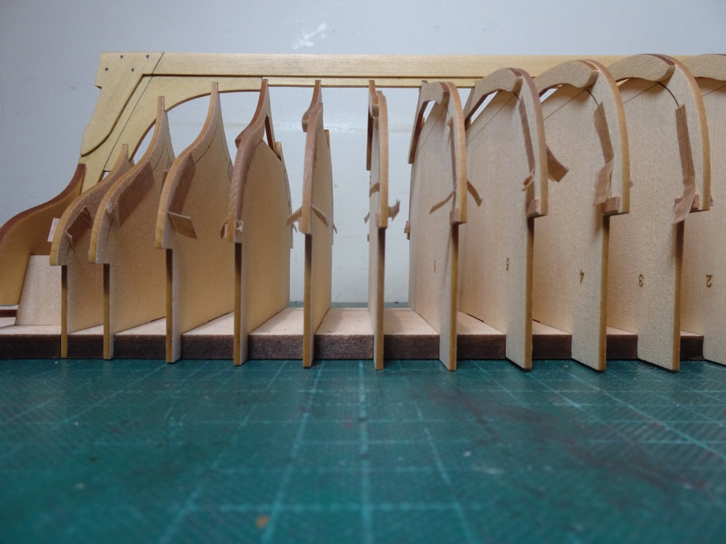
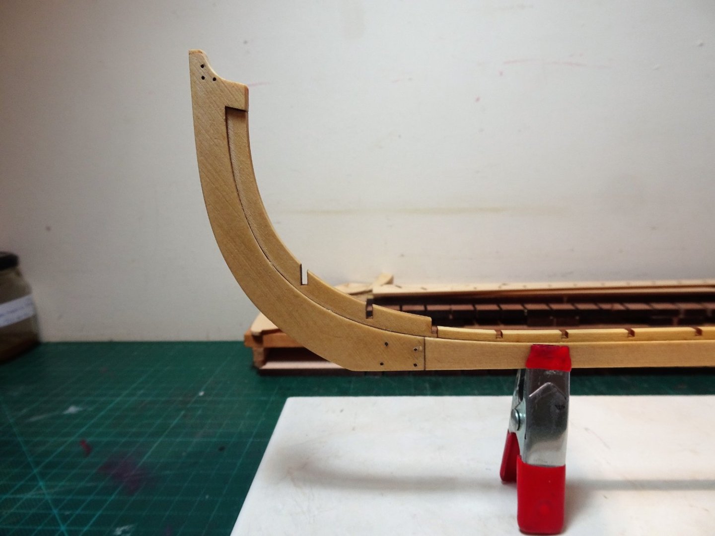
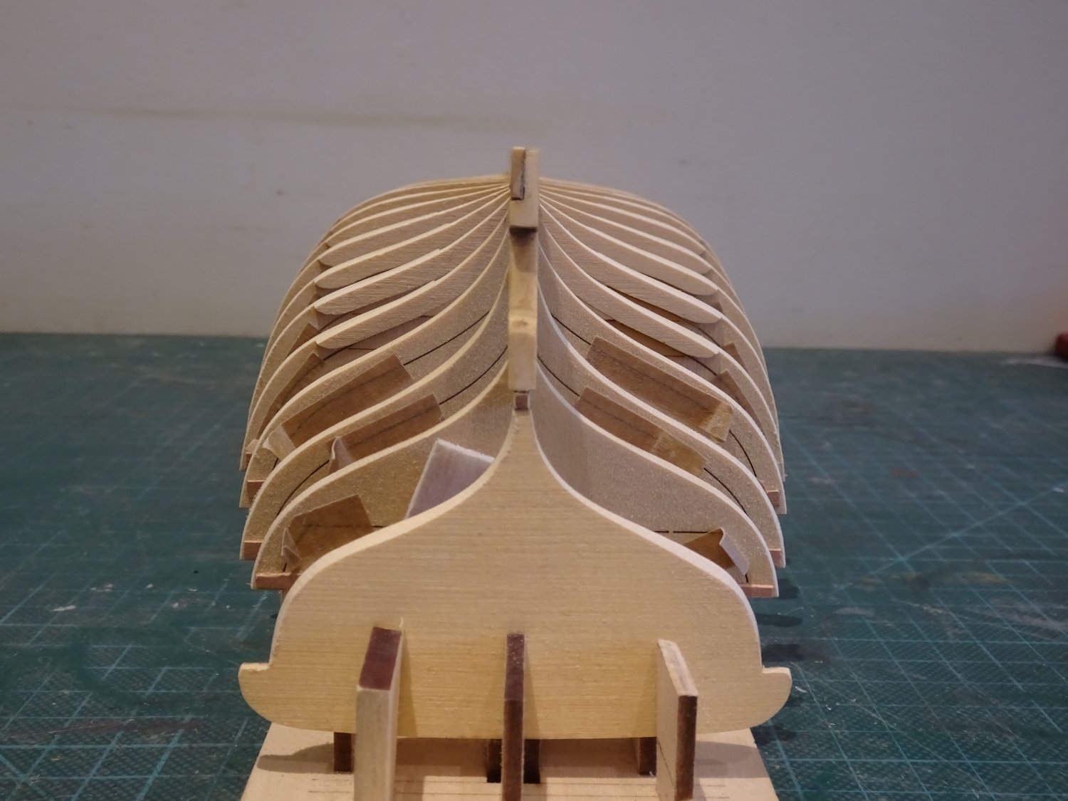
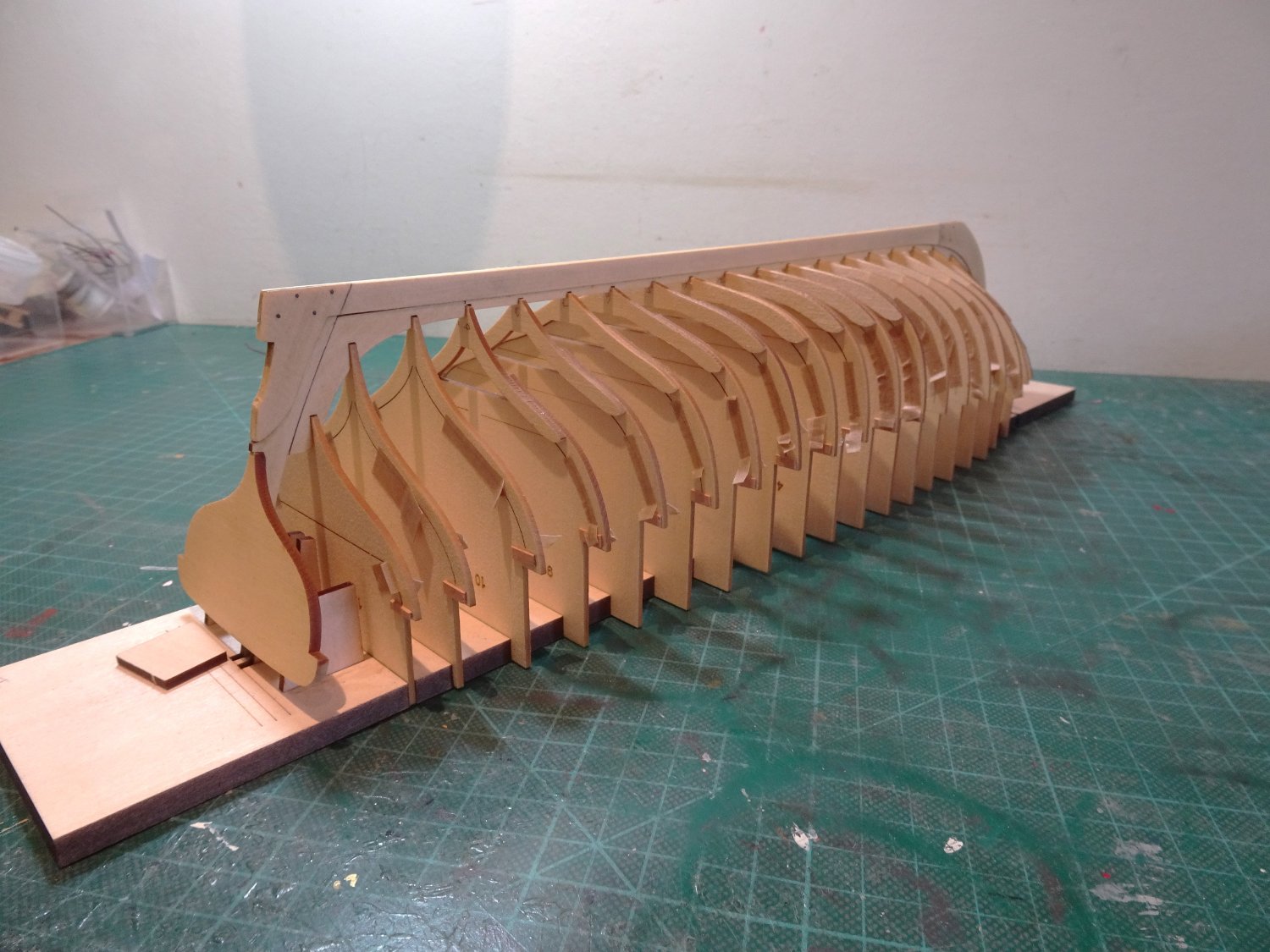
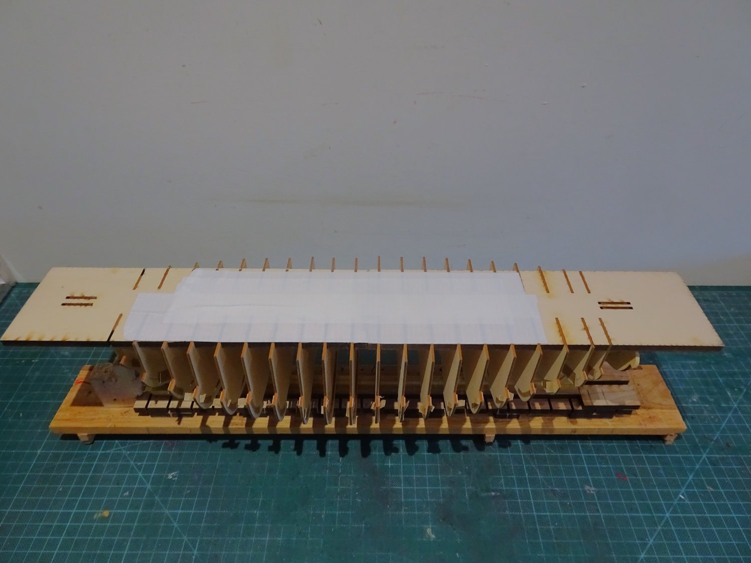
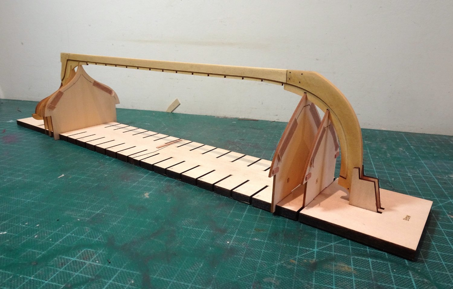
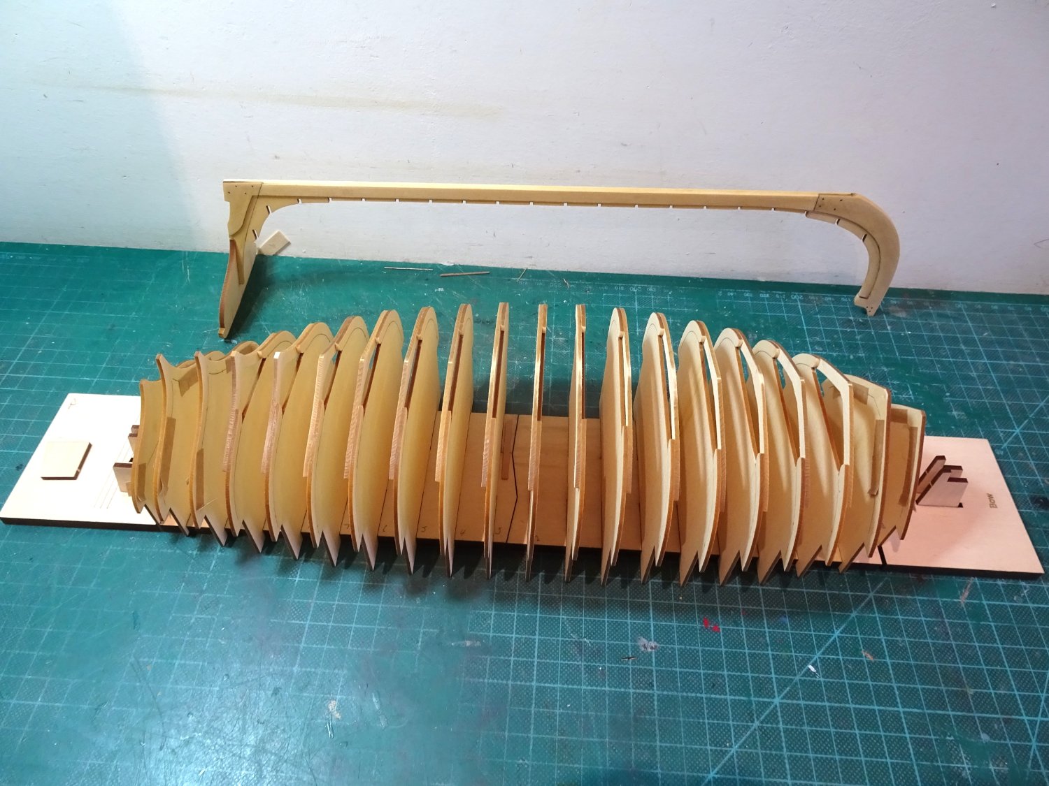
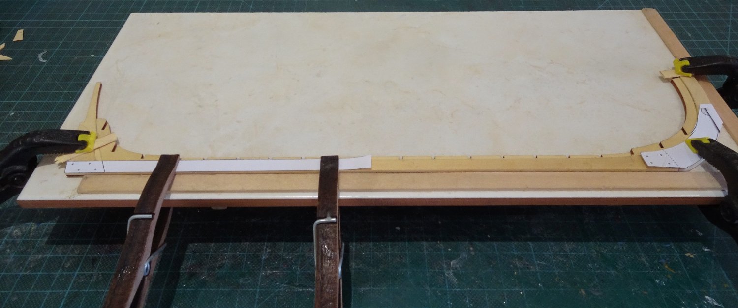
Post Seven
And it was all going so fine.
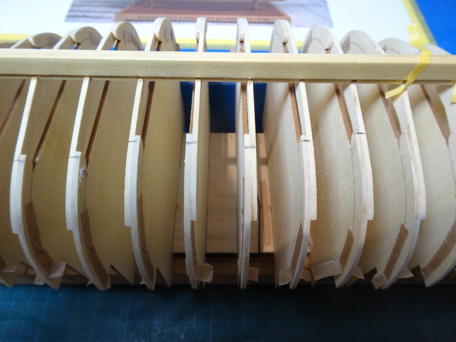
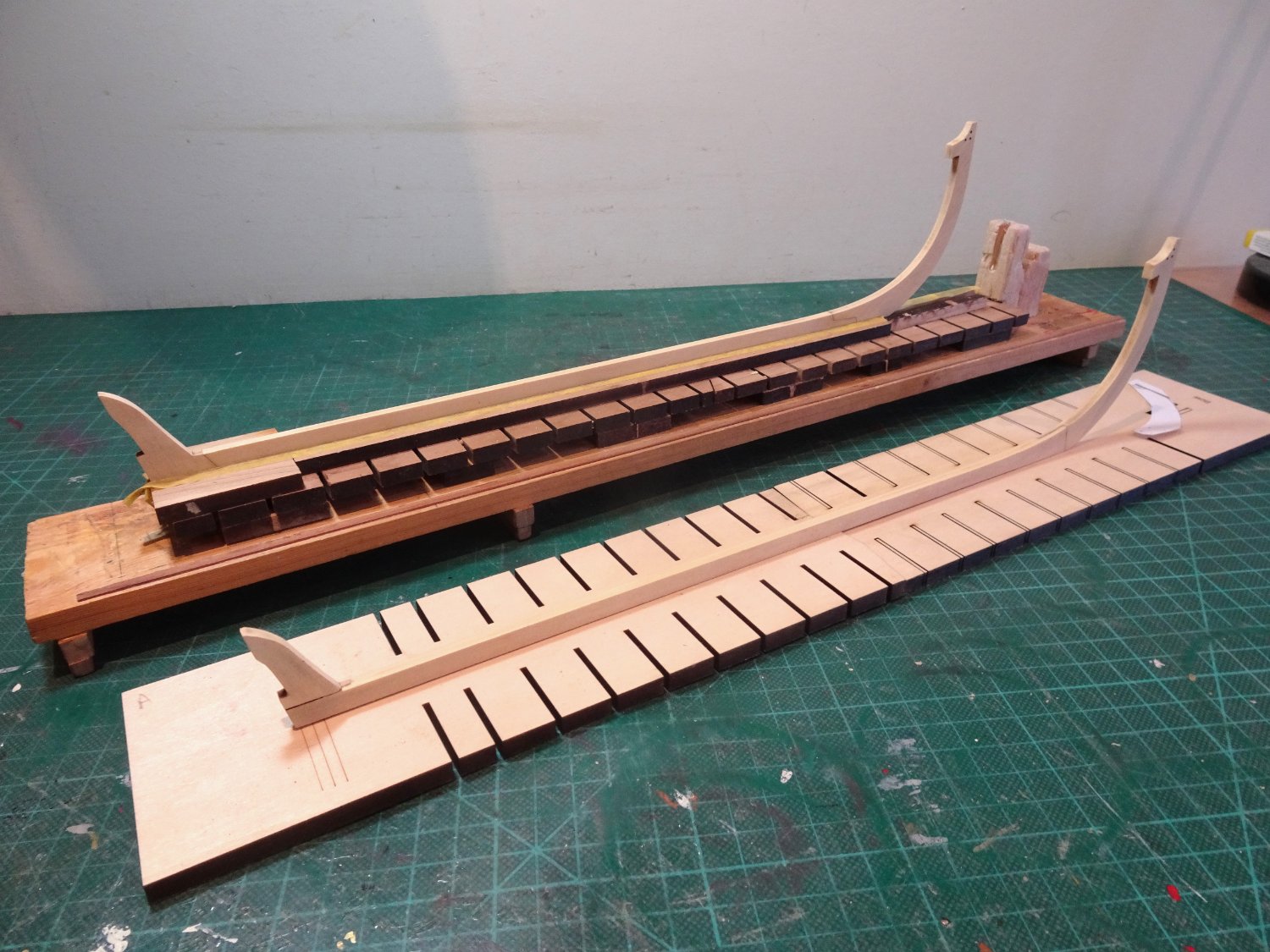
When I came to do the tick strips I quickly found that there was a variance between the overall length of frame edges port and starboard.
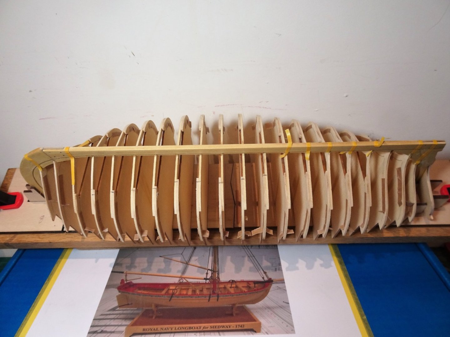
0179
The eight aftermost rear frames were fine, but ten of the forward ones were out between 2-4mm. The port side (with the hull inverted) were all shorter than the starboard side, suggesting that the frames are not centred.

0181
You can see here marked in pencil on the frames the length difference between the keel rabbet and edge of the floor timbers on the opposing side.
0182
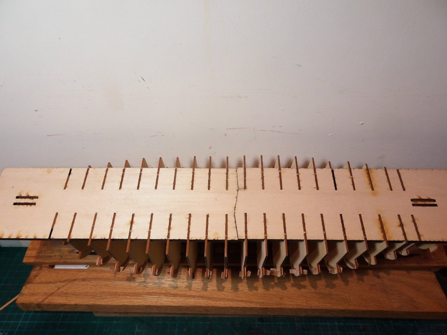
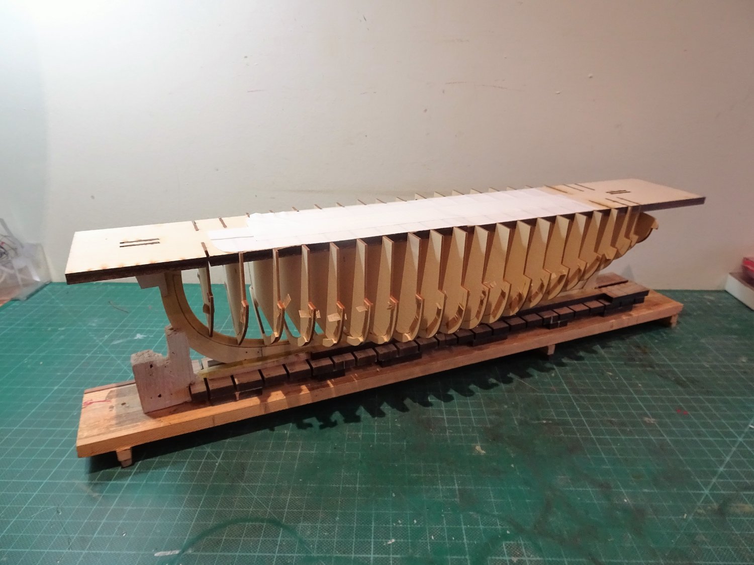
There is no wriggle room laterally in the frames they fit tight against the board slots, and the two halves of the board are squarely joined. The keel looks straight but as it stands, I can’t proceed on this basis.

0184
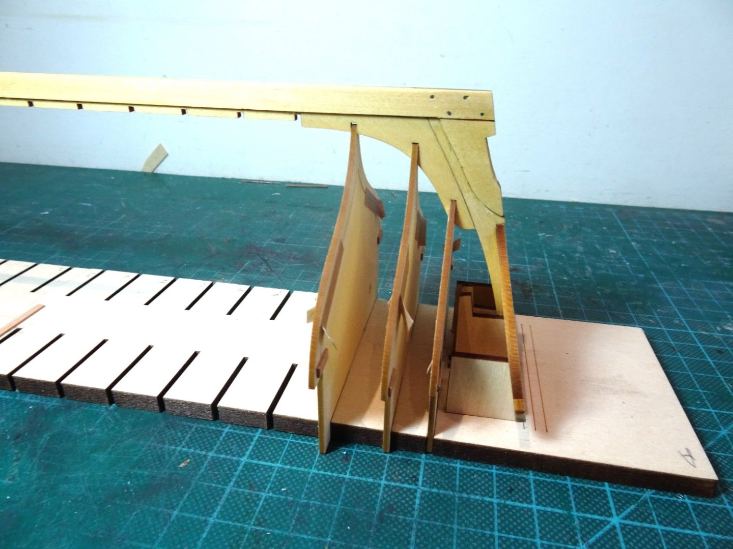
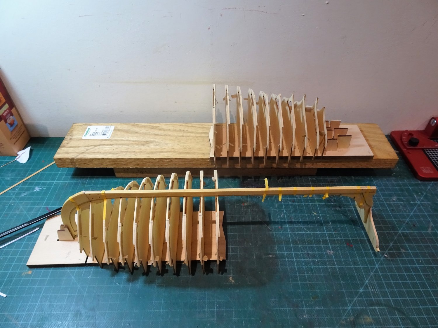
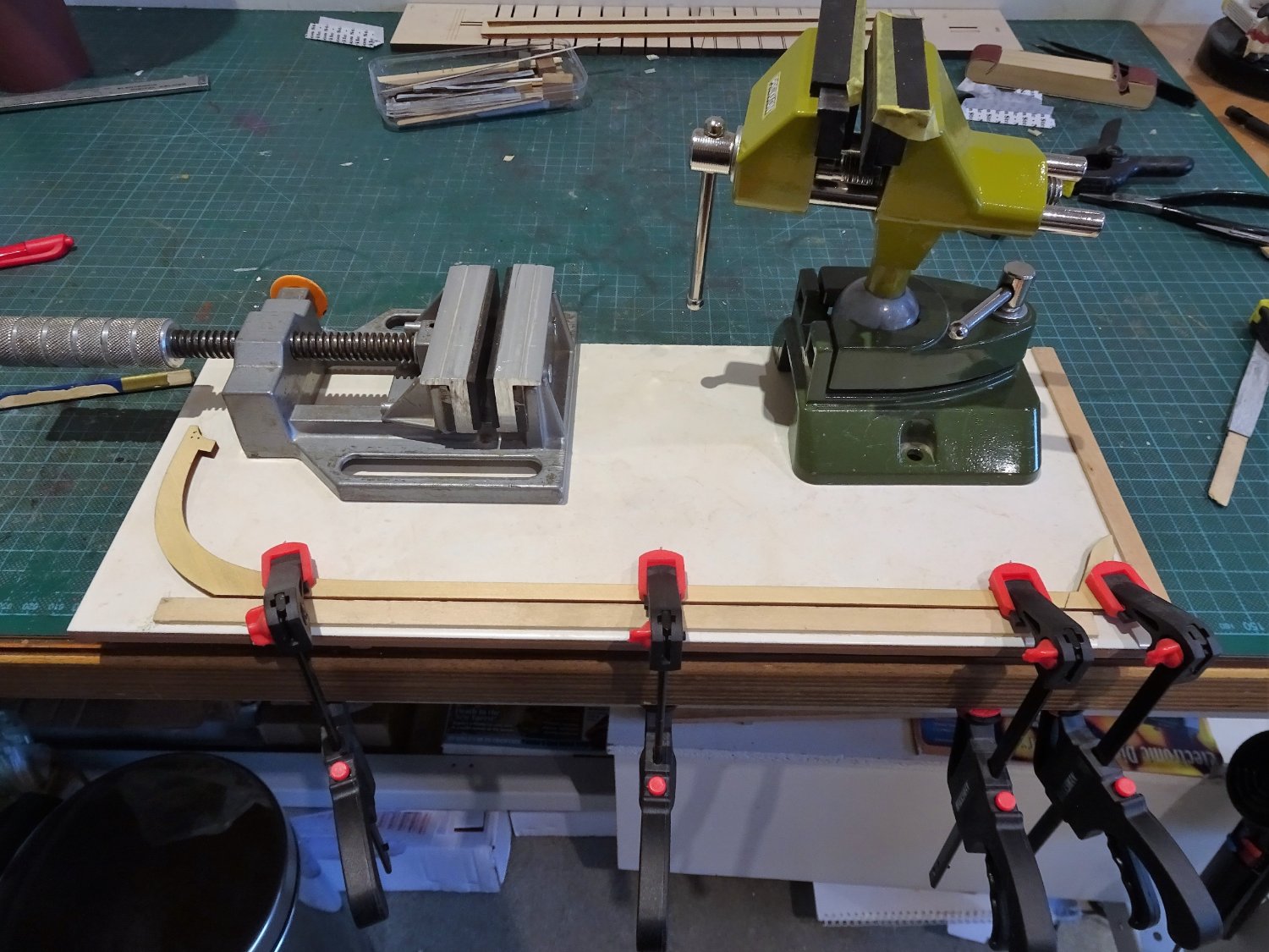
Nothing for it but to disassemble the forward half of the keel and re-set, hopefully with better results, but at least the fairing has been achieved.
0186
Fortunately, the keel separated from the frames fairly easily without any damage, but I’m still left with the issue of how to centre the keel without lateral movement in any of the frames.
It looks like I need to shave a fraction off the board slots relative to the offending frames to allow a degree of lateral movement. This would be easier and less risky than messing with the frame centres.
Before I proceed, any thoughts from those who have gone through this process?
B.E.
02/02/2023
-
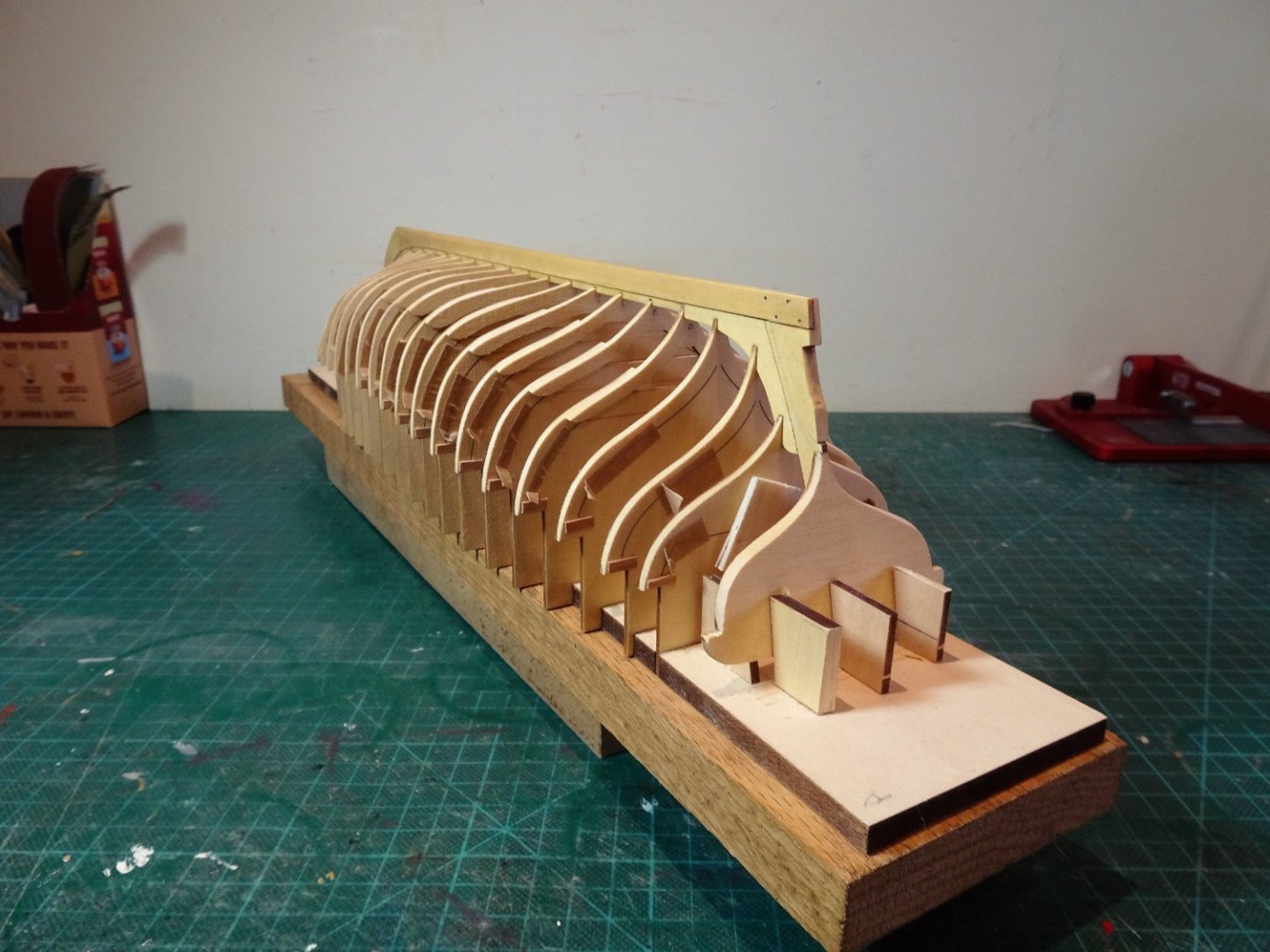
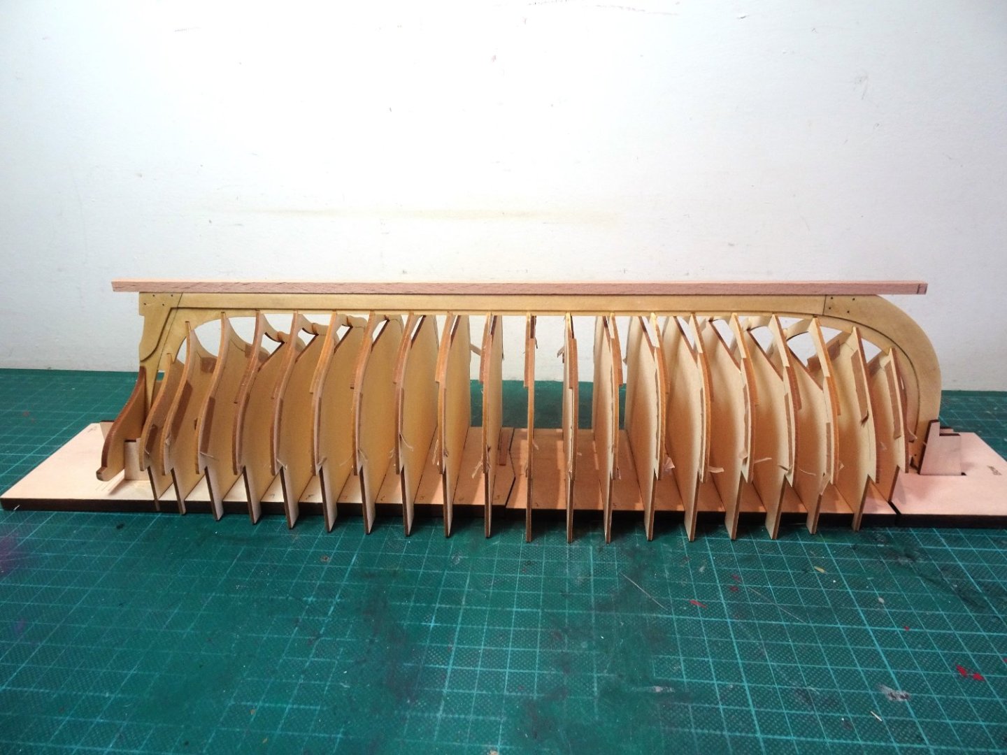
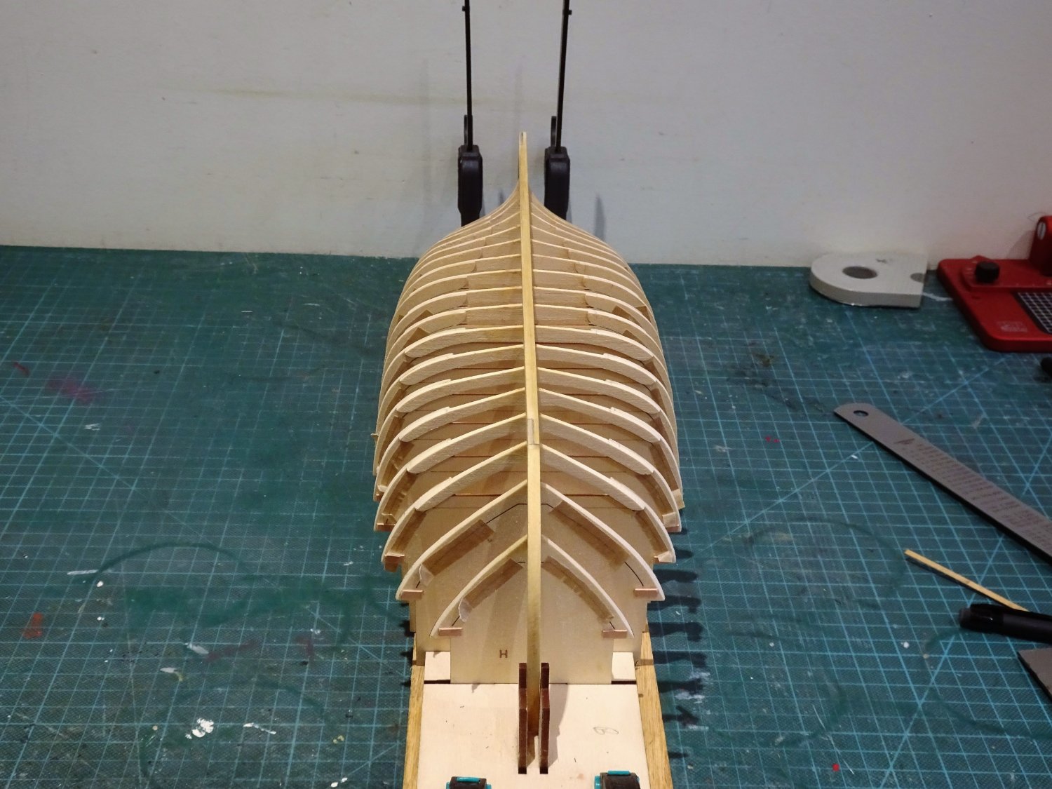
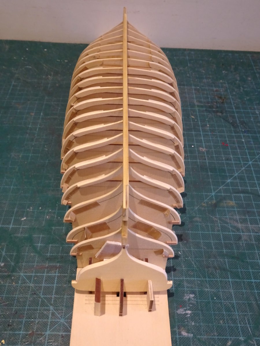
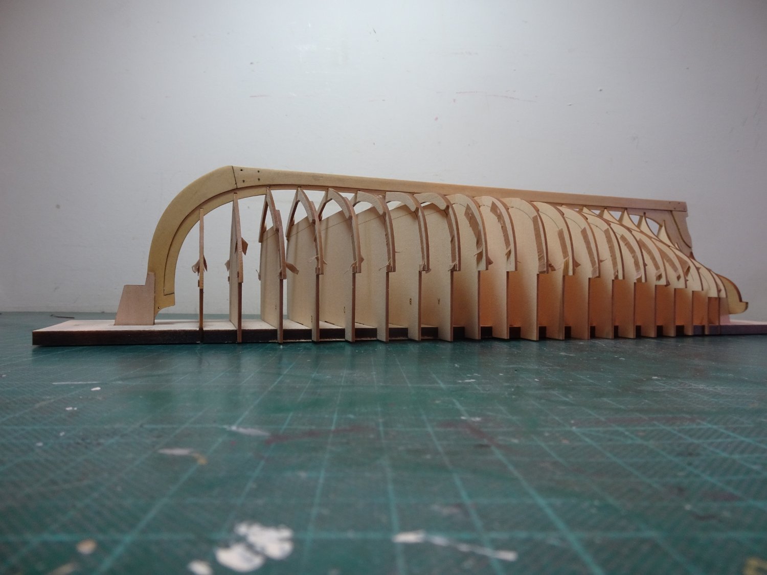
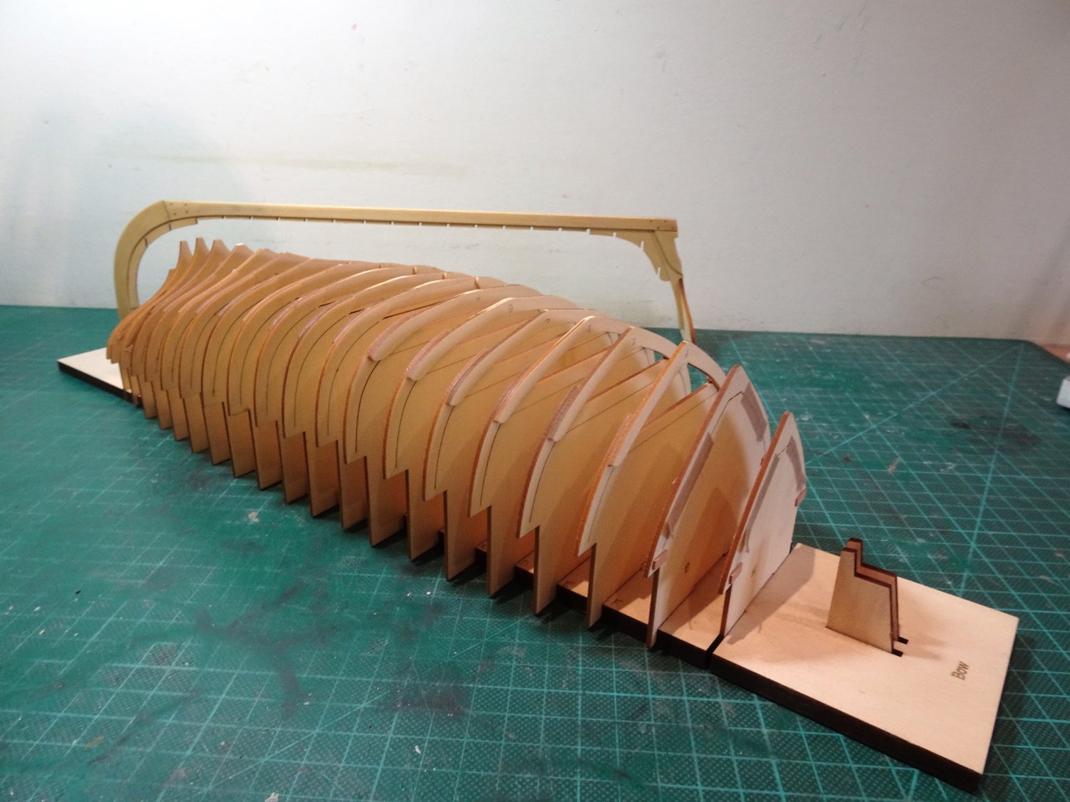
Post Six
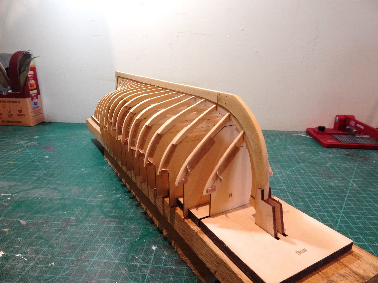
I always have a niggle of doubt completing this element of a build; is this the right point to stop, is it as good as I can get it?
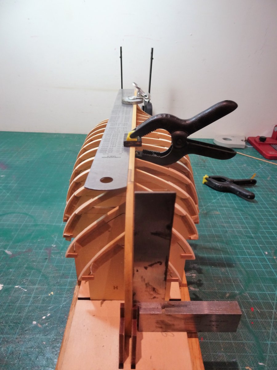
After several more hours, I think (hope) the fairing is complete.
Running my test plank across all frames from Garboard to sheer indicates a fair lie as far as I can see.

0164

0166
0167
0168
0170
0171
0173

0174
0175
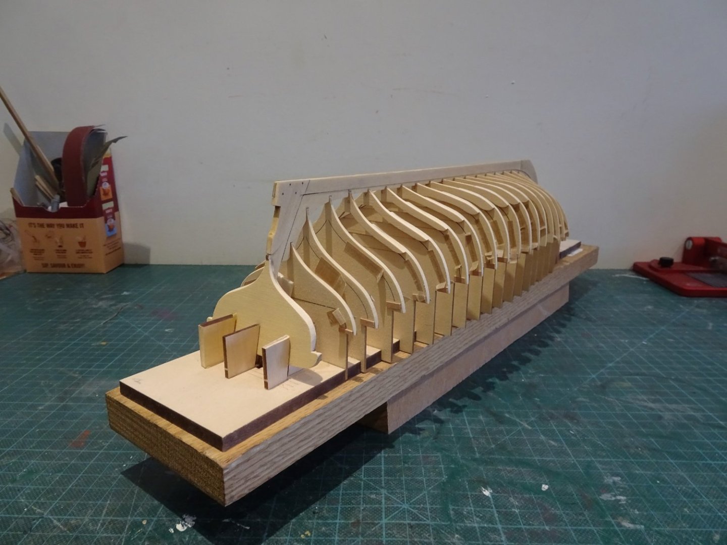
I did not experience any traumas with the frames; with the tips from Chuck they held good, and the balsa blocks between the frames helped, along with repeating the mantra – soft hands, keep it easy, to myself.
To get the most benefit from this project, even tho’ it’s not strictly necessary, I will follow Chuck’s plan of lining off the hull for planking.
Time to move to the next stage.
B.E.
01/02/2023
- gjdale, Wintergreen, Ryland Craze and 10 others
-
13
-
Thanks Mike,
The board is an integral part of the kit, and has been well designed by Chuck, but it can be disposed of once the planking is completed.
I will modify it to hold the hull in the upright position once that stage is reached.
B,E,
-
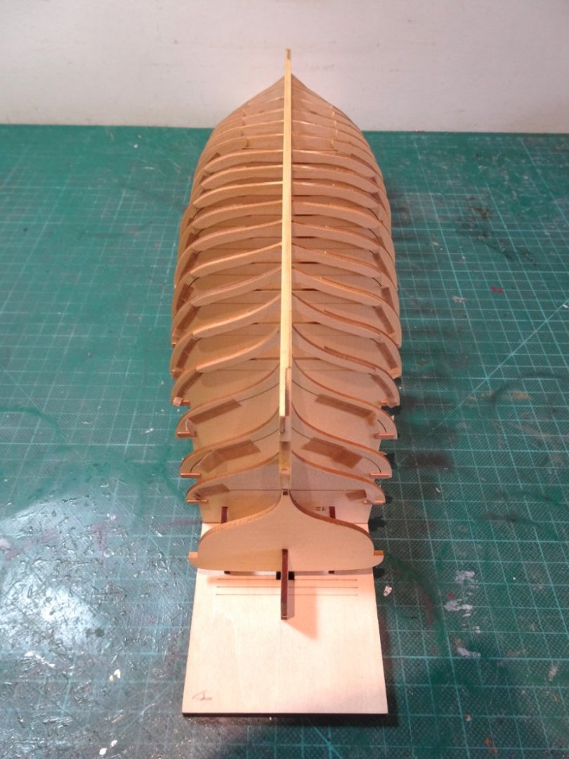
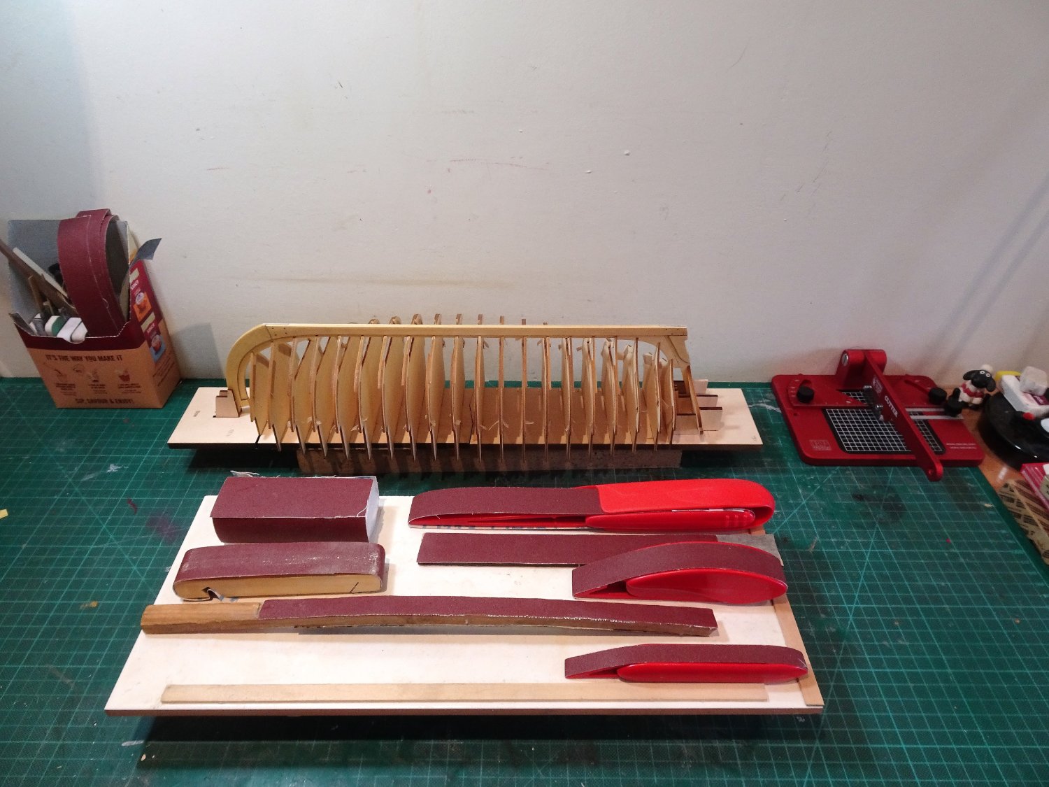
Post Five
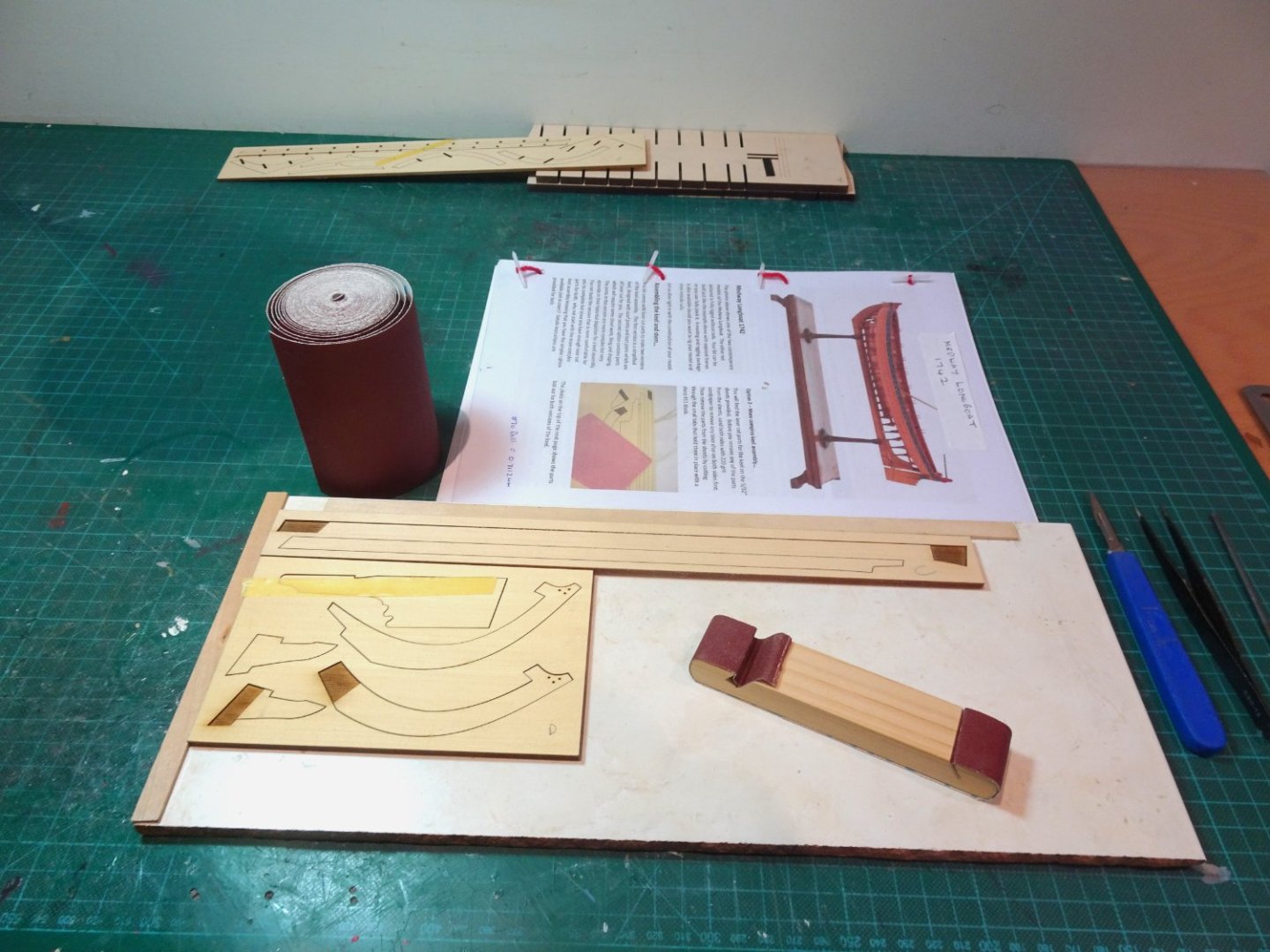
Preparations are made for the fairing process.
I will be using 320 grit aluminium oxide fabric backed sandpaper, which I buy on rolls. I also have some 240 grit sheets.
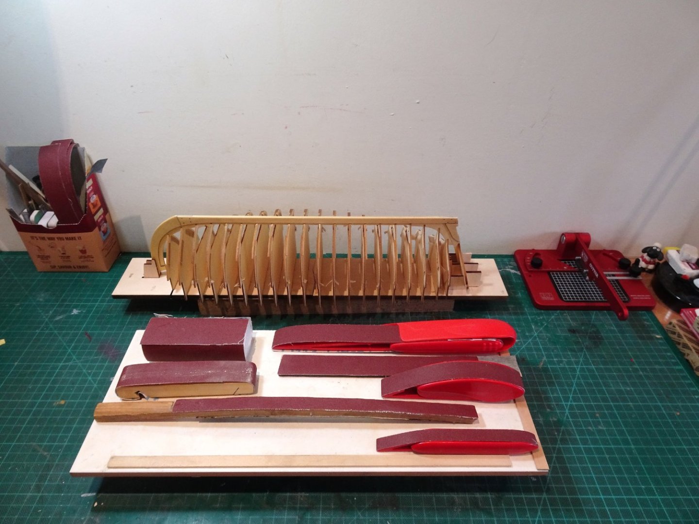
0154
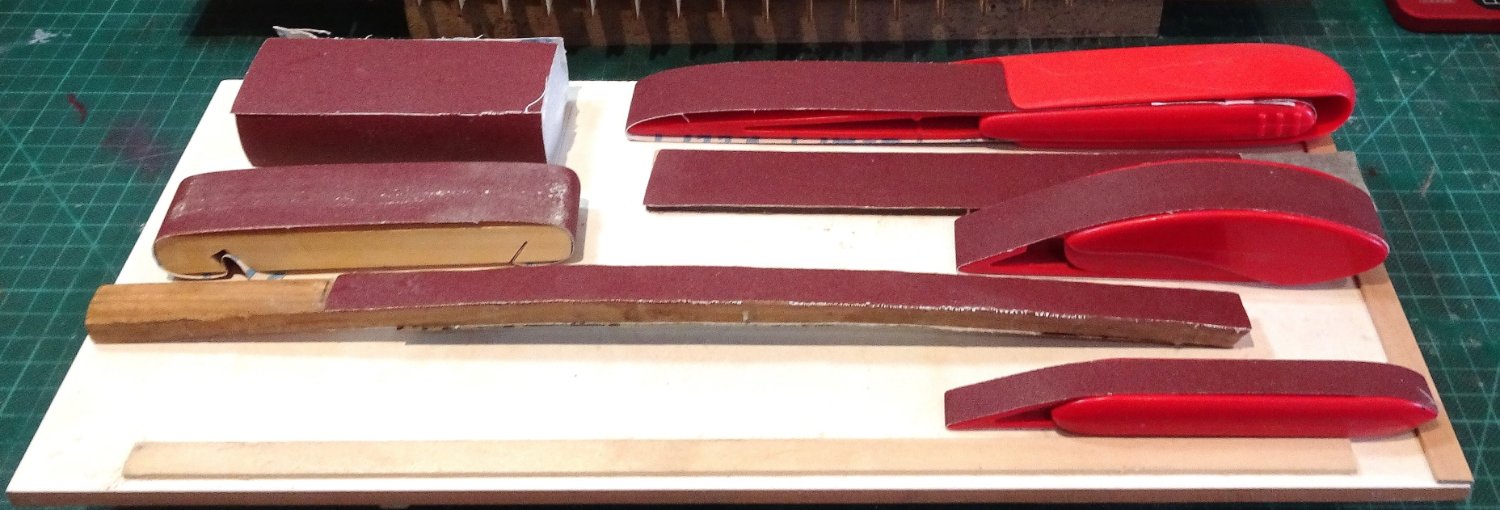
Many will be familiar with Model Craft finger sanders, the main drawback being replacing the sanding bands which cost around £9.00 for three, comprising a coarse, medium, and fine grade which for this job means two of the three aren’t of much use for the fairing process.
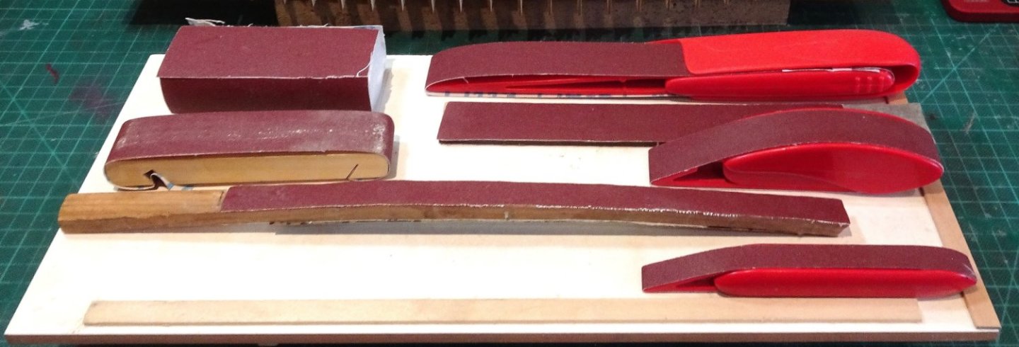
0152A
I make my own replacements using 320 grit off the roll with the ends joined together using ca and heavy duty parcel tape. (The same stuff used for securing the two halves of the building board.)
A lot cheaper than the replacement bands, and the exact grit grade required can be used.
You will all have heard of range anxiety in relation to electric cars, well I suffer from frame anxiety in relation to model ships.🙄

0156
Overkill maybe but I added small blocks of balsa between the frames to reduce flex.

0160
Fairing in progress. Cedar is a fairly soft wood, so the 320 grit is sufficient for the purpose.
0161
At this point I have probably spent a couple of hours fairing, but I’m not done yet.

0157

0163
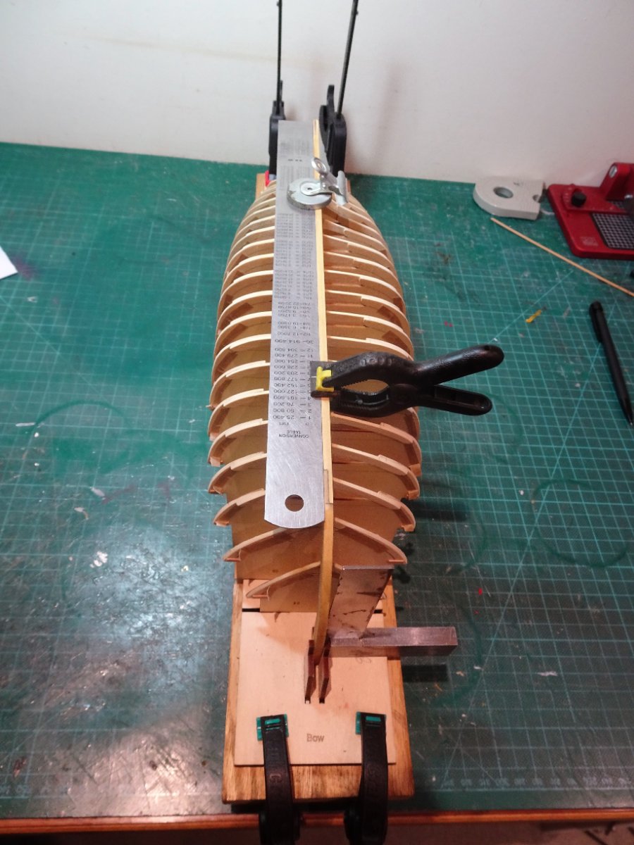
I use a thin planking strip to regularly check the run across the frames.
More than enough of that for today, tomorrow with fresh eyes I will use the strip to check across all frames at different levels.
B.E.
30/01/2023
-
-
You're welcome Håkan, best wishes for Tuesday, hope things go well.
B.E.
- mtaylor, Keith Black and Wintergreen
-
3
-
Loving what I see Håkan 👍
B.E.
- Wintergreen, Keith Black and mtaylor
-
3
-
Post Four
Being a belt and braces sort of chap I applied the tape and wooden tabs to all the frames in preparation for fairing.

0128
I spent time assembling/disassembling the frames and keel on the building board. I didn’t find it an easy task getting all the keel slots to sit fully down on the frames, but until this is done there is no point moving on. Some of the frames required a slight sanding where they fit into the keel slots.
0132
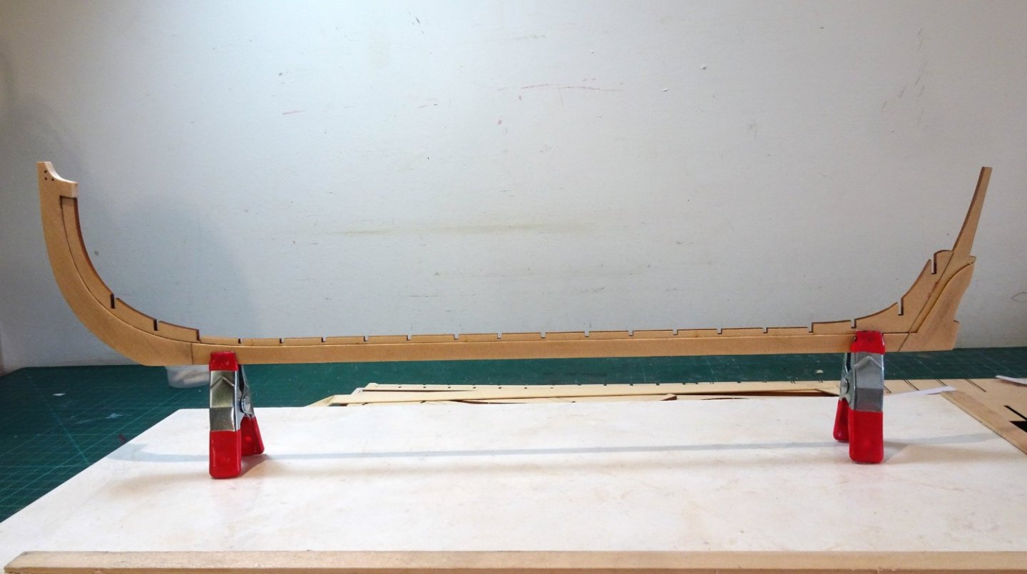
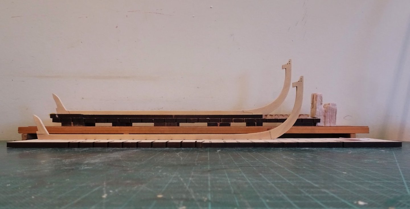
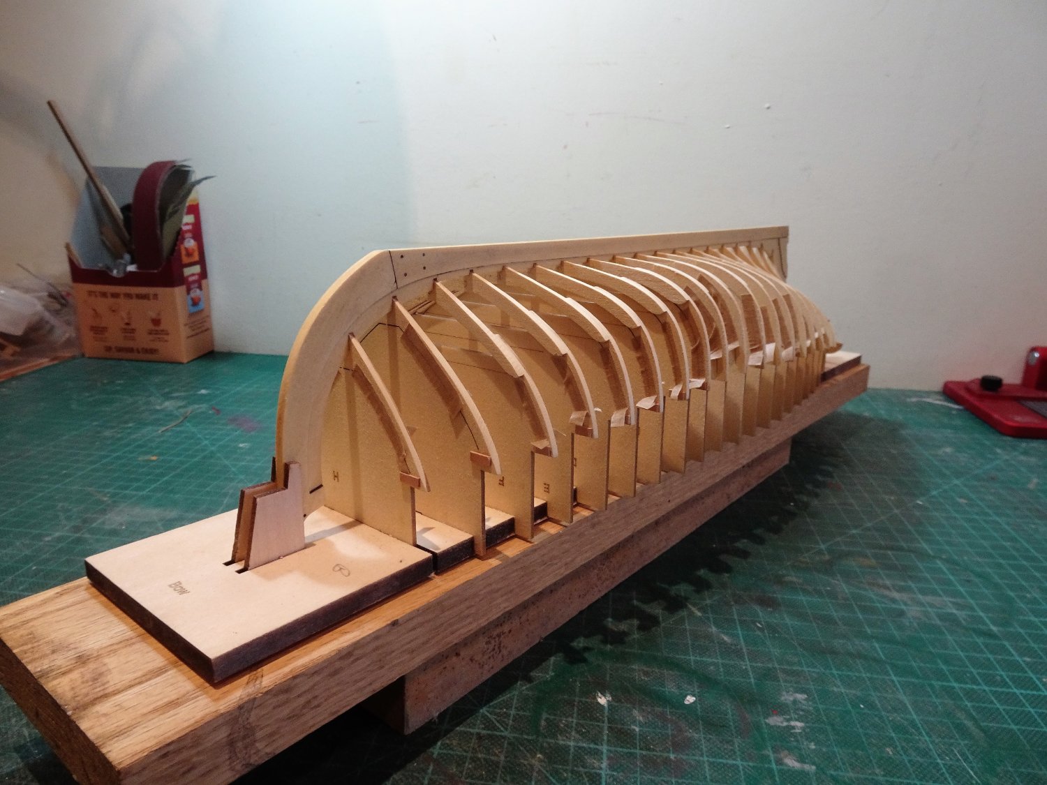
Once I could assemble the aft section in a fairly seamless manner, I proceeded to glue. This process took but a short time.
0139
No hogging in the keel.
0137
0145
… and no keel warp.

0146
Always a relief when this first part has been completed without mishap.

0136
I added an extra support for the transom using spare brace pieces.

0148
The hull is flipped for the application of tape to the underside of the building board.

0147
The tricky business of fairing beckons.
B.E.
27/01/23
-
Thank you Hakan, chuck and Paul.
@ Hakan - Those frames are delicate enough to make me twitchy when it comes to fairing.
That cutting mat has seen a lot of service, probably due for replacement, a lot of battle scars over the years.
@ Chuck - Love the Alaskan Cedar you are now using.
@ Paul - I still feel nervy starting a new project, even after all these years. Thank you for looking in on my build.
Regards,
B.E.
- Wintergreen, CiscoH, mtaylor and 1 other
-
4
-
Post three
Frame preparation is the next task.

113
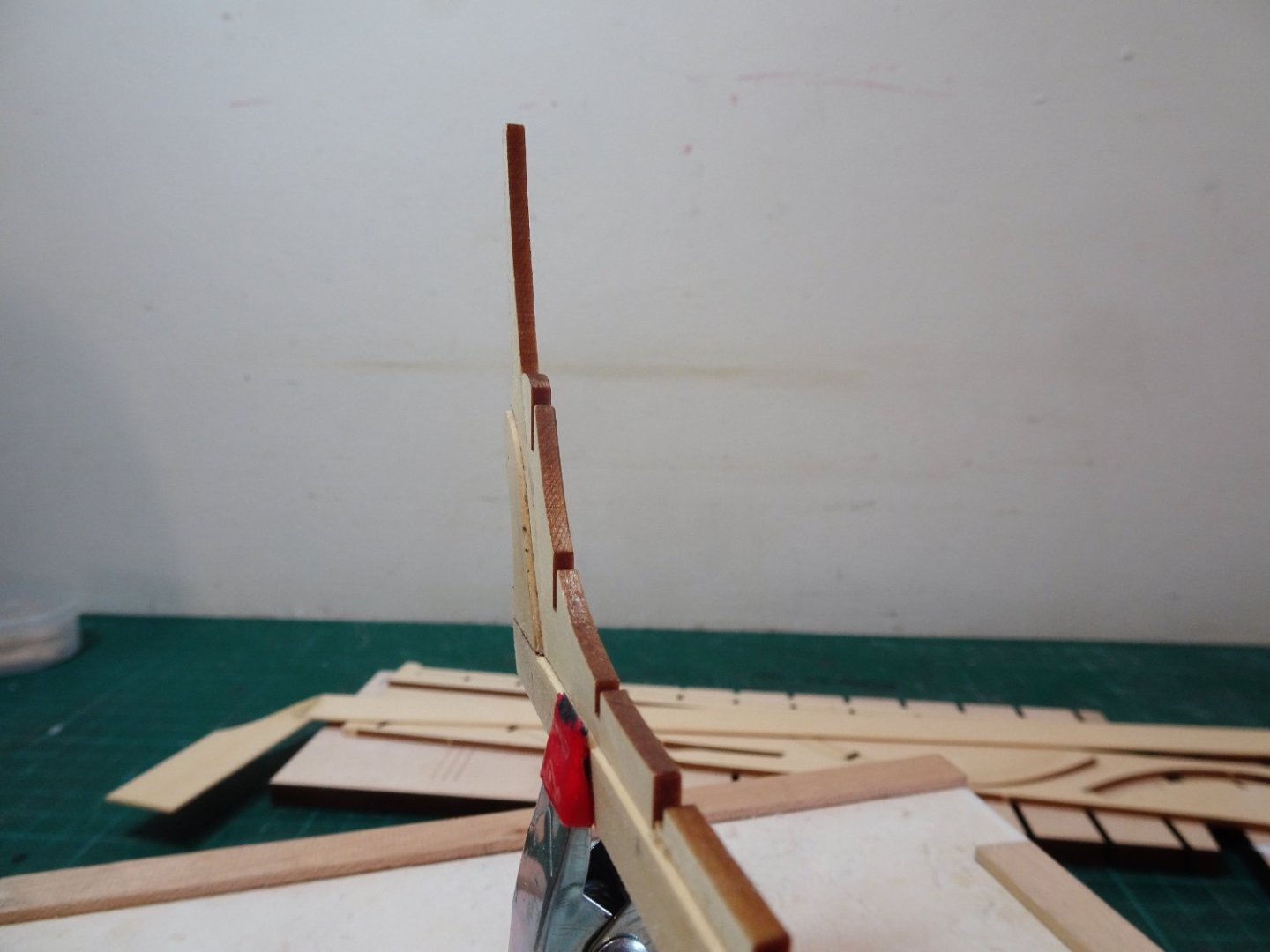
It starts with the fore and aft single frames. In accordance with the advice, tape is applied both sides of the frames to support the cut line during fairing, and small tabs are glued in place to support this weak area.
0112
Provided blocks are used to protect the transom.
0111a

0110
Dry test fitting of the keel, the first of many such tests before any glue is applied.
0109a
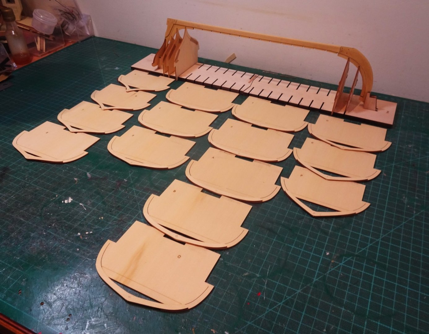
The double frames comprising Top timbers and floors are assembled.

0122
On the stern section board, the floor sections face aft.

0116
On the bow section board, the floor timbers face forward except for frames 1 and 2 next to the board join, which also face aft.

0126
The frames slot into the build board with very little need for adjustment.
I will now play around with the keel fit before I commit to glue.
B.E.
25/01/23
- JpR62, BobG, Wintergreen and 13 others
-
16
-
Carr Laughton has something to say about the decoration of Figures, which had been painted in natural colours, certainly from the 17th c altho' there may have been periods prior to 1770 where the fashion had lapsed in favour of gilt , varnish, or yellow paint.
During the late 18th c it is highly likely that figures were painted in natural colours, so I doubt that anyone could argue with the scheme on the Indy model.
The other consideration is aesthetics. Many of the beautiful 18thc models show unpainted figures, and personally as I like as little paint on models as possible I have always favoured the 'varnished' look.
Indy is slightly different as it is an all painted model and is perhaps better suited to a coloured figure.
It has really got to be in the 'eye' of the builder but I don't think there is an historical reason not to colour the figure.
B.E.
- thibaultron, yvesvidal, Canute and 8 others
-
11
-
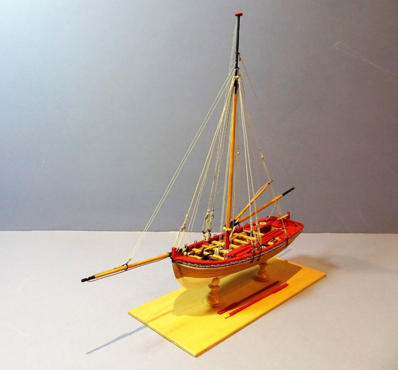
Thank you Glenn, no others of a similar scheme , oh, except the Queen Anne Barge, the 1:24 pinnace, the 1:48 Longboat, and the 1:64 Admirals barge.😉
Trouble is I rather like the effect of red ochre for the inboard works on these models, and after all in the 18thc Georgian Navy you could have any colour you like as long as it was Red Ochre.
Not used it before but I do like the cedar wood finish of this kit, it's a great substitute for Boxwood, and is now my second favourite wood.
Cheers,
B.E.
- Ryland Craze, mtaylor and glbarlow
-
3
-
Thanks Captn, it's a fairly common approach, used by others in the group build section, but it's one I've used over quite a few years , similar adaptations have all sorts of applications in ship model building.
Regards,
B.E.
- mtaylor and CaptnBirdseye
-
2
-
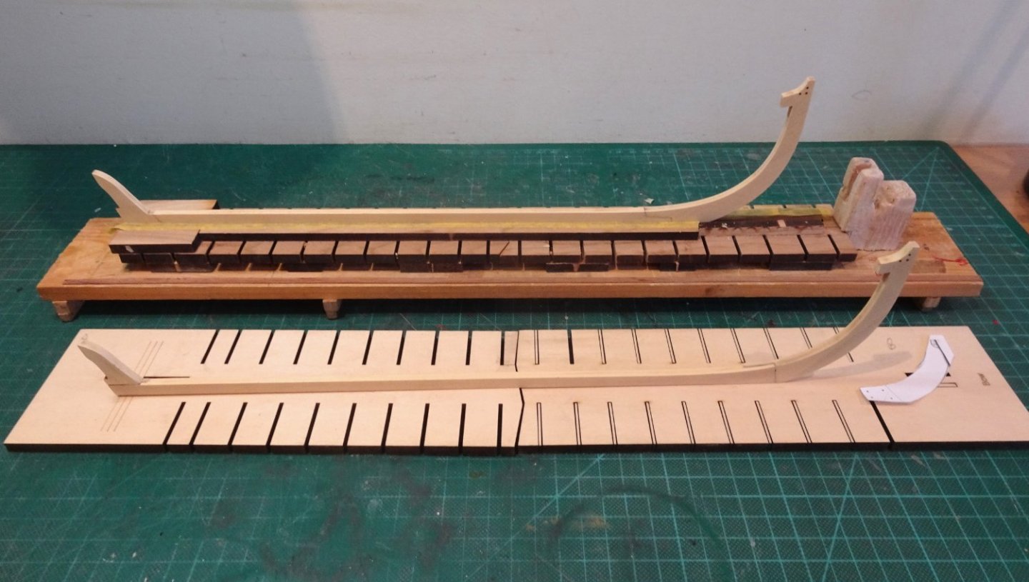
Post two
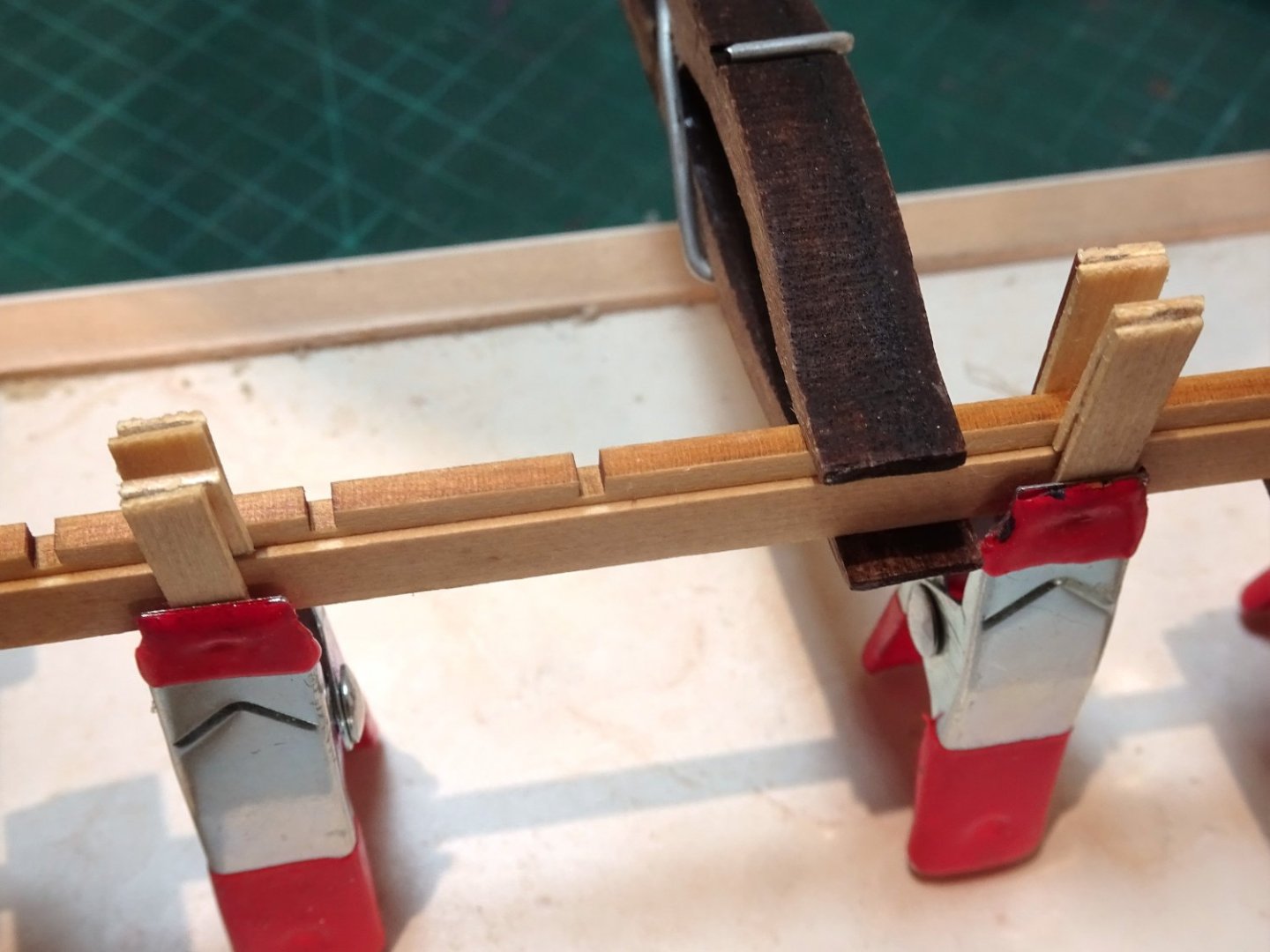
The keel is completed by the addition of notched strips into which the frames will be fitted. These need to be centrally placed to form a rabbet either side.
I used strips cut from spare 1/32” cedar sheet to provide spacer pieces to ensure the fit is central to the keel.

065
The stem notched section is fitted first.
067
The first part of the sternpost addition is fitted next but has been sanded a little to provide an adequate rabbet.

073
The second part of the stern fitting also sanded a little to enhance the rabbet.
080
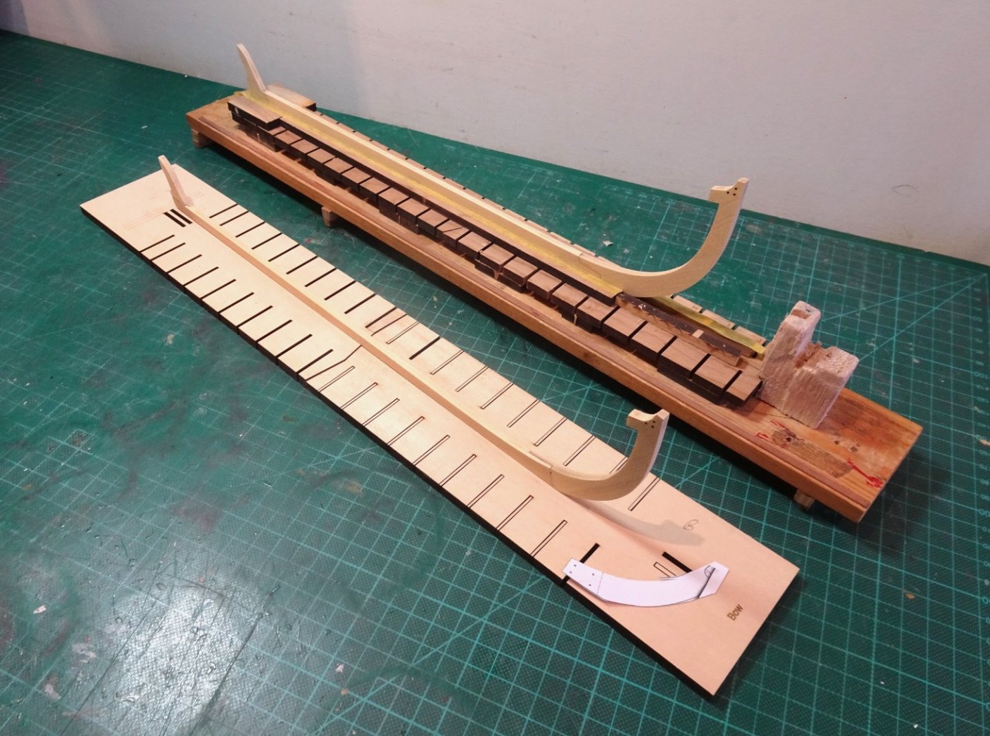
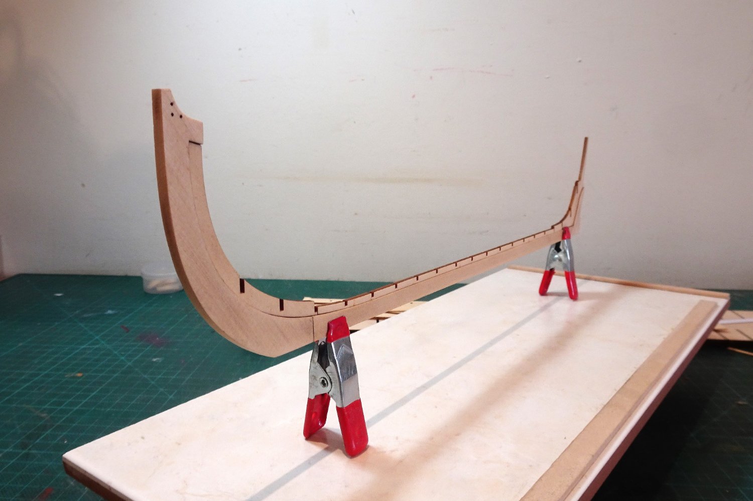
The long keel section is fitted lastly and is centred by use of four spacing jigs along its length.
083
The long keel section fitted perfectly along the keel without the need for any adjustment.

084
So far, So good.
087
Chuck specifically mentions ensuring an adequate rabbet at the stern.

091
Templates used to mark the bolt holes through the lap joints. Using it both sides aligned the holes and allowed for through drilling. I used a 0.70mm ø drill, and a coat of wipe-on was then applied.
092
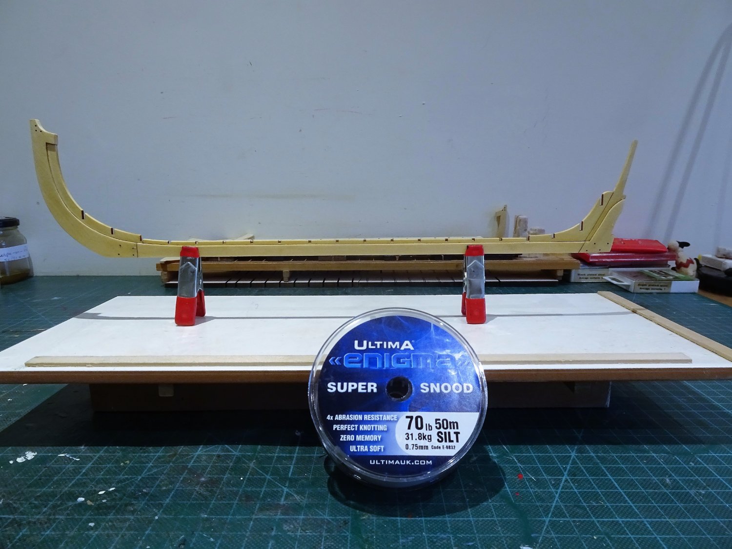
There seems to be some variation in the line to use for the bolts. The instructions say 25lb monofilament line, but Chuck’s own log mentions use of 201b or as an alternative 22 gauge copper wire.
The kit list indicated 10lb, 20lb, and 40lb black filament but I could only find 10lb filament. 28 and 24-gauge wire was also provided.

095
In the end I settled on 70lb/31.8kg (0.75mm) monofilament line.
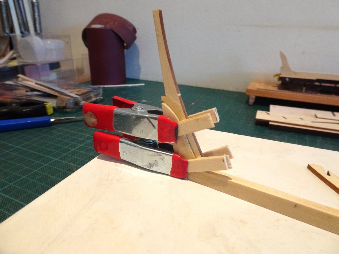
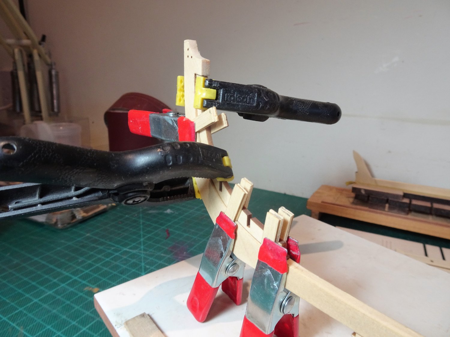
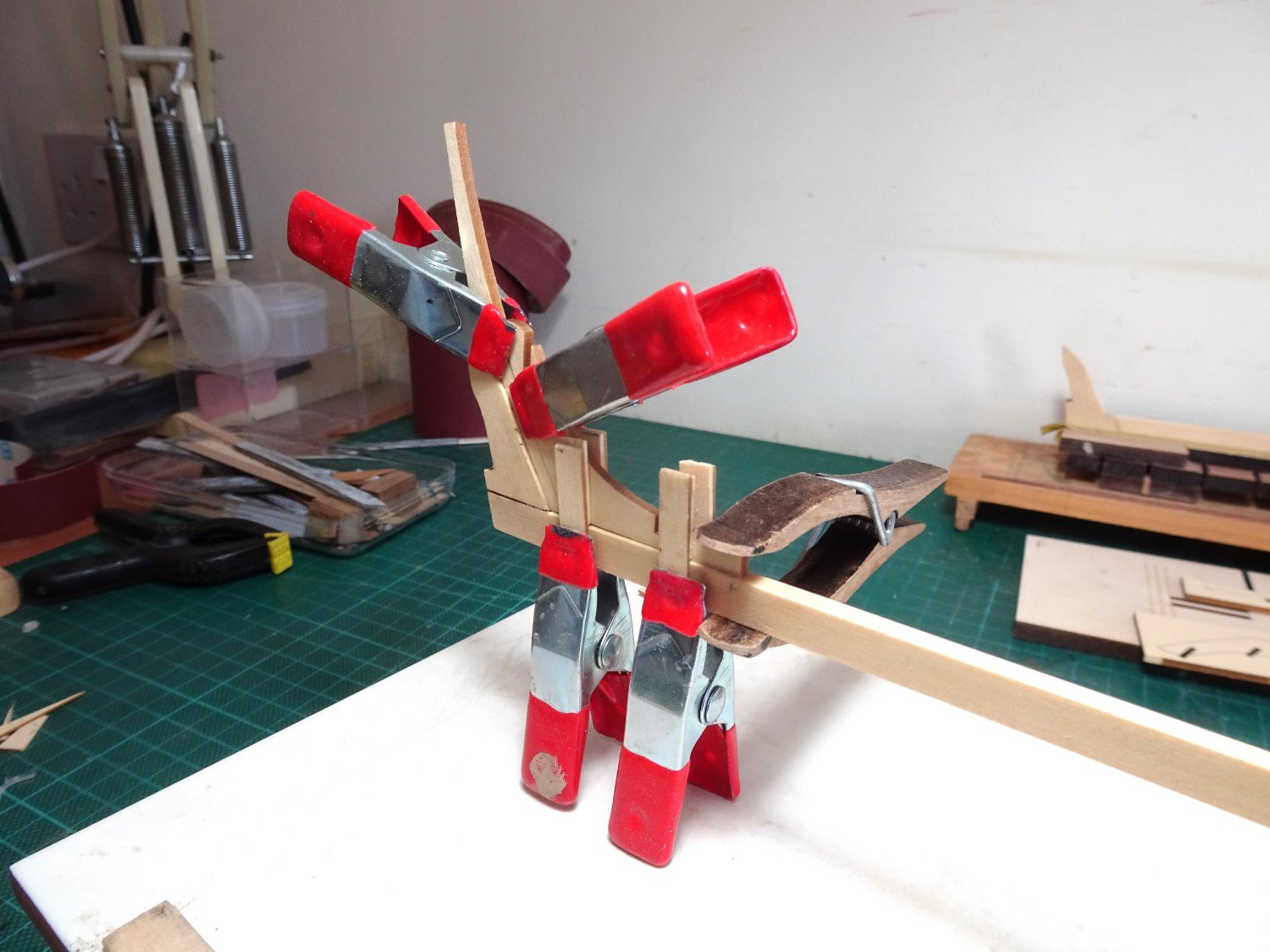
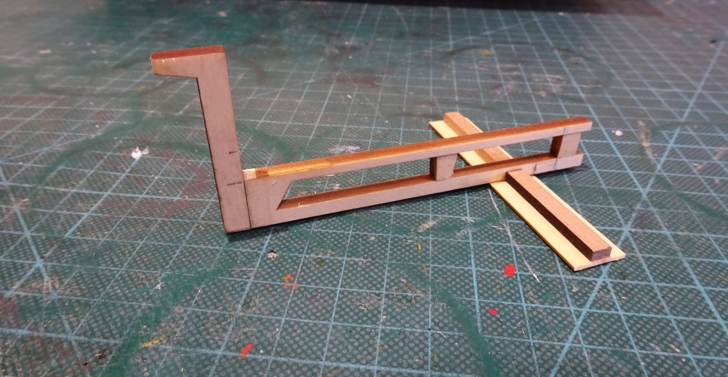
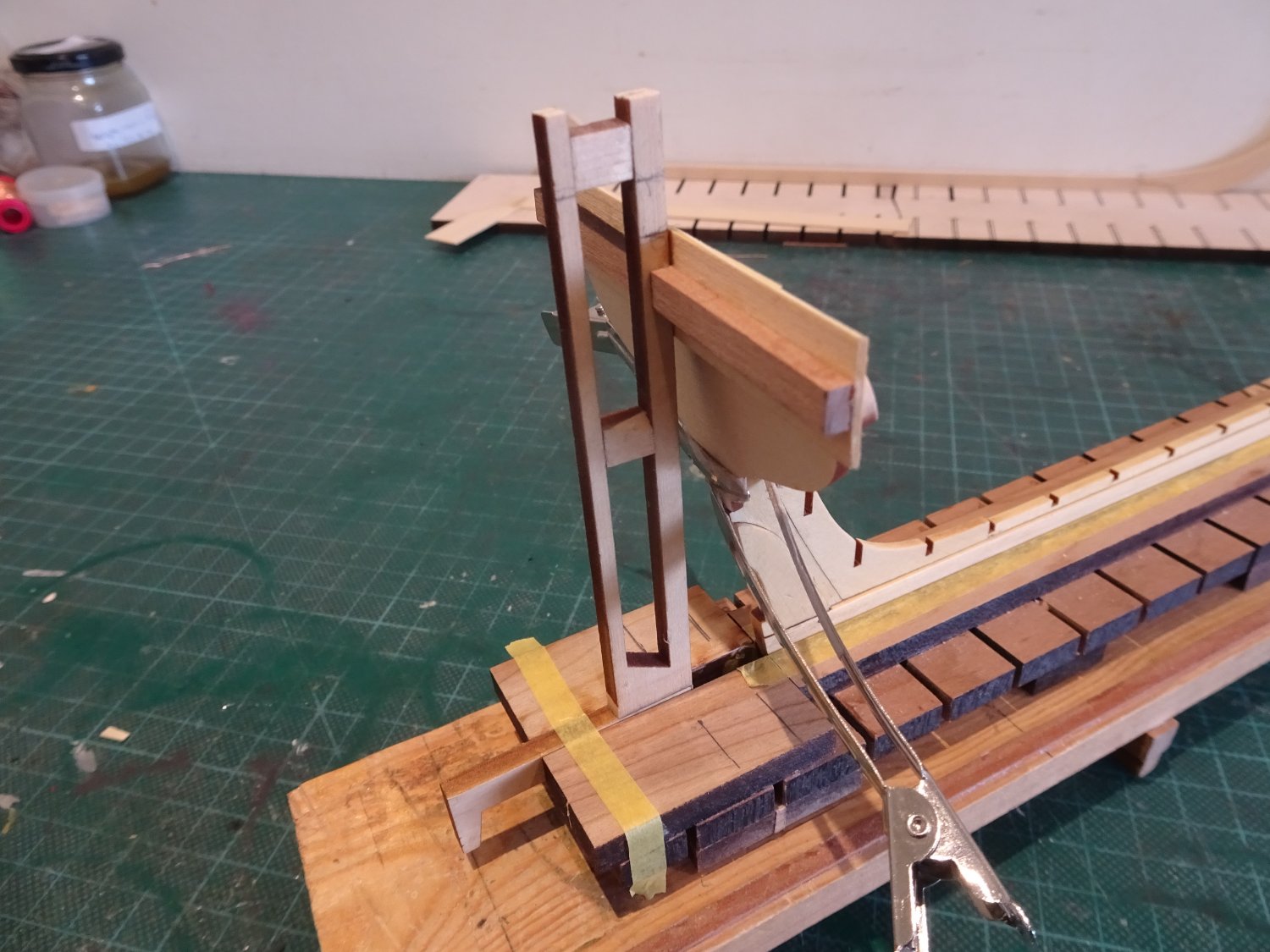
The final part of this section is attaching the transom. There is a useful vertical shallow slot lasered into the fore face of transom which assists both positioning and gluing the piece into place.
The other main consideration is ensuring that the transom sits squarely to the keel at 90 degrees.

097a
I created a simple jig to check the square, made from bits of fret from the kit.

0101
0102
0105
My Queen Anne Barge build board proved useful for aligning the Transom.
A further coat of wipe-on will now be applied before moving on.
B.E.
23/01/23
-
Thank you, shipman,
I’m not sure I agree with you about this kit being hackneyed on MSW.
Compared with many other builds there are relatively few in active progress, and even less completed.
The decoration is a minor element of the build, which produces a superb version of the contemporary model in the NMM.
I don’t see much scope for giving the build a different treatment that would improve on the basic model. If you have anything in mind, I’m all ears.
As a serial kit basher, the Syren kits are the only ones I have not felt the need to make any significant modifications to.
I am considering whether to fully plank of leave partially in frame to match the Royal Barge, but that’s about it.
A long time ago I copied this photo from a log.
I don’t recall whose build it is now, but I liked the display of the Longboat very much.
Sorry to disappoint you, but I hope you will still look-in periodically to see progress.
Regards,
B.E.
- jpalmer1970, Wintergreen, gjdale and 7 others
-
10
-
Post One.
The journey begins.
Parts one and two of the guide have been printed out and a supply of 320 sandpaper obtained to prep the keels. A fresh mix of wipe-on-poly has been made up so it’s time to get going.
023
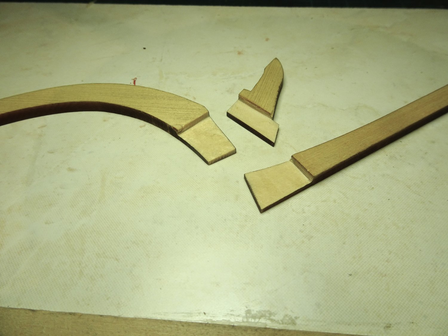
I have decided to build both keel versions, simply because they’re there.
I quite like the look of the scarph joint version but as Chuck has gone to the trouble of creating the more authentic lap joint arrangement, I hope to use that one.
032
I used a No11 blade in the scalpel to pare down the lap joints and finished with 320 paper.

036
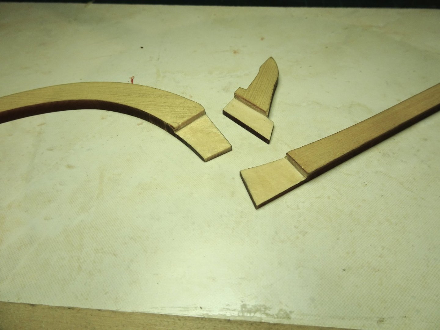
The cedar cuts cleanly, but I got through 10 blades fettling the lap joints.
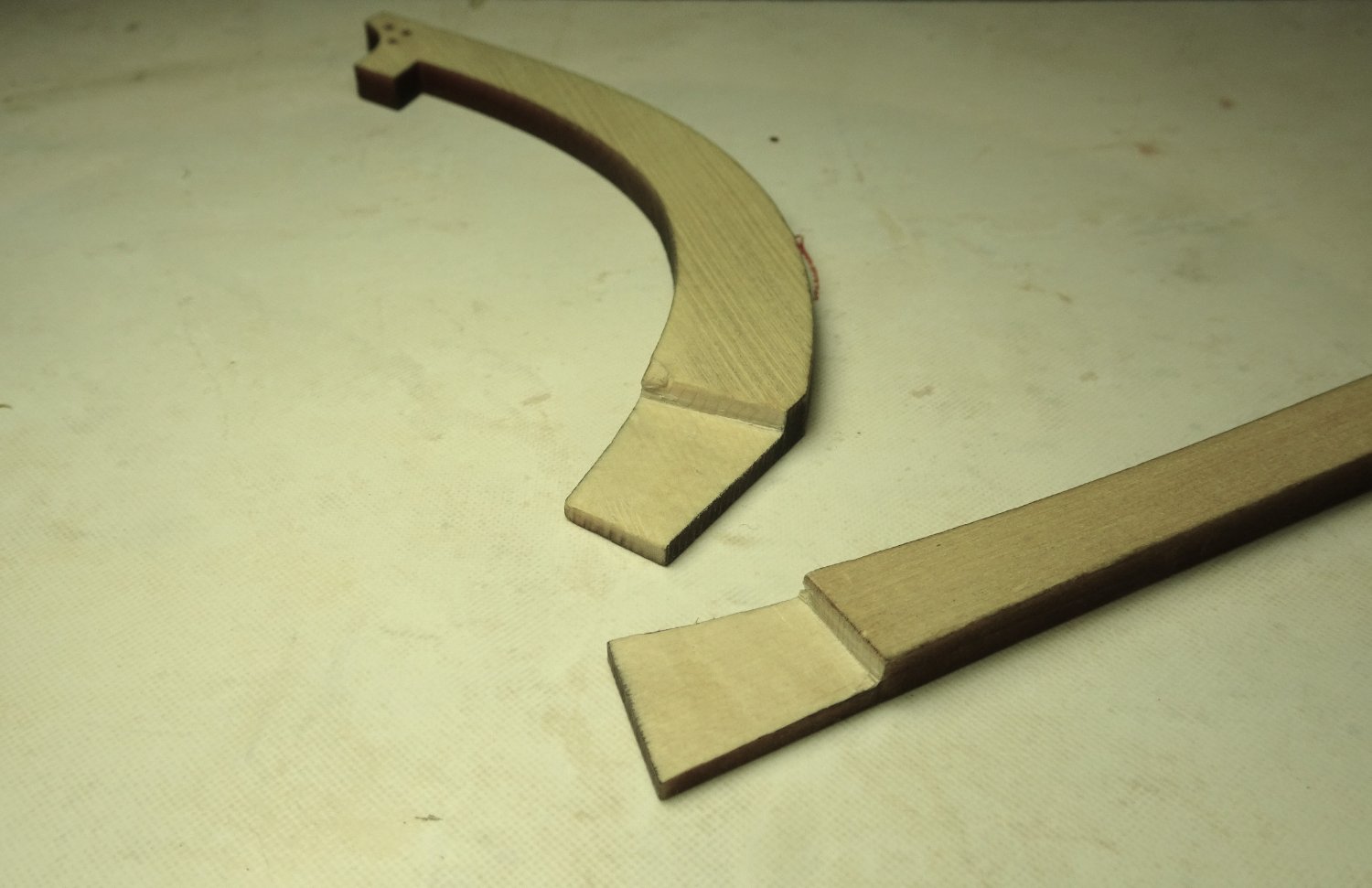
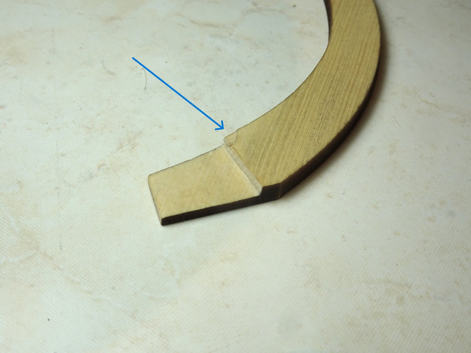
One annoyance was that a tiny corner piece of the stem broke away on the top side where it meets the lap joint rebate.
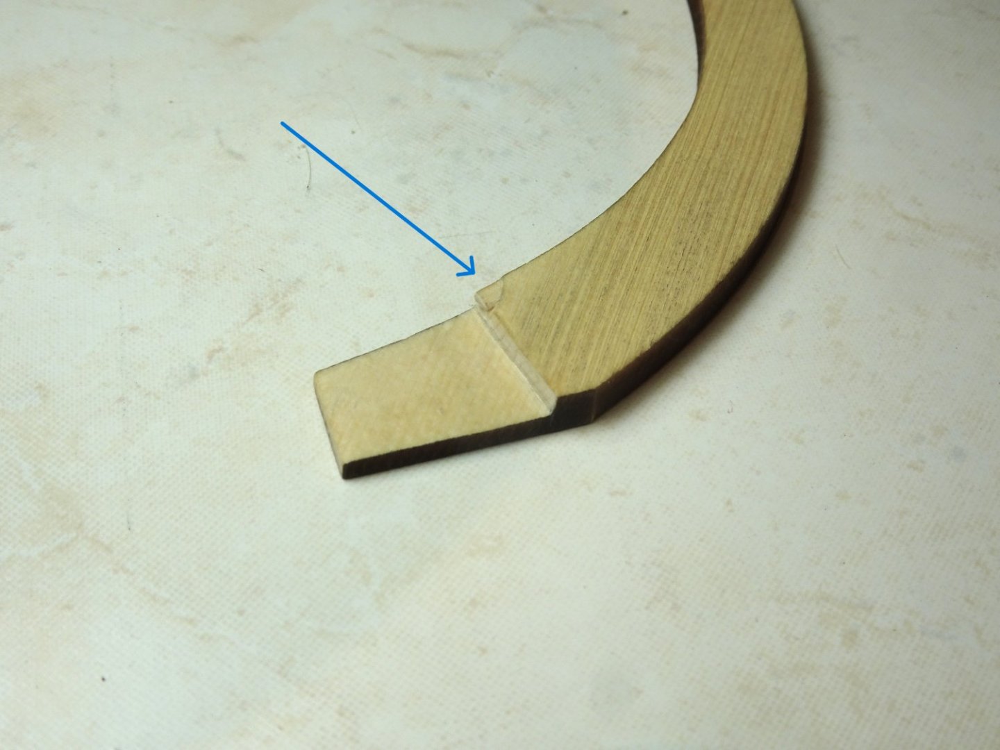
030
I added a small piece of timber and sanded flush, hopefully it won’t draw the eye.
The scarph joint arrangement keel is much easier to assemble, but despite Chuck’s assurances that the simple butt joint at the stern will hold, I am still nervous, but resisted the urge to dowel it.

037
I do the assembly on an old tile which provides a flat surface and can be kept clean.
045
038
The simplified version is shown here on the old build board for the Queen Anne Barge.

040

041
042
A paper template has been cut out to mark the nail positions on the lap joints.
B.E.
16/01/2023
- Beef Wellington, James G, glbarlow and 8 others
-
11
-
I have been harbouring this offering from Syren for nearly four years, so it’s time to come out from beneath my bench.
My kit dates from 2019 and this will be my next project, and the third from the Syren SMC. Having thoroughly enjoyed both Cheerful and The Queen Anne Barge I am very much looking forward to the Longboat.
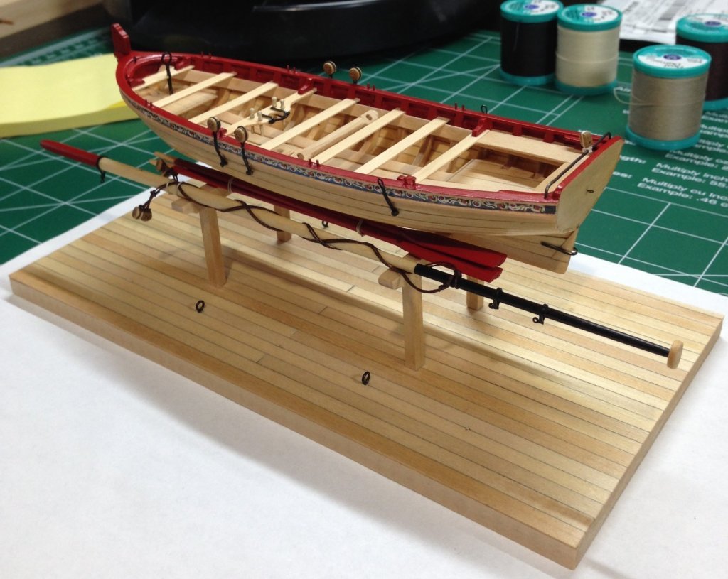
I am not completely unfamiliar with the Longboat style as I completed the MS 1:48 scale version (also a Chuck Passaro design) back in 2017.

2780
I enjoyed that build and it makes a nice-looking model, but the ½” version is a significant step up in terms of accuracy, materials, and quality.
I am a late arrival to the Medway Longboat party, and I doubt I can add anything to the wealth of experience as recorded in the public group forum for Medway, not only Chuck’s build, but also from others whose work I have long admired.
I am fortunate to have all this to hopefully smooth my way along.
I will spend some time reading thro’ the logs before I begin.
B.E.
08/01/23
-


36 Foot Admirals Barge by Blue Ensign – FINISHED - Vanguard Models – 1:64 scale
in - Kit build logs for subjects built from 1751 - 1800
Posted
Having built both Fifie and Zulu, I would say that the Zulu is slightly more tricky to plank than the Fifie, but both represent excellent starter builds, but also provide the opportunity for enhancement.
I don't think you would be disappointed by either.
B.E.