
.JPG.ca33079f5815b861e67b9c2cccd37982.JPG)

Blue Ensign
-
Posts
4,286 -
Joined
-
Last visited
Content Type
Profiles
Forums
Gallery
Events
Posts posted by Blue Ensign
-
-
-
-
Thanks Kevin and Nipper.👍
@ Kevin, - I think the jury is still out on that one, I'm always edgy until the first planking is done.
@ Nipper - Kind of you to say so, it's not that time -consuming, there's only so much concentrated effort I can handle at a time. I take quick photos as I go along, write up the post on a word doc, and copy and paste to MSW. Doing the log is a nice break from actual building.
My motives are not entirely altruistic, I use my own logs as crutch to my memory. I'm at the stage of life when I think how did I do that last time - I've just looked back on Sphinx to see what I did with the Garboard.🤔
Cheers,
B.E.
- Knocklouder, SIDEWAYS SAM, glbarlow and 5 others
-
 8
8
-
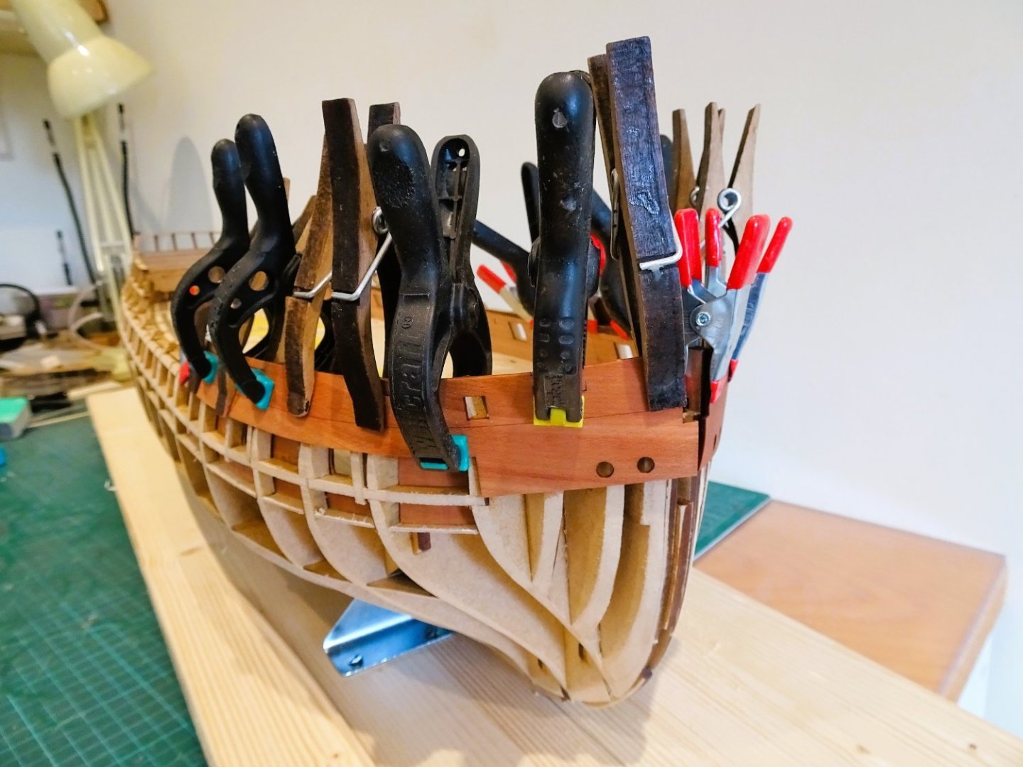
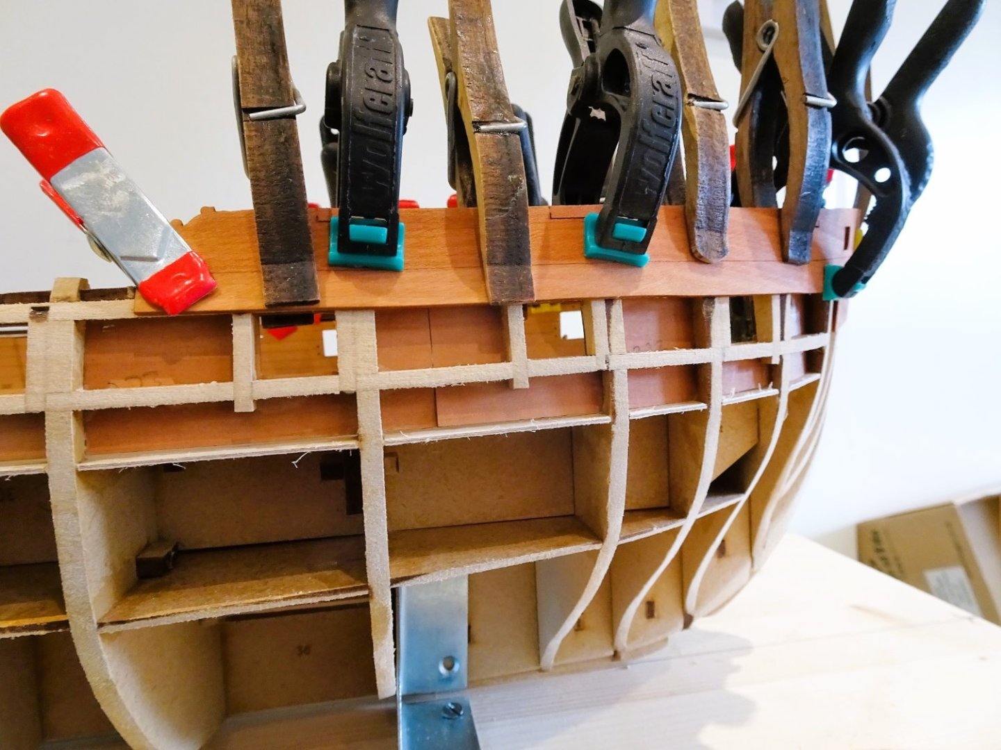
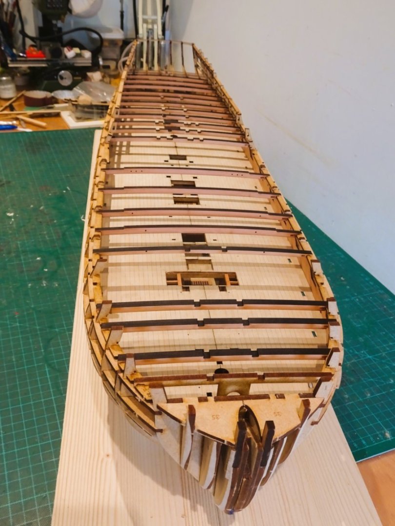
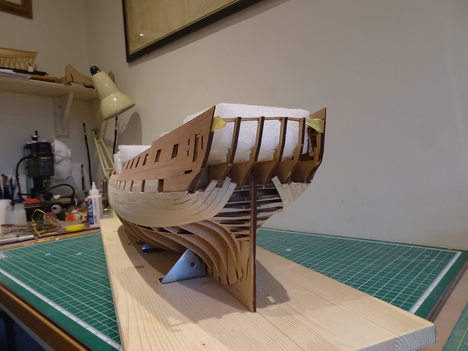
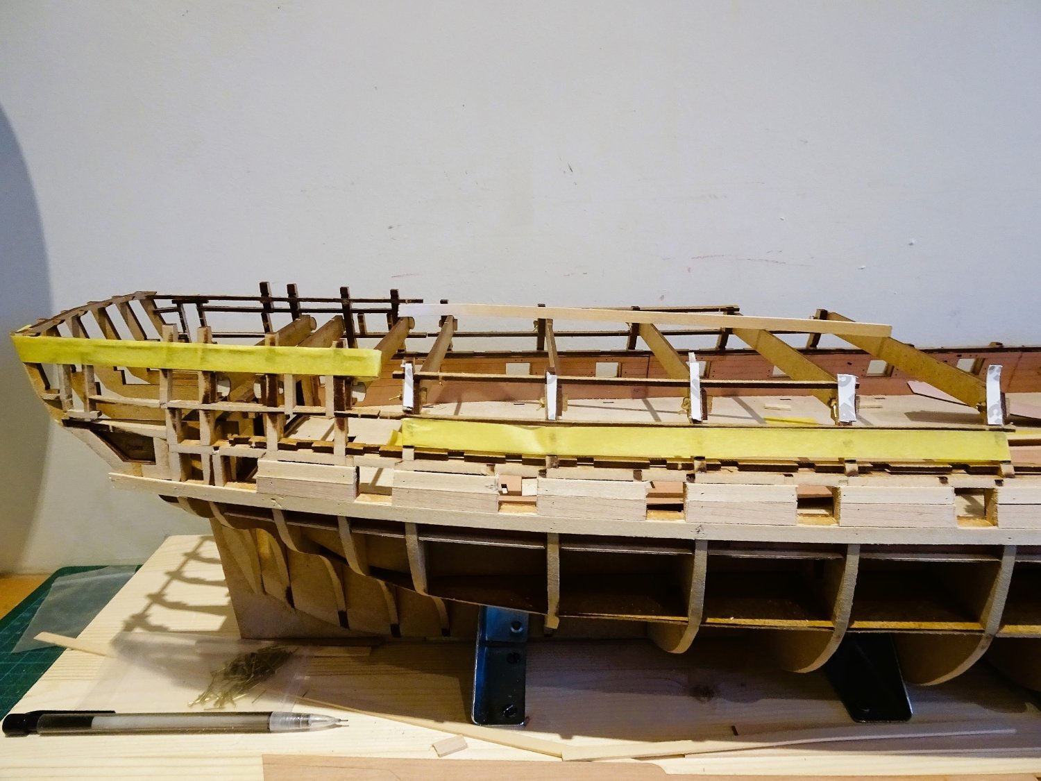
Post Eighteen
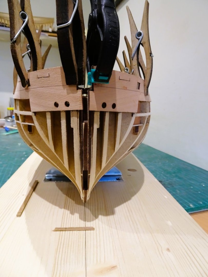
Planking continues – Garboard strake
This is the point where I need to fit the Garboard plank to determine the planking requirements for the remaining area.
Garboards can be tricky planks to fit in terms of shape and where to end, and they always cause me some head scratching.
Some may think why bother, this is only the first planking that is to be covered, and perhaps even covered again by coppering.
For me it’s about keeping options open.
If the second planking is good enough not to be covered, then fitting a garboard on the first planking run will give a valuable insight for shape and position on the second show planking.
It does mean that extra planking widths will be required.
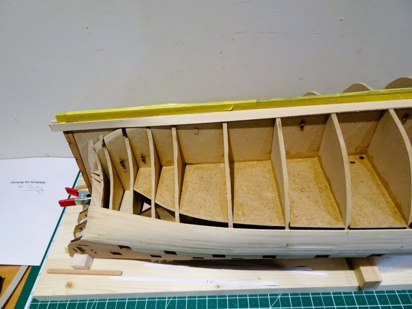
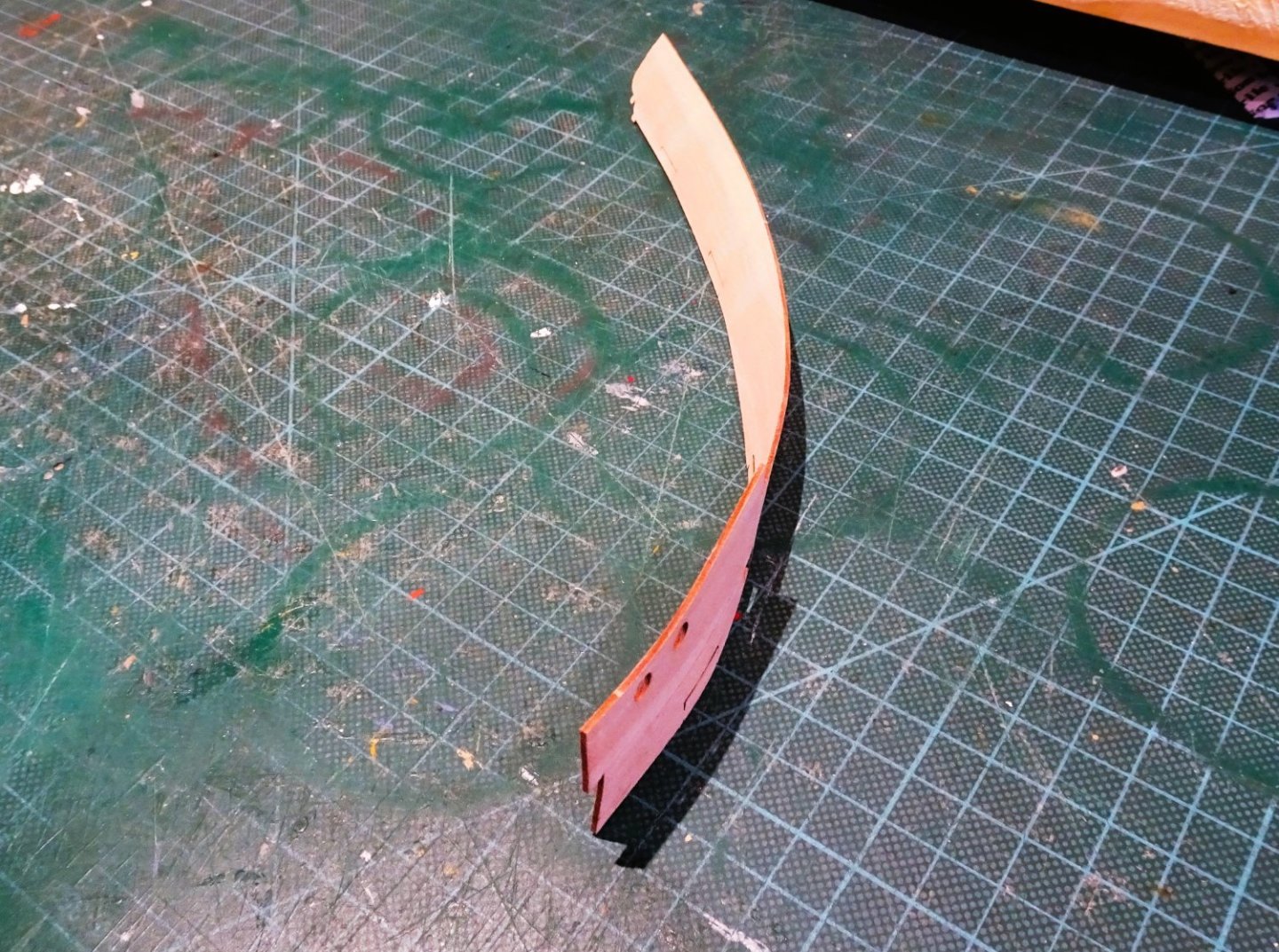
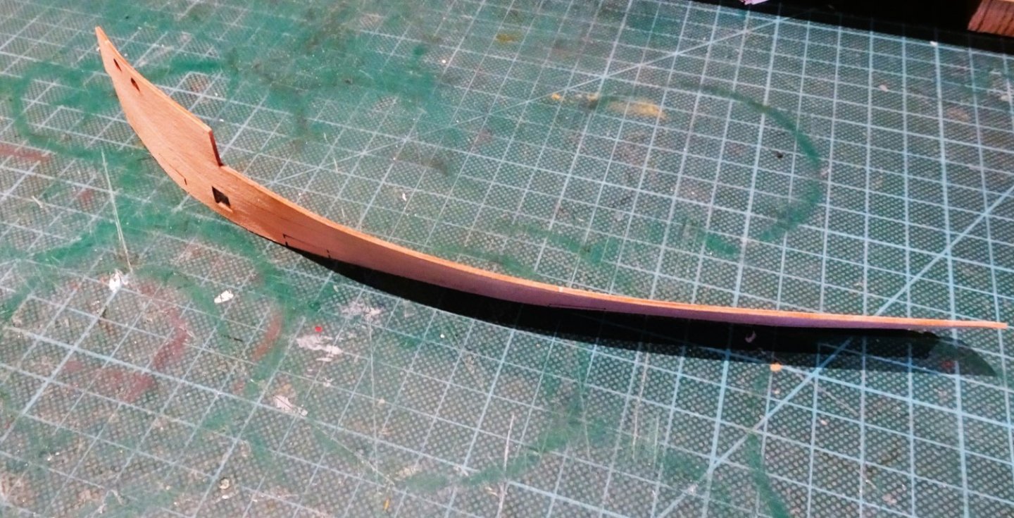
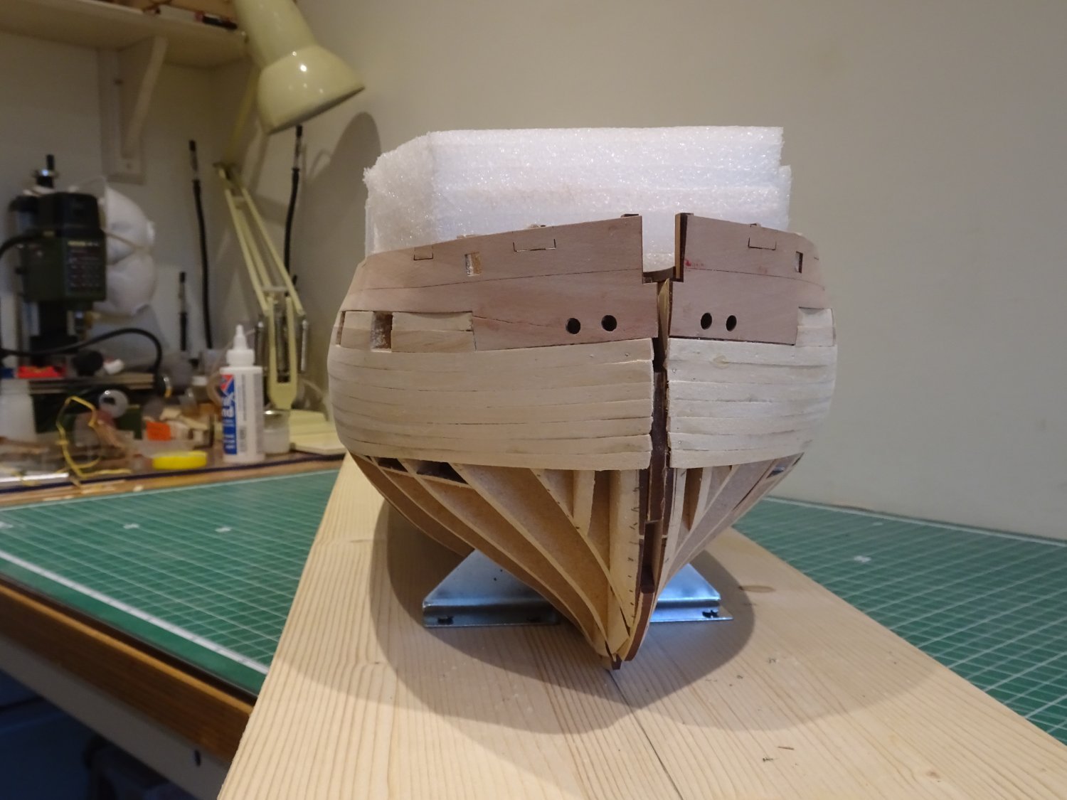
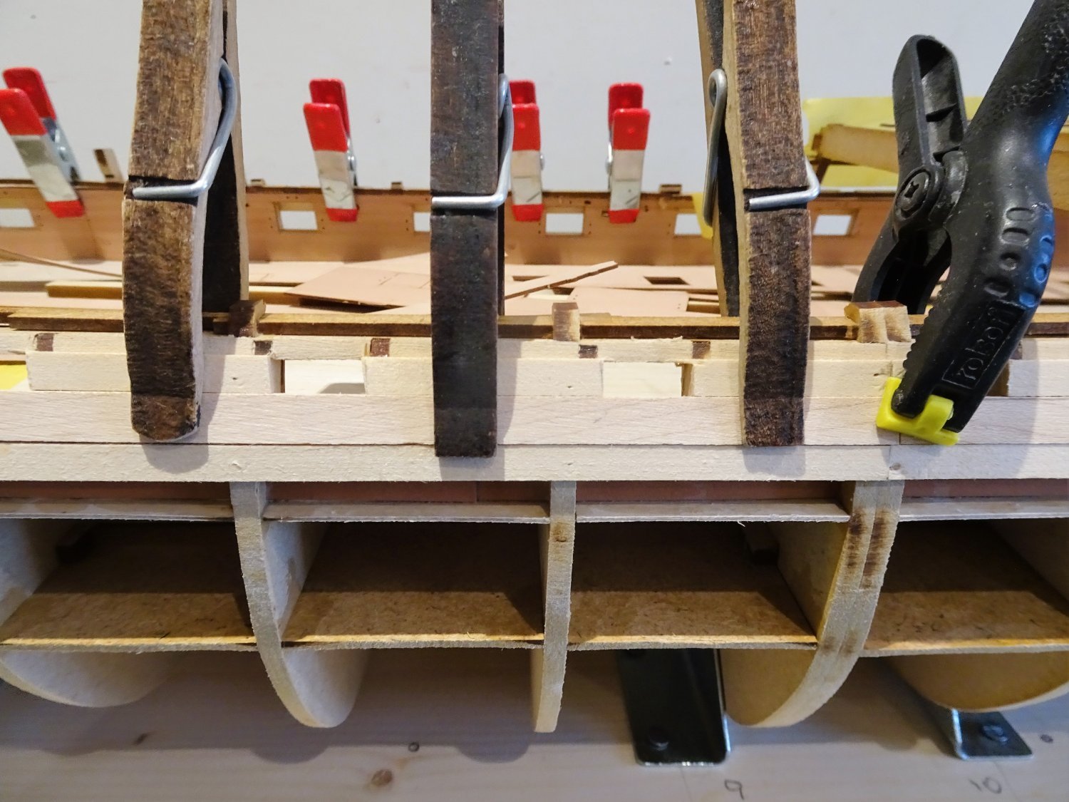
I am using a 10mm wide board, but I need to temporarily fit the keel and stem pieces to properly work out the shape and termination point at the bow.
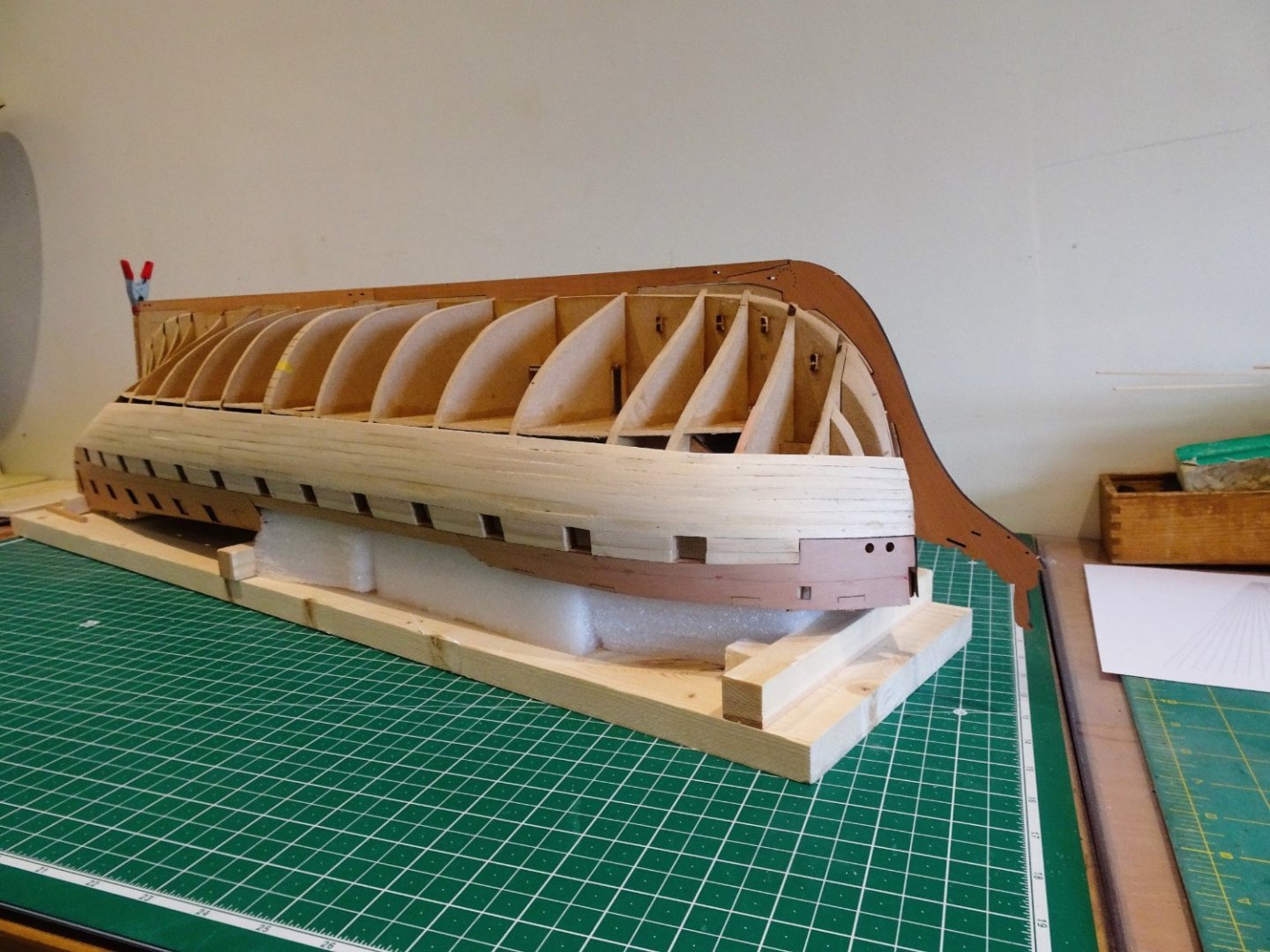 0685
0685
A real pleasure to get the keel elements in place even if only for a while. Beautifully cut, a perfect fit, and great to have a quality wood finish for the parts rather than mdf.
Perversely my next move is to cut an mdf stem piece against which to form the Garboard. I can’t risk the proper stem during the working process.
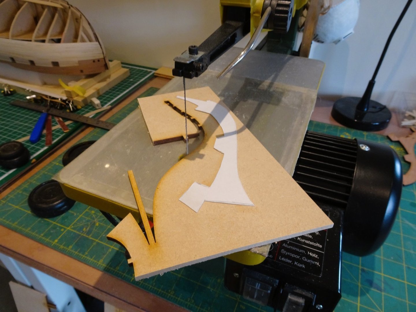
0689
Time to fire up the scroll saw.
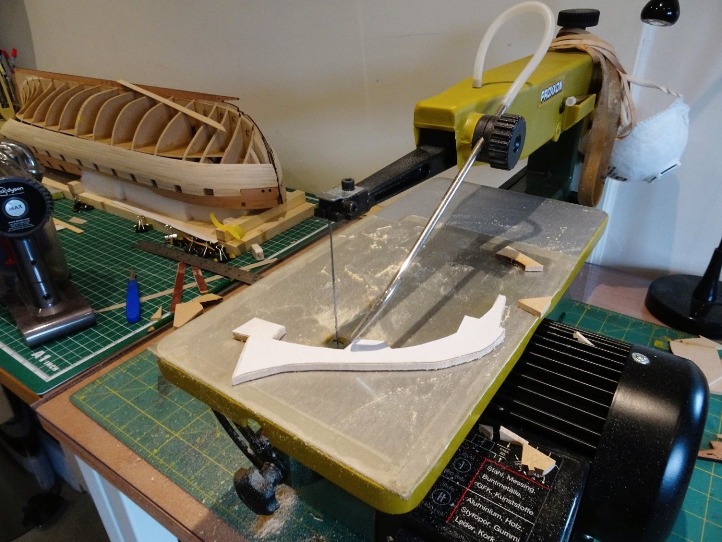
0692
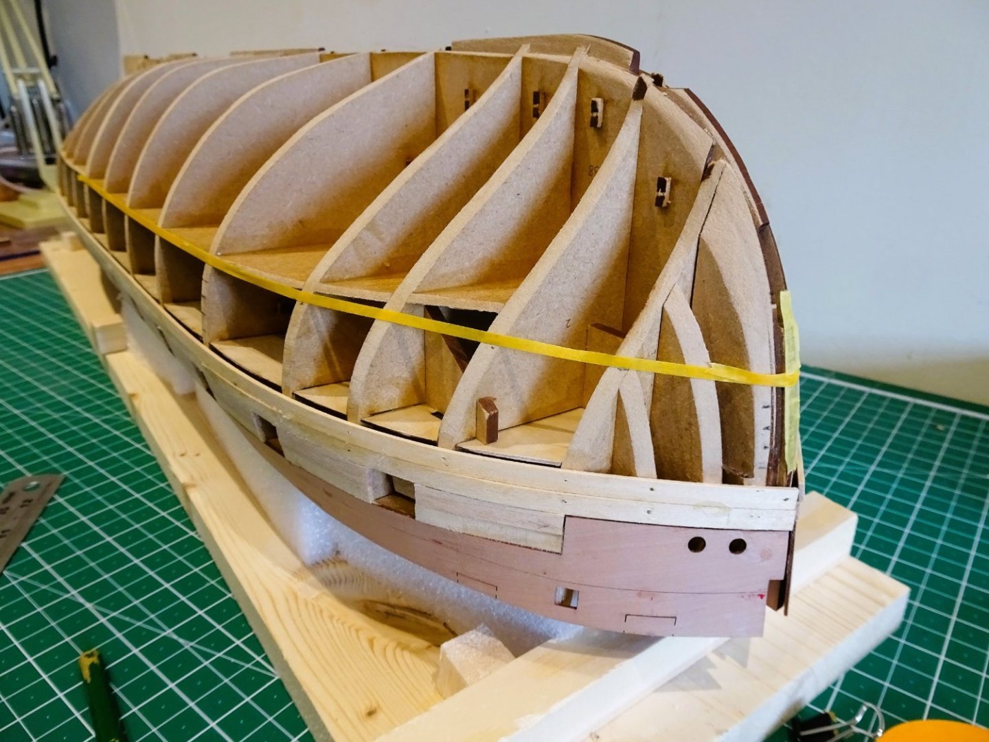
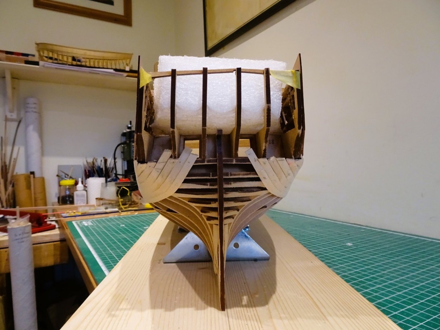
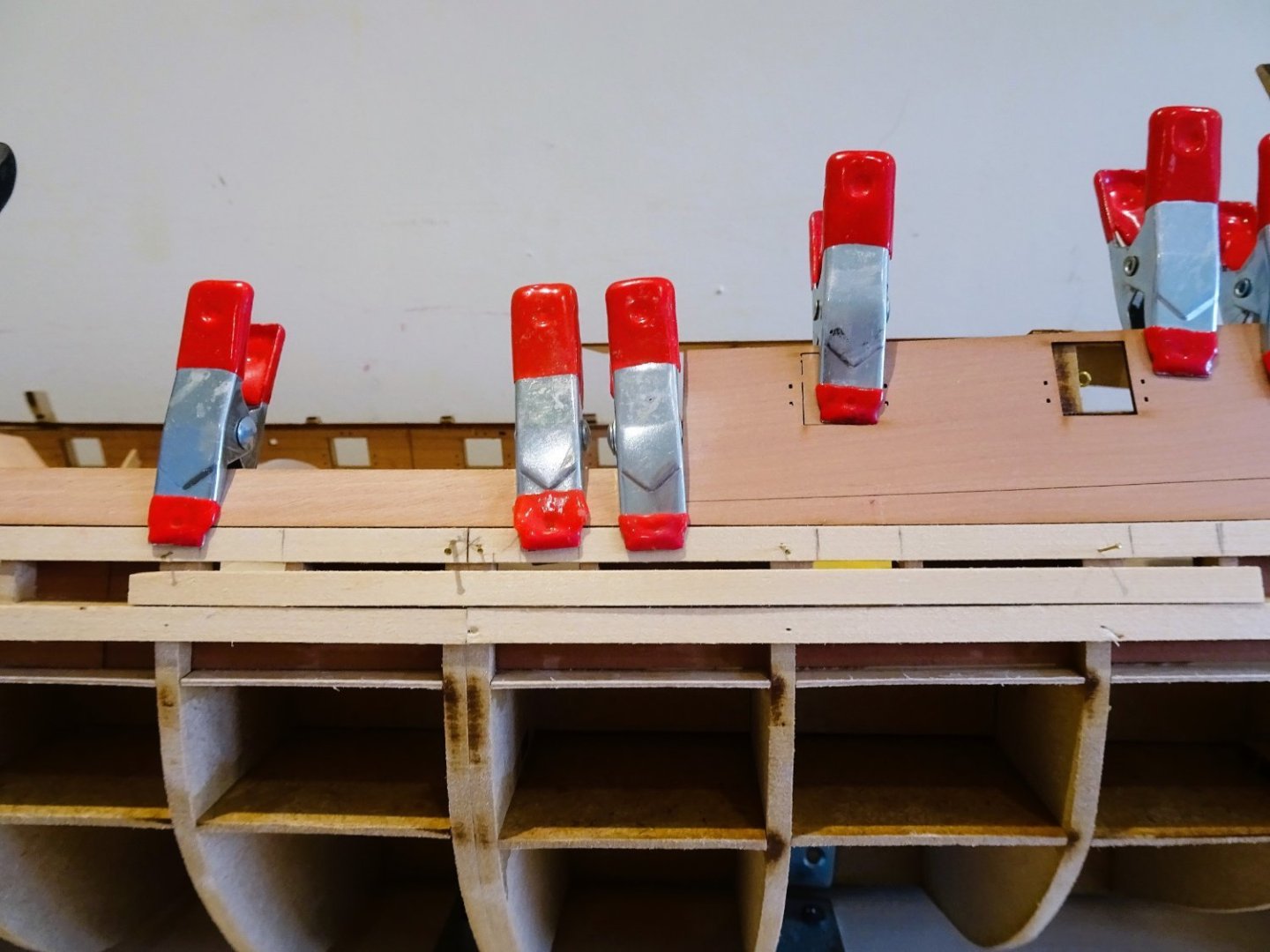
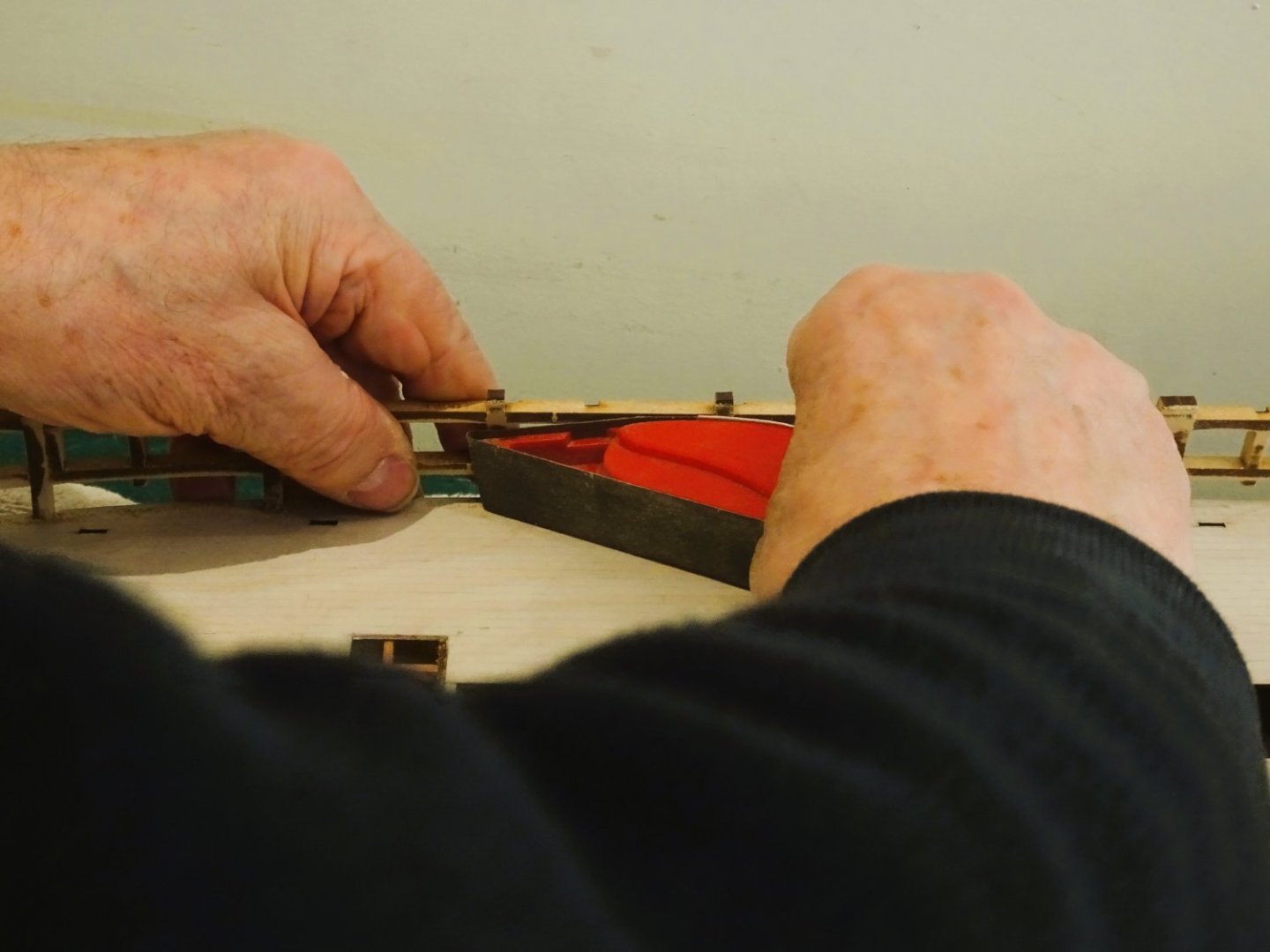
I don’t see any reason not to leave the keel pieces in situ at this stage, as the Garboard is the only plank that abuts, and it will assist the fitting.

0693
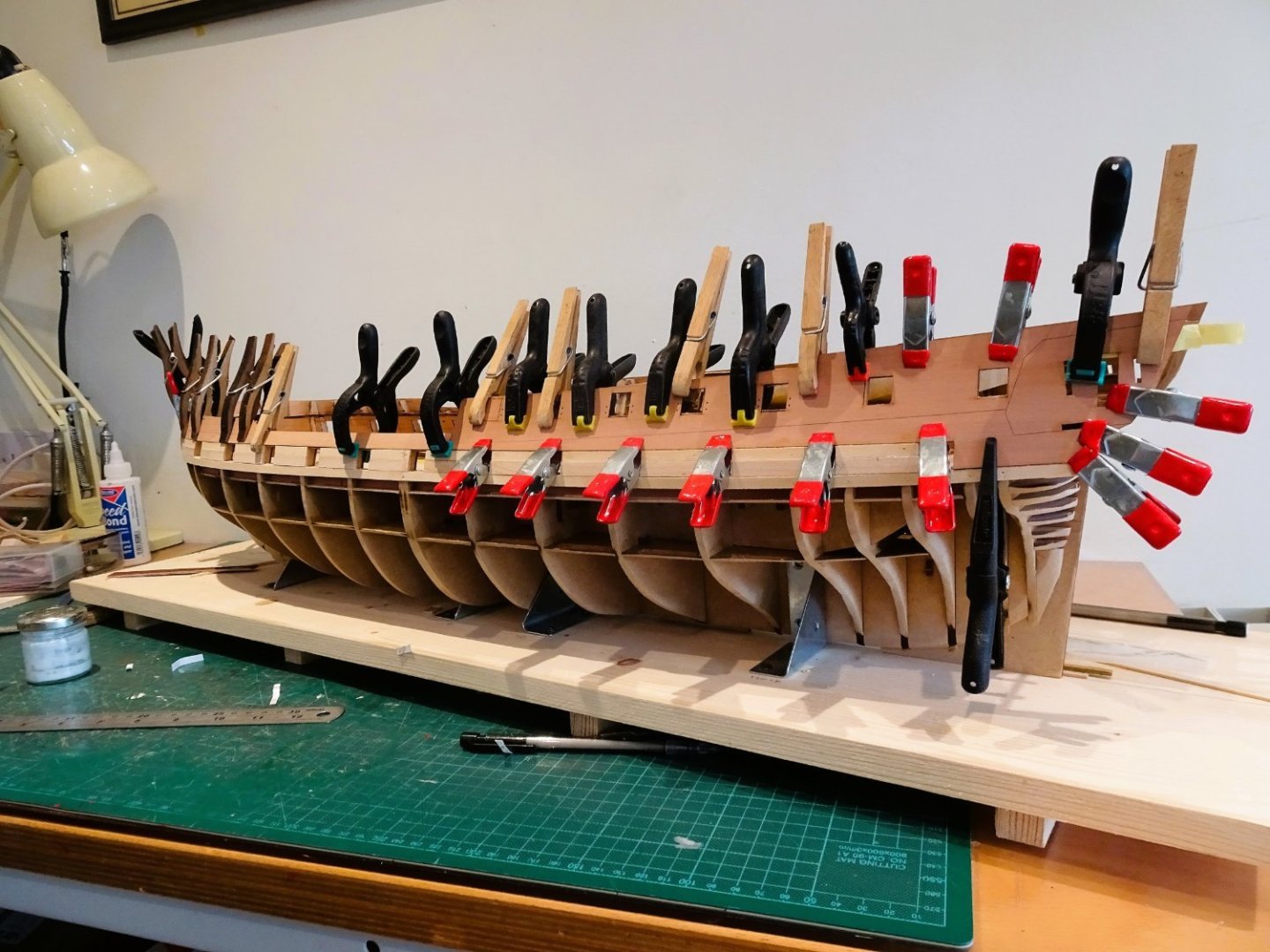
A lot of time is spent tweaking the plank to gauge the right position. I’m never fully confident that I’ve got it right, but whatever the outcome doing it on the first layer will show the way for the second planking.
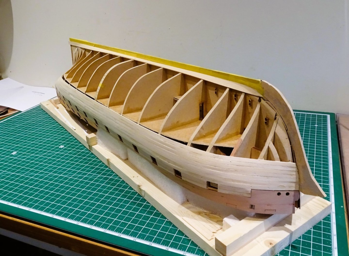
0695
I take the pre-caution of taping the keel, in part to avoid the planks getting glued to the keel at this point.
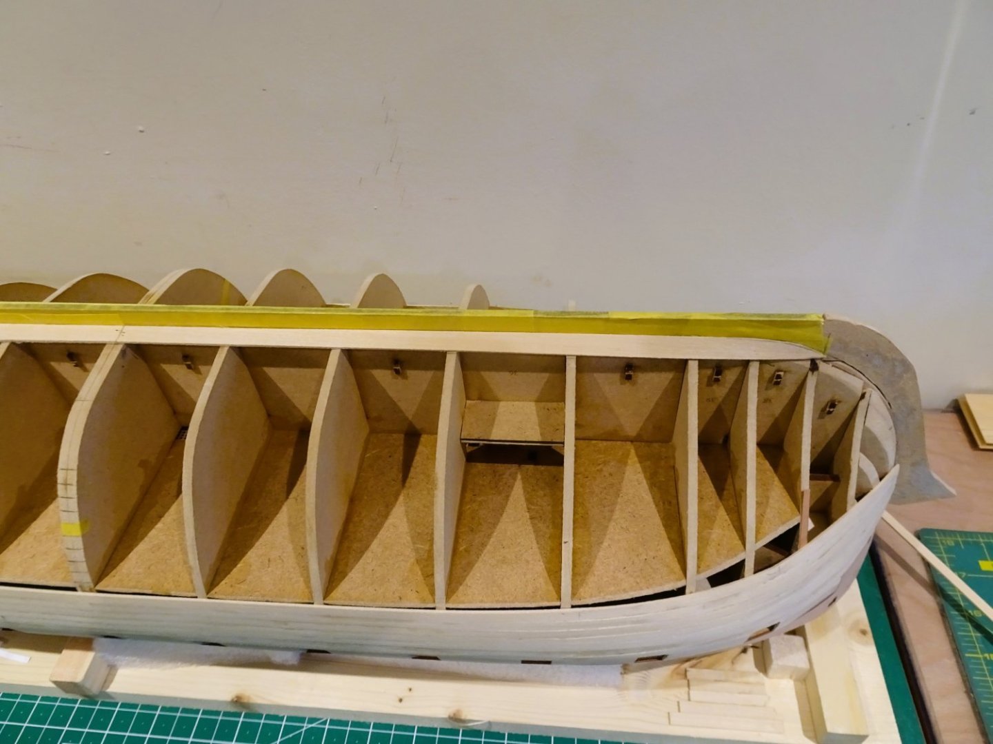
0698
0699
0700

0701
0702
I can now begin the next phase of planking.
B.E.
07/04/2023
-
Thank you, Guys,
@ Jason and Glenn – I’m glad I’m not alone, I can’t see any reason not to apply even a rudimentary stagger to the butt joints; as you say Glenn it’s all part of a useful practice run for the second planking.
@ Allan – I’ve already had the Garboard in place to mark the gap at the central point.

0663
I am using a 10mm wide board, but I need to temporarily fit the keel and stem pieces to properly work out the shape and termination.
This will be my next job.
Regards,
B.E.
- DelF, Kevin, realworkingsailor and 10 others
-
13
-
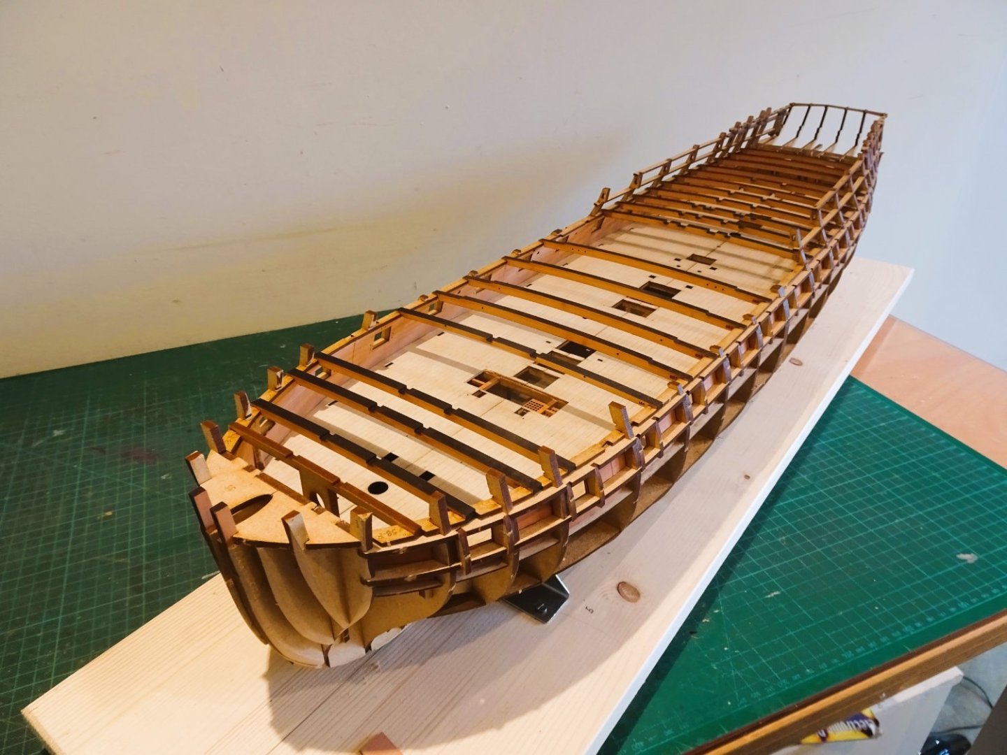
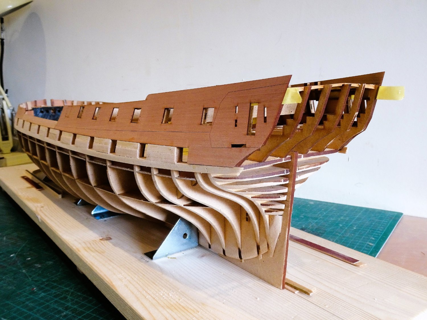
Post Seventeen
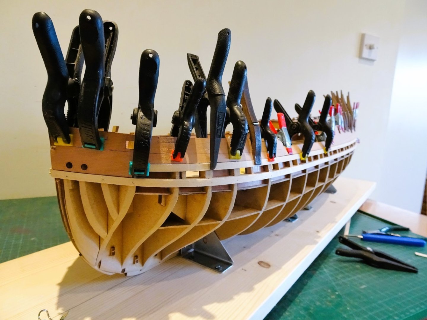
Hull planking.
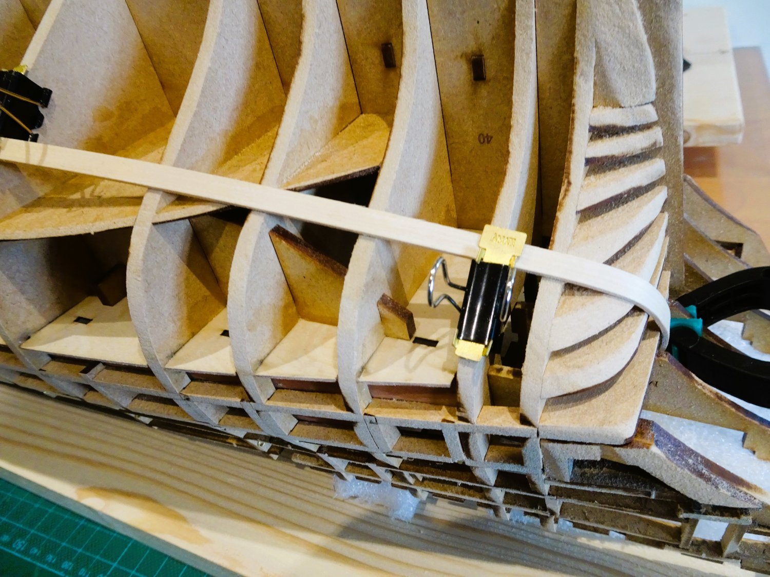
On my builds I have always tried to follow the procedure I will use for the show finish. Perhaps with a little less adherence to a full tick strip method, but still utilising tapering, edge bending, and spiling as a method to achieve a reasonable planking job.
This gives me an insight into how the timbers will flow when I get down to the ‘proper’ job using show timbers.
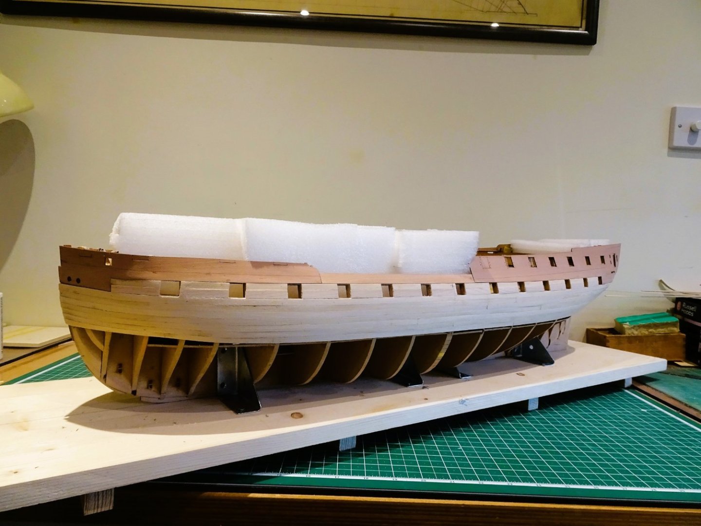
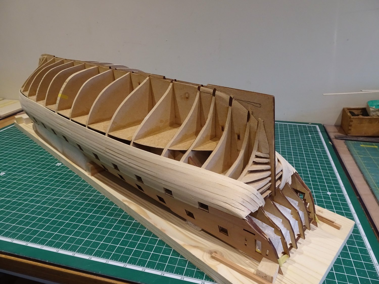
The planking will be done with the hull inverted, this gives me better control.
0658
I opted to plank a first section down to the lower deck level which involves five strakes.
I used tape to indicate the line at the bow.
Starting at the Bow and using a tick strip I have calculated that very little taper is required – less than 1mm starting at Bulkhead four.
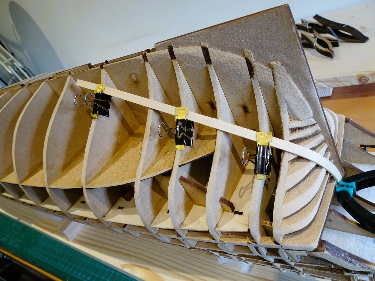
Joining all planks at the central bulkhead is a practical approach, but the look of it offends my eye even tho’ this is only the first layer. We all have our foibles, I guess.
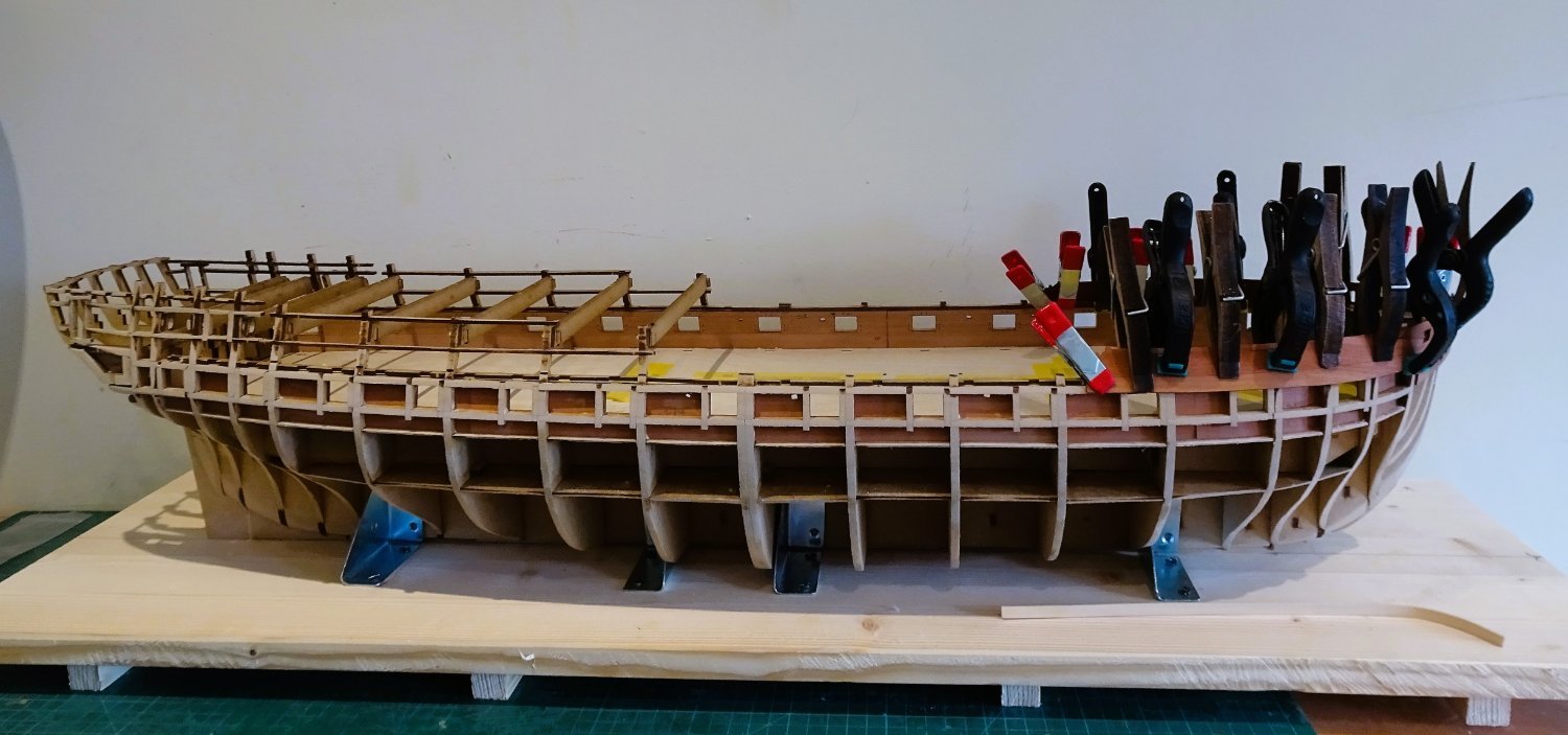
I work side and side about, strake by strake.
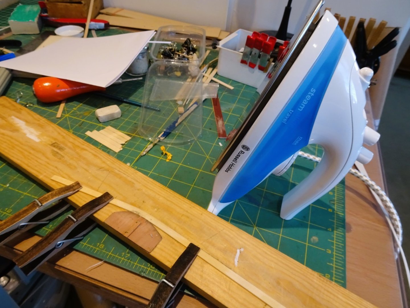
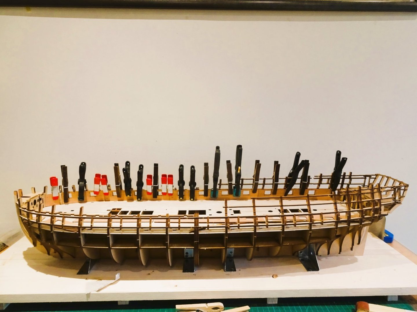
I opted to fit a long forward plank, and a shorter aft plank cut from a longer strip to facilitate the bending.
0655
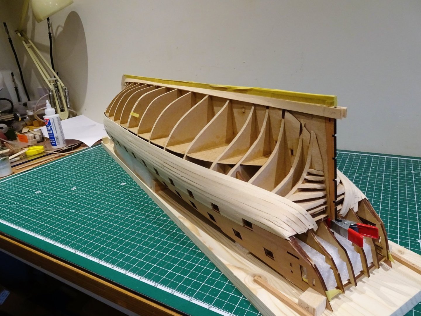
The aft plank is soaked, and the bend at the aft end is formed by heat.

0657
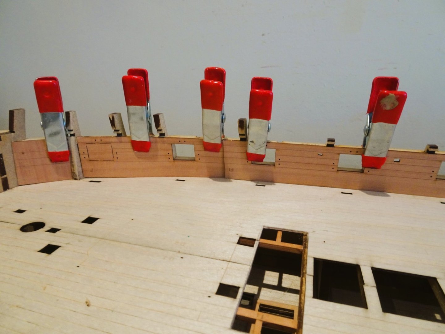
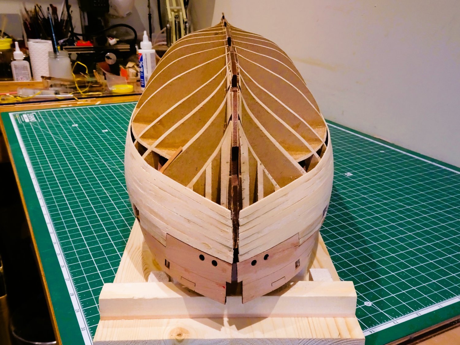
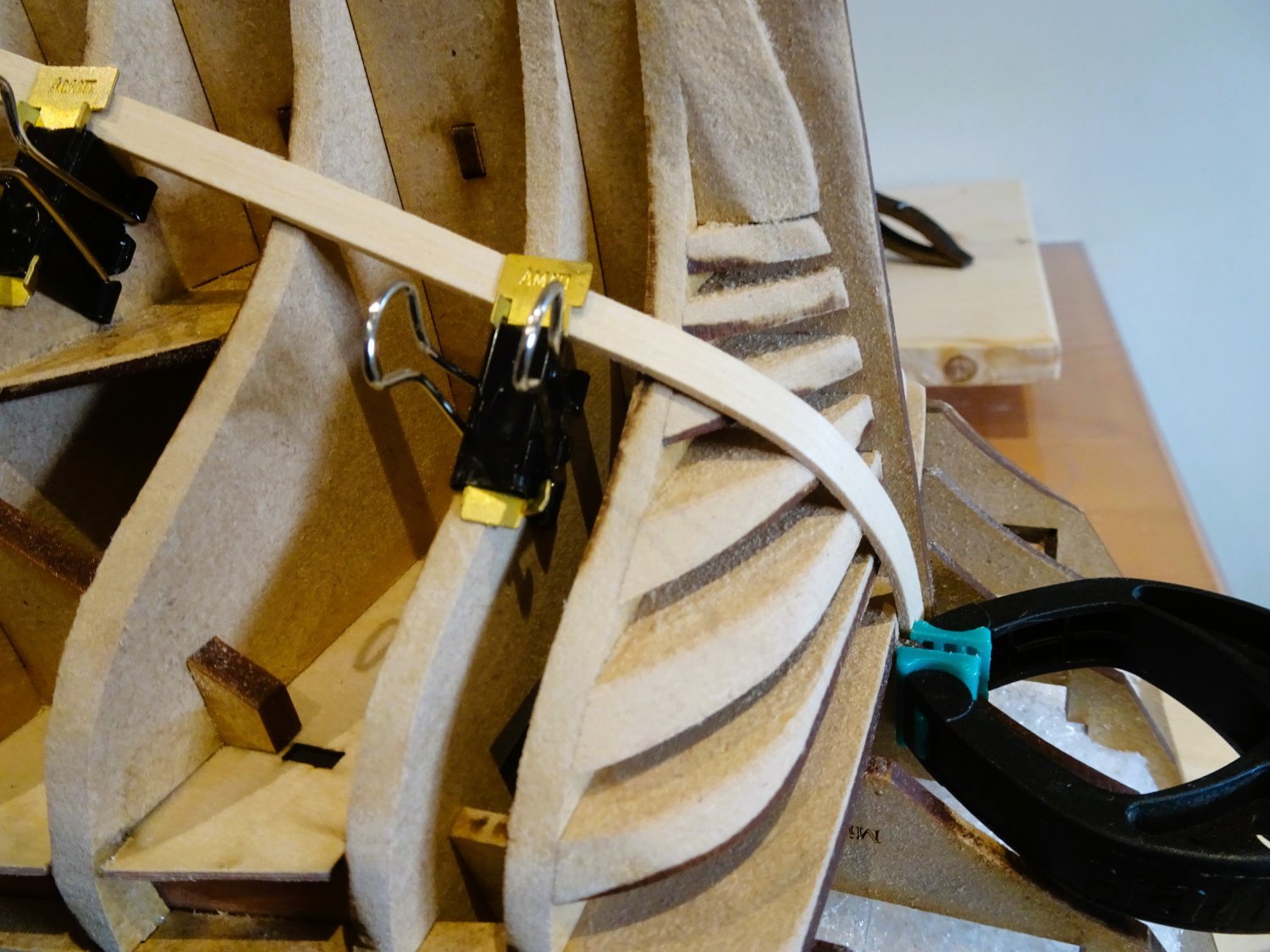
The bends up to the lower transom are fairly easy to form if sufficient soaking time is allowed.

0667
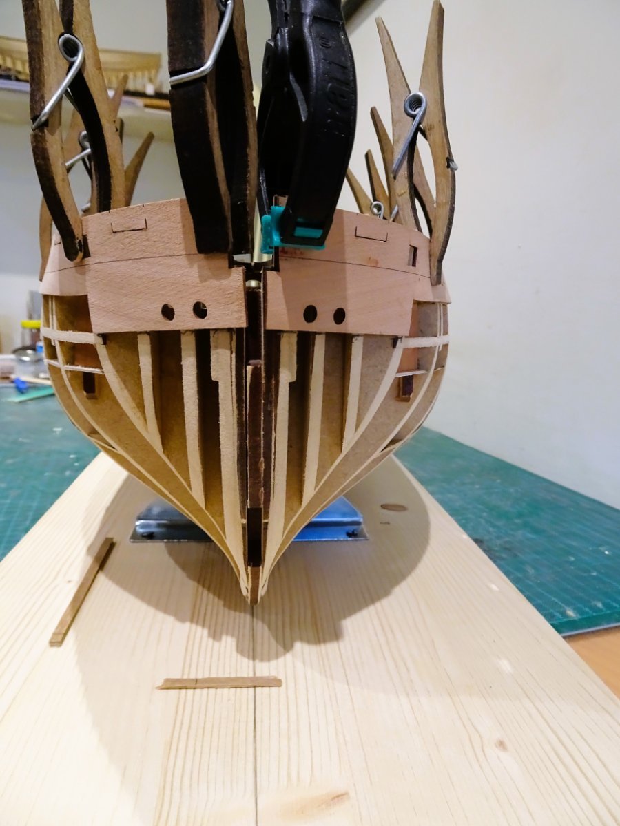
Once formed I temporarily pin them in place and heat blast them.
0660
At the bow end the lower two strakes required a little edge bending around bulkheads two and four to achieve the fit.
0664

0668

0671
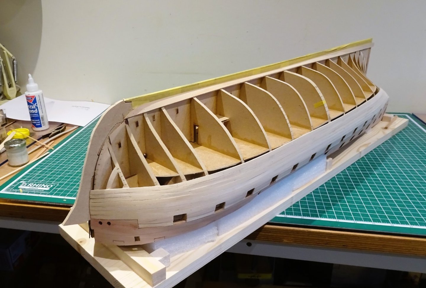
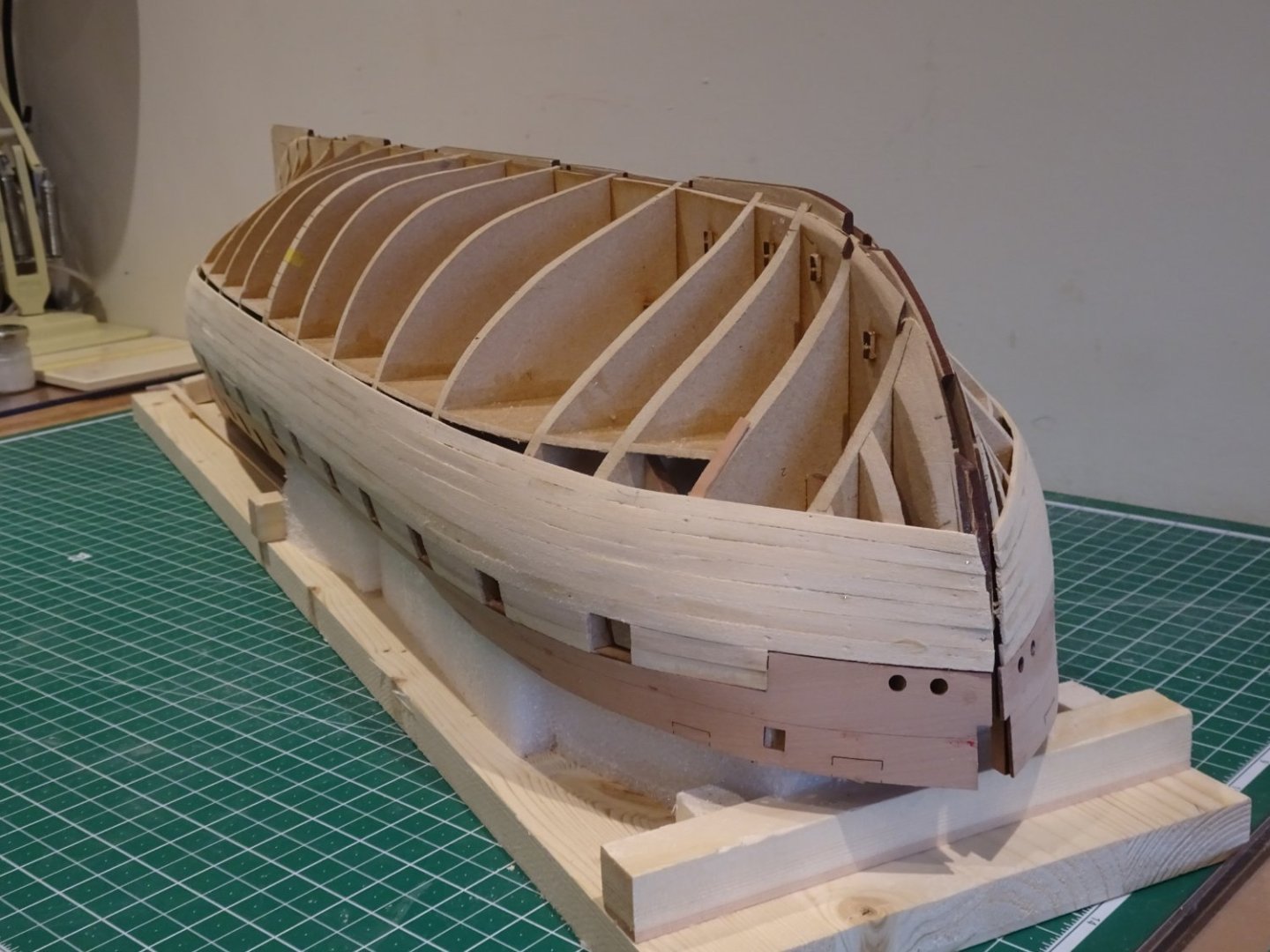
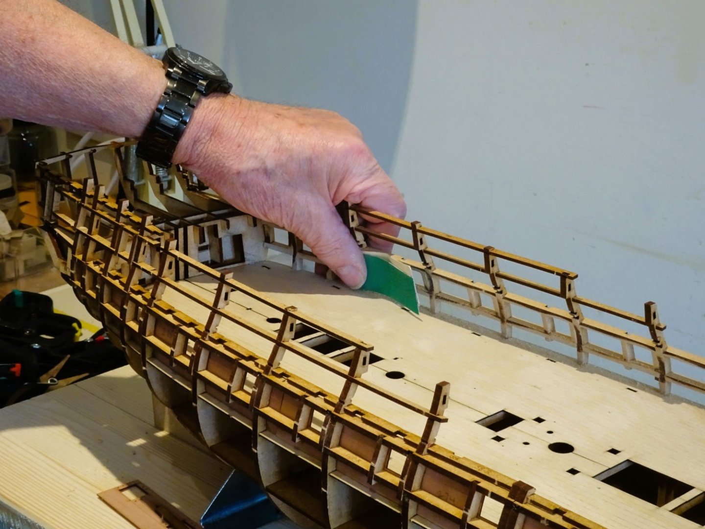
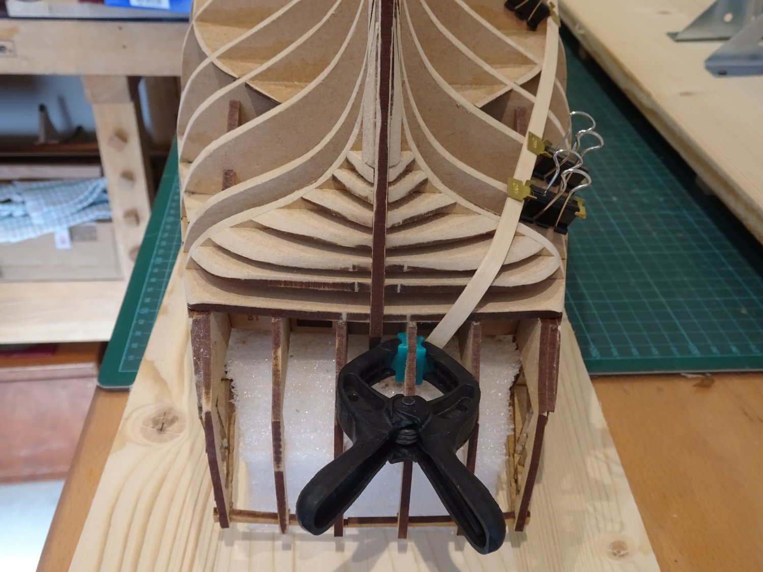
Still in very much a rough state which the sanding should take care of.

0677

0680
0681
0684
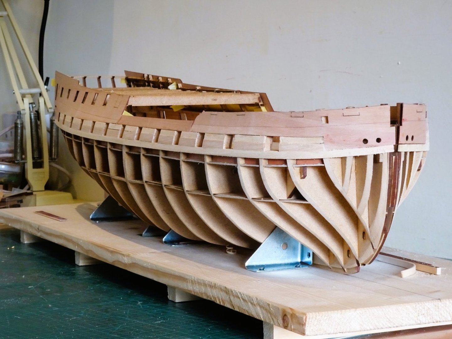
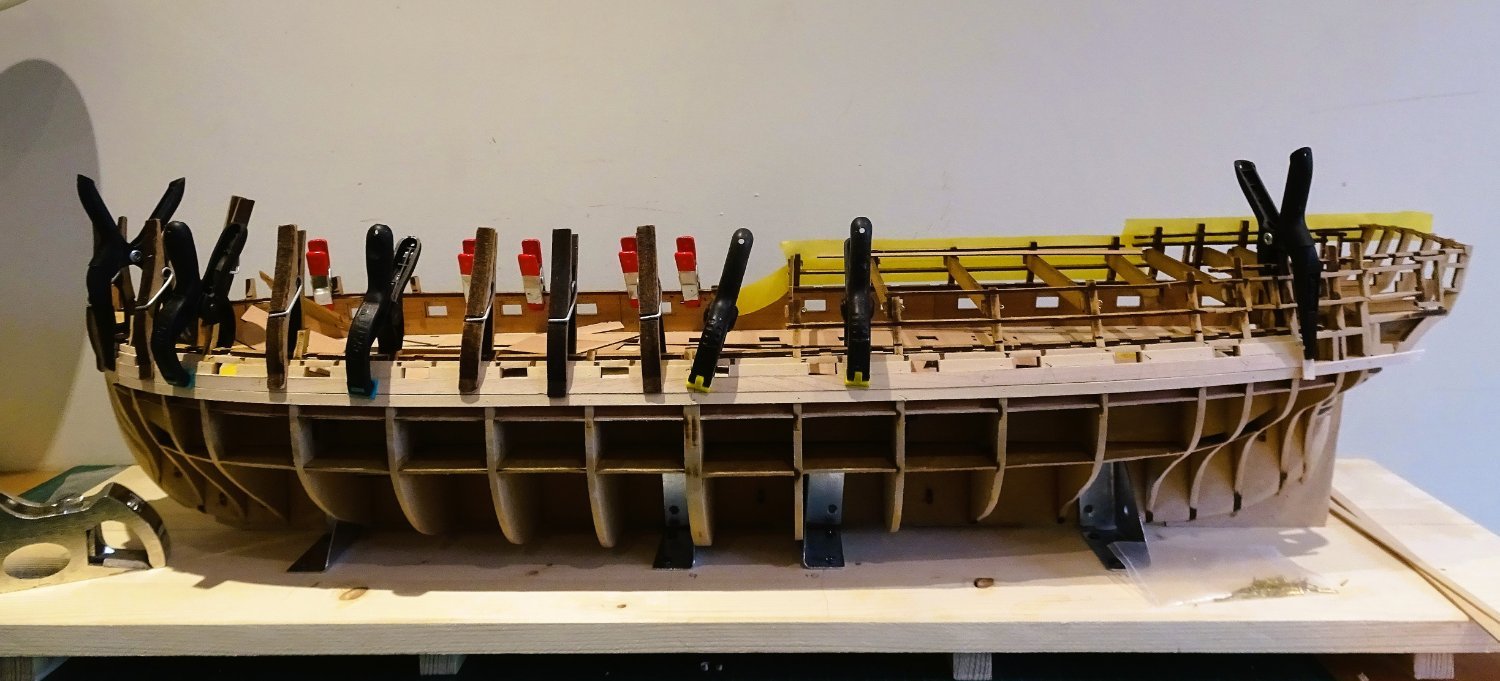
I like to check the planking run with the hull the right way up, looking ok so far I think.
B.E.
05/04/2023
-
Good fix on the deck Derek, that will blend in beautifully. 👍
B.E.
- SIDEWAYS SAM, mtaylor and DelF
-
2
-
 1
1
-
Beautiful work Rusty, she is a very fine looking 'Winnie'
Your care and attention have paid dividends as is so clearly evident.
Regards,
B.E.
- Rustyj, James G and FrankWouts
-
3
-
Well done James, and hopefully some beneficial results for Vanguard. 👍
B.E.
- Rik Thistle, Mr Whippy, thibaultron and 3 others
-
6
-
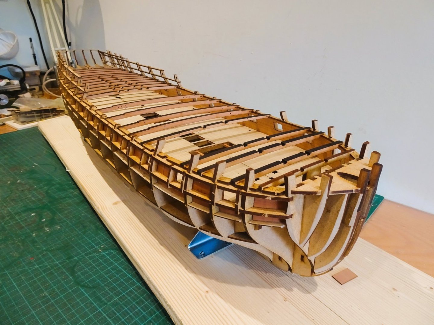
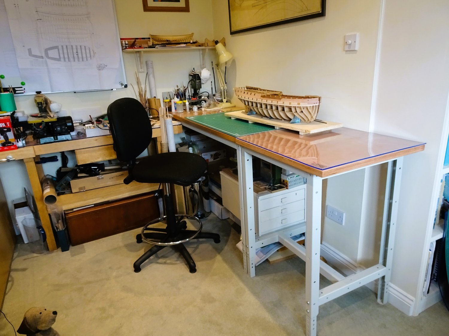
Post Sixteen
A workshop enhancement
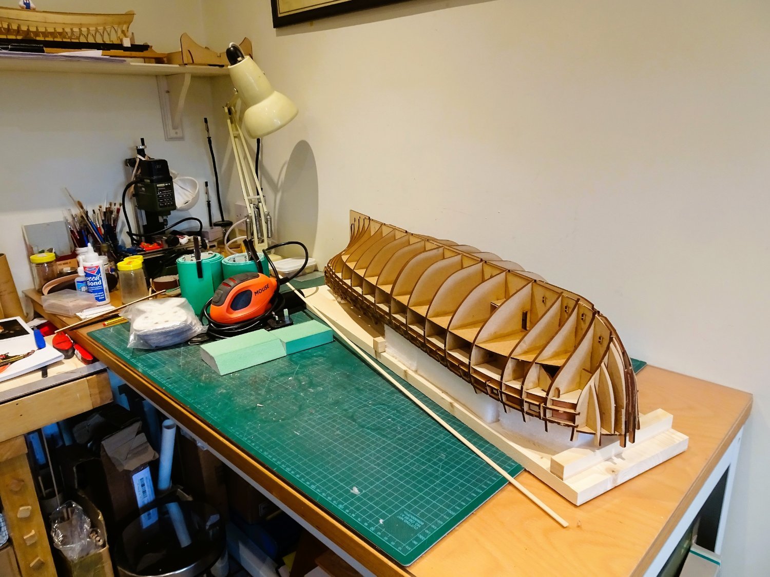
I have been feeling cramped of late as I try to manoeuvre the ‘Indy’ beast around, with only 600mm of depth available.
My latest acquisition is this work stand.
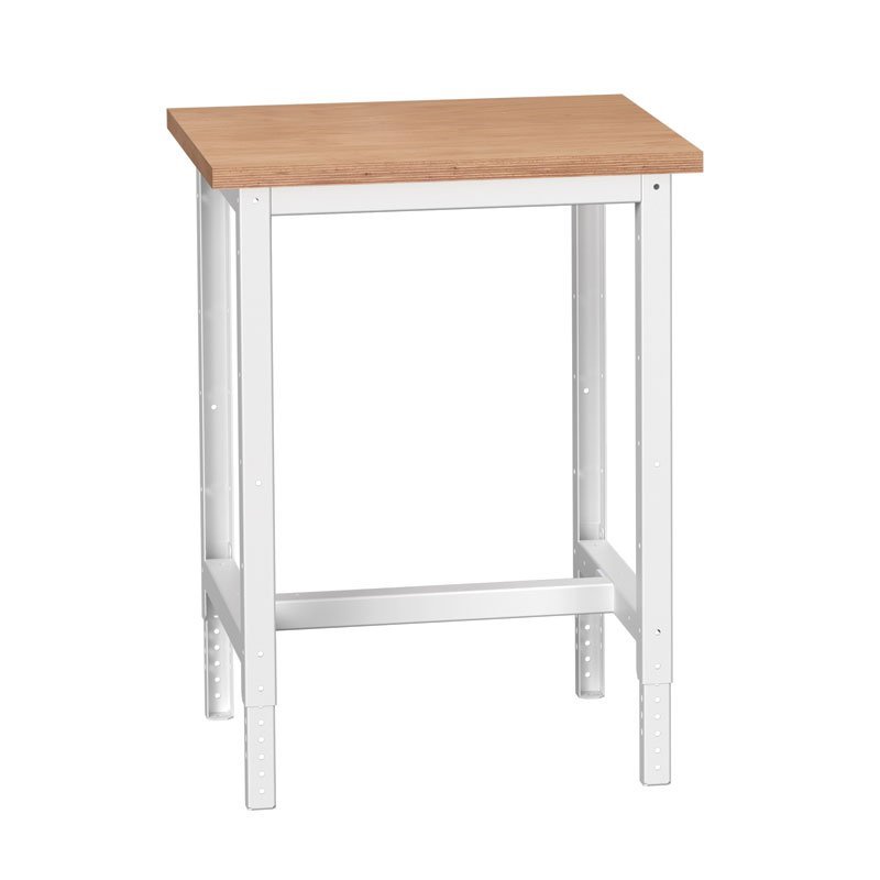
Bott work stand.
It is in the same range as my work bench and equal in terms of depth and (adj) height but being portable I can re-position it to give me either more length or depth to suit.
0647
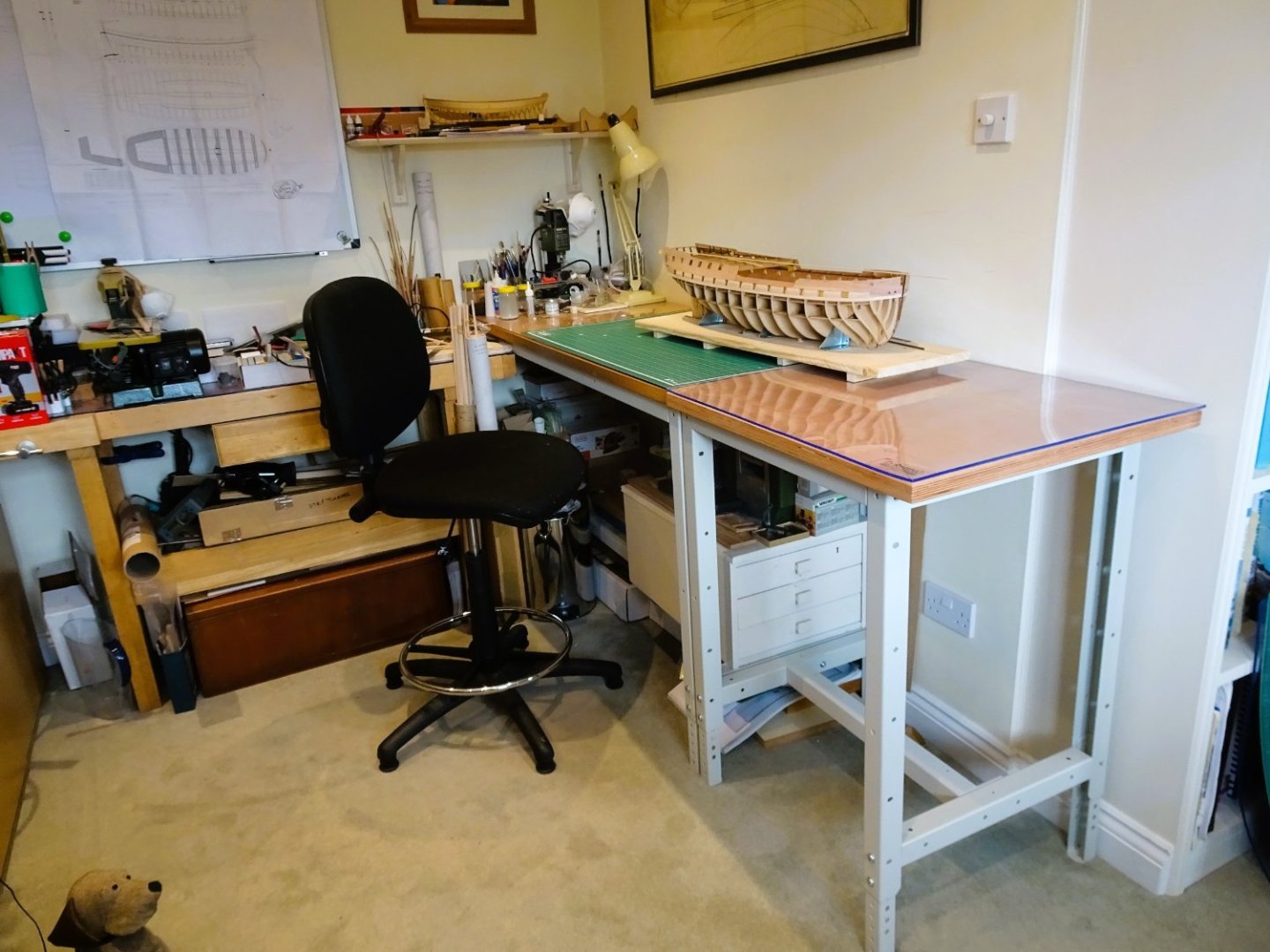
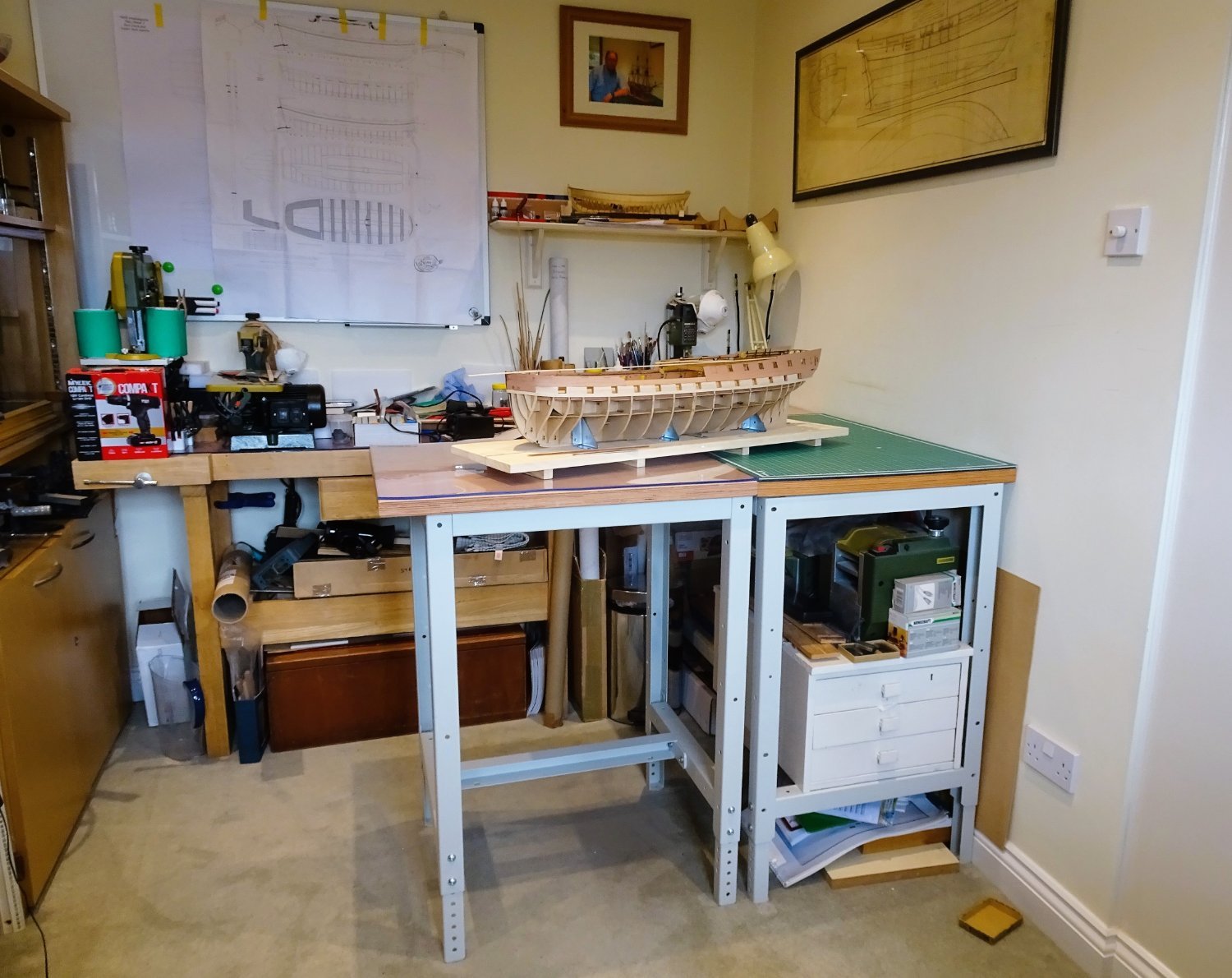
In a straight line I now have seven foot+ length to play with.

0649
This ‘L’ shaped configuration is likely to prove even more useful. It allows me to walk around the model and provides more space for turning.
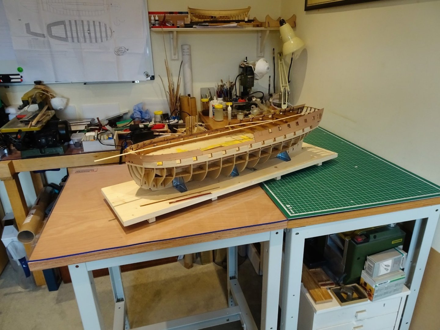
0651
I am hoping it will remove the frustration of working in a space a tad too small to freely manoeuvre the hull without risking bashing it on the wall.
A small price to pay for the added convenience.
B.E
01/04/2023
-
Thank you Gus, Glenn, and Alistair, your interest is much appreciated, as is those who have 'liked' the posts.
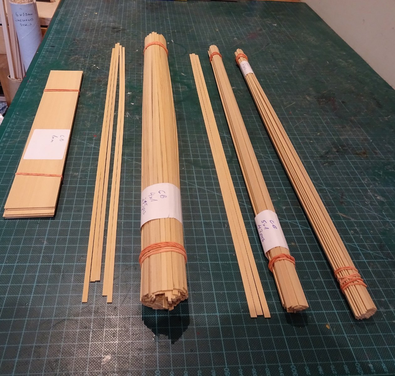
Post Fifteen
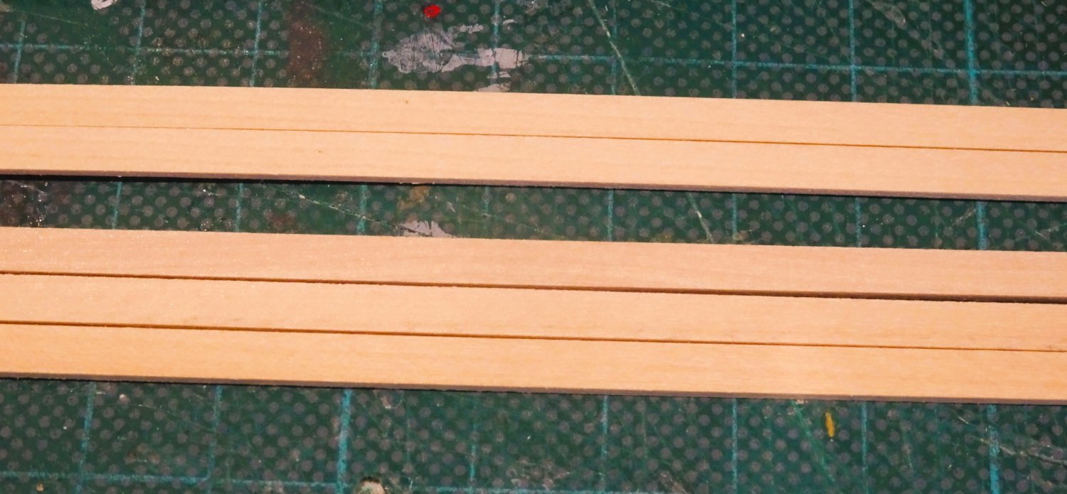
Fresh supplies from the timberyard.
My supply of Boxwood has arrived from Hobbymill, Estonia.
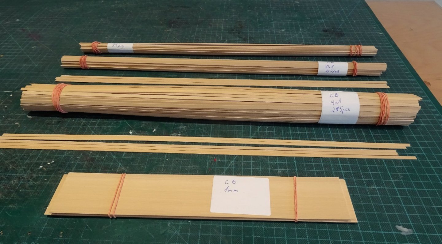
0627

0628
The strips relate to decking and hull planking down to the wale.

0629
0630
The quality looks very good with the strip wood accurately cut to size – thank you Vahur.
I do note that Chris is now offering an ‘Indy’ Boxwood deck planking version for an extra £150 over the basic, which makes it a competitive option, altho’ some wider sheet stuff would be necessary to cut margin planks, unless that is also included.
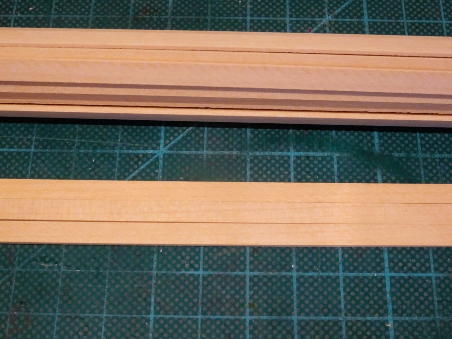
0634
I did ask Vahur to send me a few samples of his coloured Hornbeam. I was curious to see if it could be used to represent the ochre stripe in the area of the gunports.
0635
The colour doesn’t suit my eye, too yellow, and the wrong shade, so I won’t pursue that option.
0636
The lower strip of black Hornbeam has more potential for use as wale timbers, altho' I have not tested it for cut in top and butt planking.
B.E.
31/03/2023
-
Cheers, Guys.
Post Fourteen
Before I fitted the central strake of three I used a micro saw to remove the gunport sections of the upper strake.

0613
I used a length of 8mm x 1.5mm limewood strip to fill in the central gap, a little tapering towards the bow and stern and the fit is good.

0614
0617
I glued the plank to the frames and along the edges of the adjacent planks.

0623
The gunports were the fully opened-up before re-fitting and gluing the pear patterns into place.
0626
The blurb indicates areas where glue should not be applied, relating to the extensions to the bulkheads which will later be removed.
I added double sided tape to these areas to temporarily secure the patterns in the upper areas.
0637
Speed gluing and clamping is the name of the game.
0638
In this shot she looks more 64 than 44, what a lovely chunky beast.
0639

0644
0643
Fitting the patterns concludes this section of the build.
B.E.
30/03/23
- DelF, whitejamest, KARAVOKIRIS and 32 others
-
33
-
1
-
 1
1
-
Good progress Glenn, I think it is the right approach to fit those transom stern planks aft - forward. I always form those planks from a longer length to ensure a smooth curve.
B.E.
- chris watton, hollowneck, Glenn-UK and 1 other
-
3
-
1
-
Beautiful, beautiful work Glenn, a stunning model, the only downside is the anti climax I feel when I go back to my stuff.
B.E.
- FrankWouts and Dave_E
-
2
-
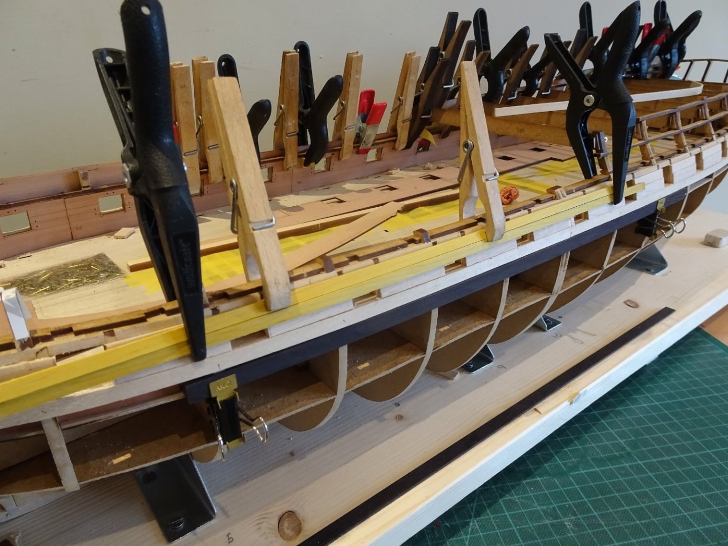
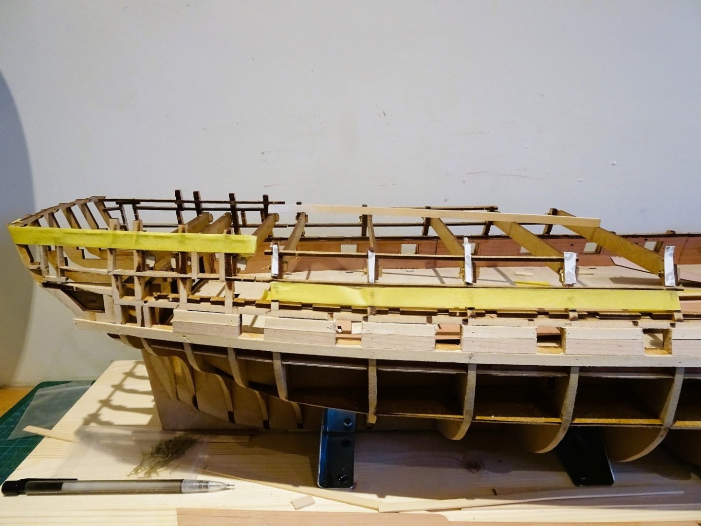
Post Thirteen- completing the fairing
Having applied the test planks at all levels along the hull, paying specific attention to the bow and stern areas I have reached the point where enough is enough.
Or perhaps not quite.
The next stage is to apply the patterns (248/251) around the bow. They are formed around the extension pieces of bulkheads 1 -5, which have a subtle convex shape to them that the pattern should follow.
0596
To this end I did find it necessary to soak the patterns to achieve a good conformity.
0598

0599
I did do a little more fairing in this area to further fay the longitudinal gunport strips into the extension shapes.
0601
0602
These bulkhead extensions are eventually removed, but the subtle shape remains.
0603
The patterns are now re-clamped into position.
0608
A milestone of sorts is now reached with the fixing of the first plank.
The lower plank runs beneath the bow pattern and level with the lower gunport frame.
The lime bends well and with the plank clamped into place, it gets the heat treatment to produce the bow curve.
0607
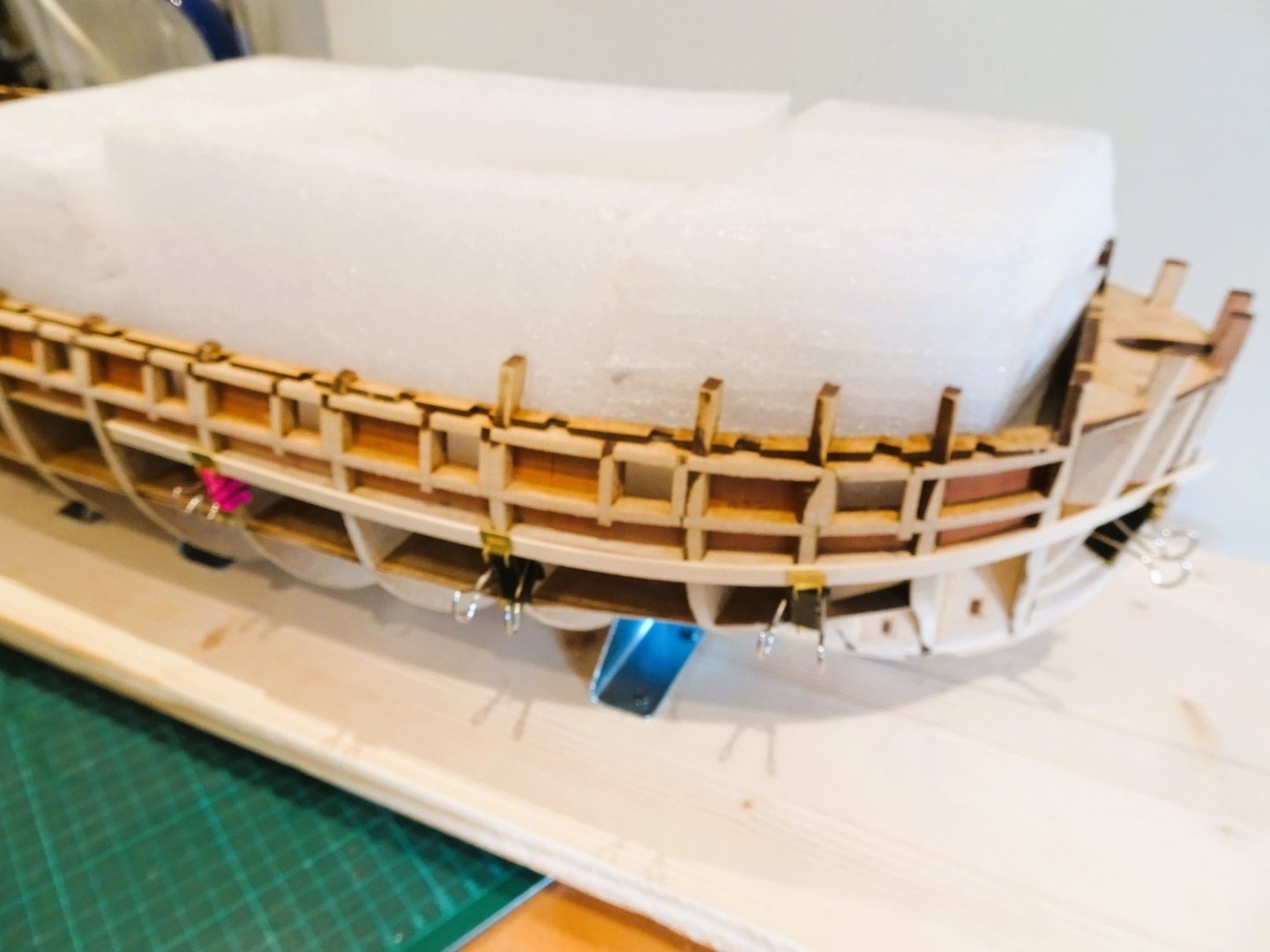
The aft section of this strake has a slight lateral upward curve from bulkhead 12 to the stern, which again was induced using heat after pinning to the hull.
0606
These photos also show the second plank fitted which runs level with the upper gunport frame.
0609
The section between the two planks are now filled, but I found that an additional 6mm strip doesn’t quite fill the space leaving a gap of around 2mm.
I suppose the intention is to fill this with off-cut slivers but I think I have some wider stuff lying around so I’ll dig it out and spile it to fit the space.
B.E.
27/03/23
-
I have to say Gentlemen that I too was far more circumspect when building my single planked Cheerful, with expensive timbers.
I felt comfortable with the mouse for this project, in a way that I have never felt with say the Dremel, which I have never let near any on the model work.
Regards,
B.E.
- BobG, glbarlow, hollowneck and 3 others
-
6
-
Dave, I usually fit the margin plank first, how I form it depends on the severity of the bow curve.
I then plank from the centre outwards and as I reach the margins I cut the joggling into the margin using a fine micro chisel.
The waterway I add once the decking is complete, and then cut the scuppers into it.
At 1:64 scale and smaller I tend to scribe a false scarf joint in the margins.
B.E.
- Rustyj, Chuck Seiler and DaveBaxt
-
2
-
1
-
The 'Mouse ' proved very useful on this very large hull, I found it lightweight, quite controllable, and unlikely to unintentionally over fair unless you really worked at it.
On smaller hulls, I wouldn't bother, a case of courses for horses.
Cheers,
B.E.
-
Post Twelve.
Hull fairing - Day 0ne
Considering this is one of my least favourite aspects of ship modelling, the day went well.
The support board held the hull securely, and the ‘Mouse’ sander performed well.
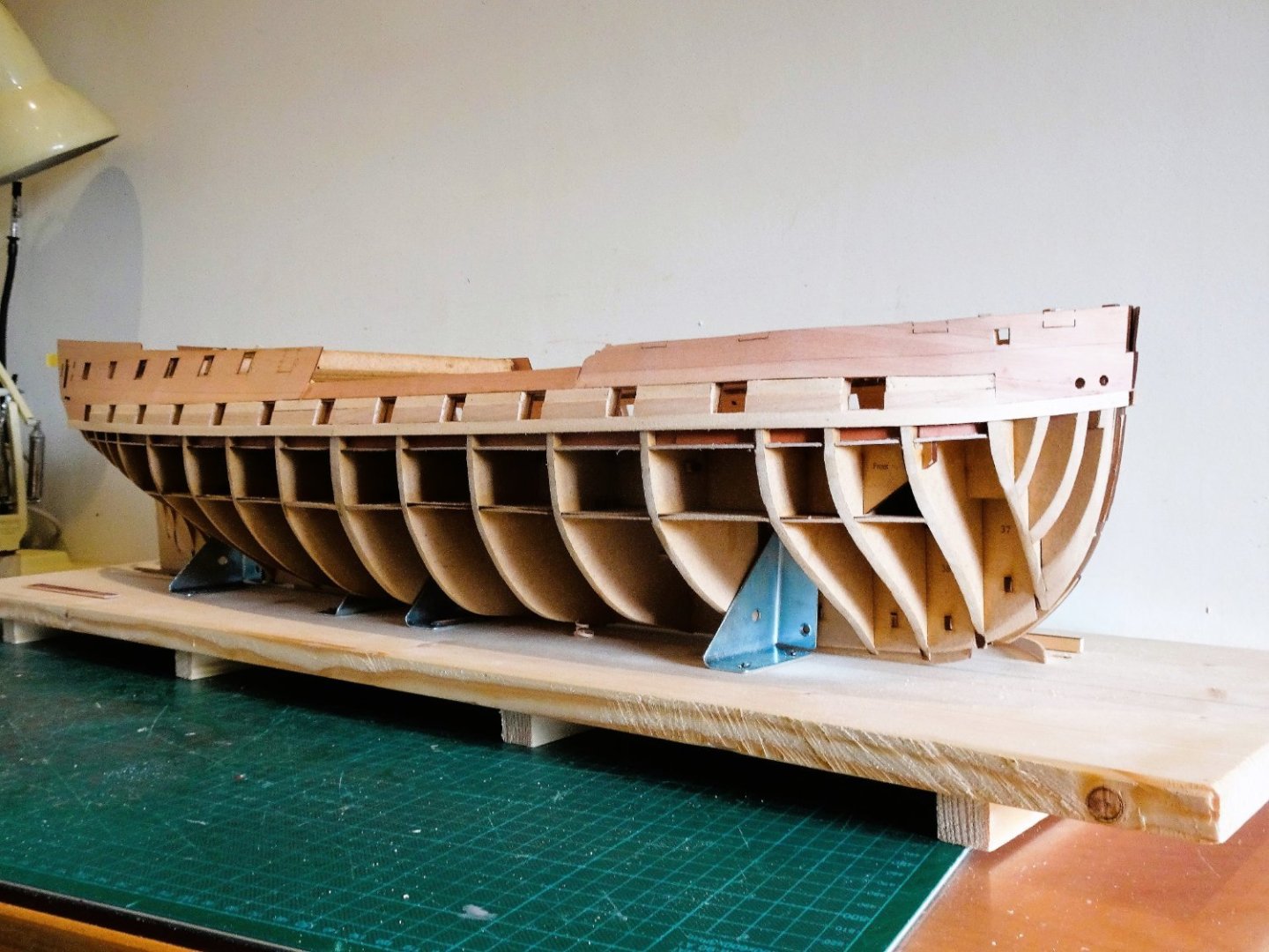
0580
I started with the hull upright and sanded the topsides down to gundeck level.
I started with vertical strokes on the gunport side timbers, and followed on using a long sanding stick along the hull.

0577
0578
The hull was then inverted and the ‘mouse’ brought into play. I used P80 sanding sheets.
I am grateful to Jim and Chris for the heads up on this little tool.

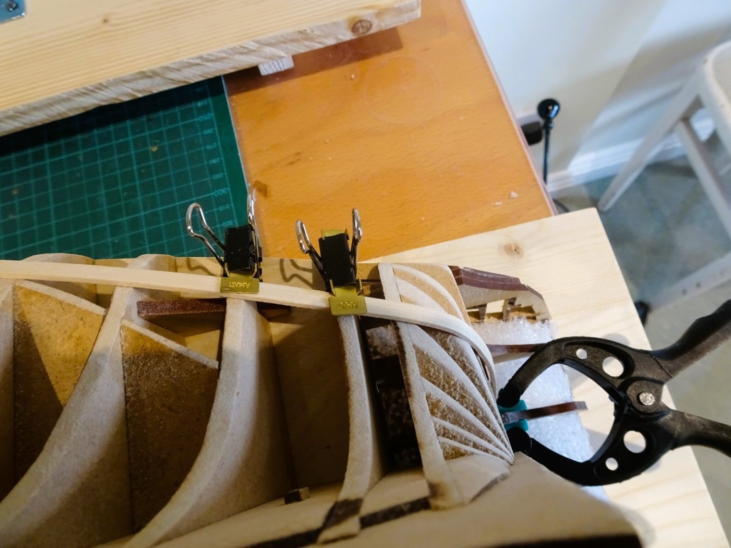
0584

0583
This is the state after around three hours work.
Time now to test the plank lay.
0587
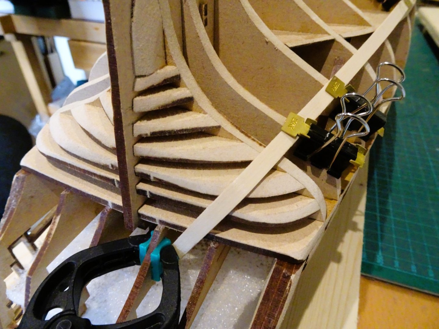
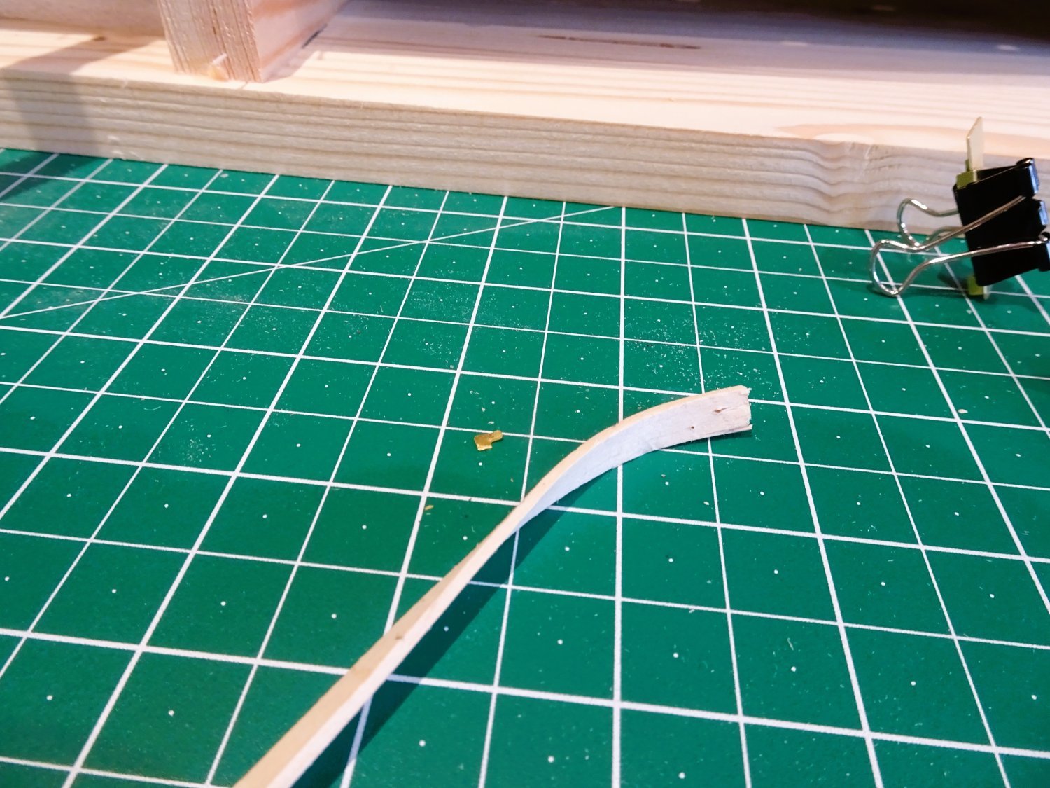
The 1mm thick lime strips bend easily around the bow without any need for pre-bending, but I will pre-bend when I start planking to take the resistance out of the wood.
I am particularly interested in the run of the planks up to the lower transom.
0588
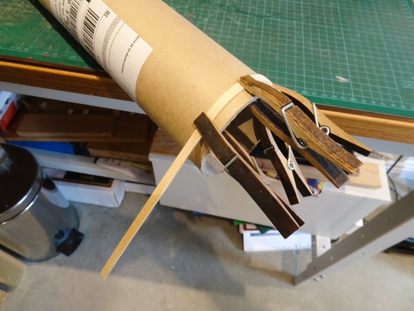
To this end a test plank is pre-bent using hot water and heat.

0590

0591

0592
0593
0594

0595
Looking ok so far, I hate to see any hint of a sharp angle in the plank runs in this area, they should have a smooth and even curve.
That’s enough for one day, I’ll look at it again tomorrow with a fresh eye.
B.E.
24/03/23
- mtaylor, Edwardkenway, Ryland Craze and 30 others
-
31
-
2
-
Thank you Kevin, and Pavel.
@ Kevin - I think 'only slightly ahead' is slightly understating it. 😁
@ Pavel - Thankyou for looking in on my build.👍
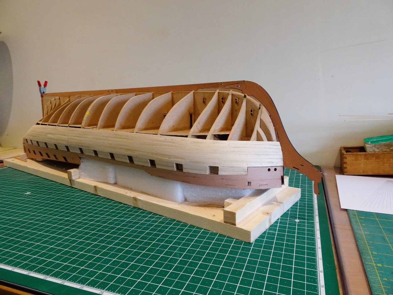
Post Eleven
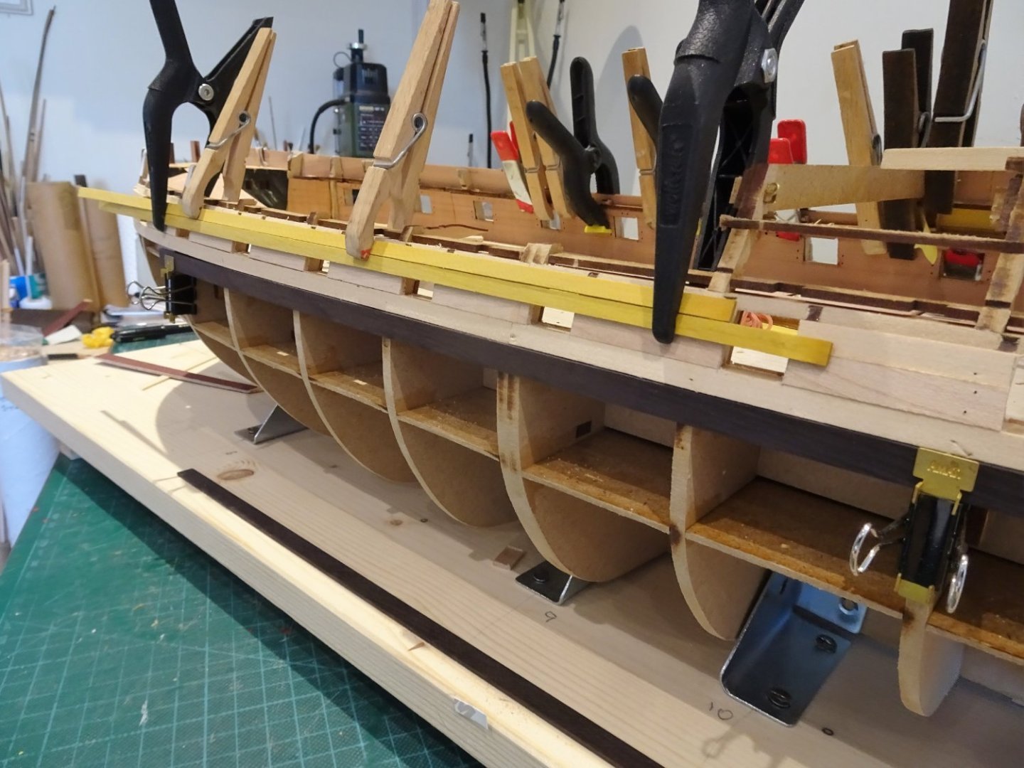
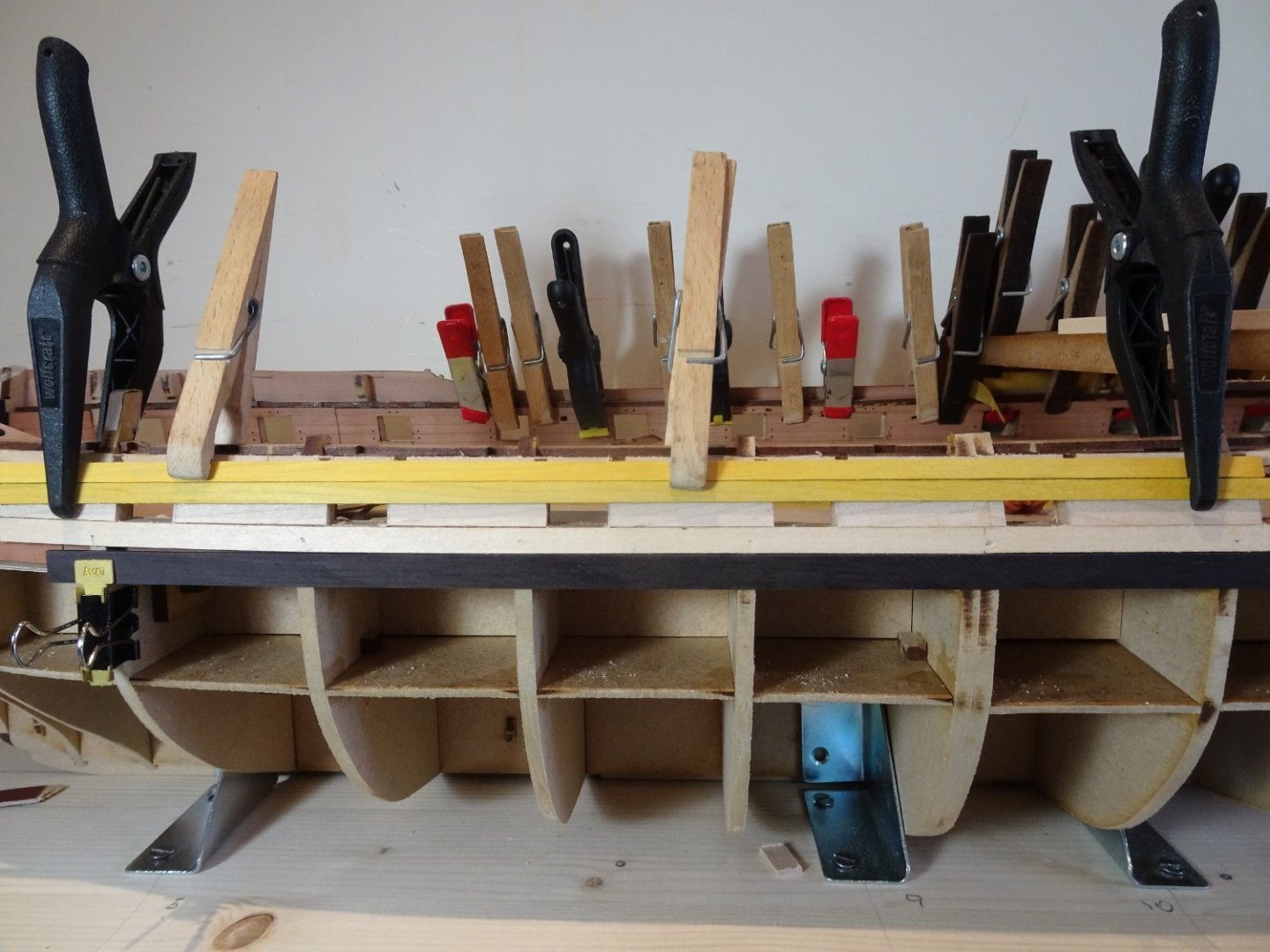
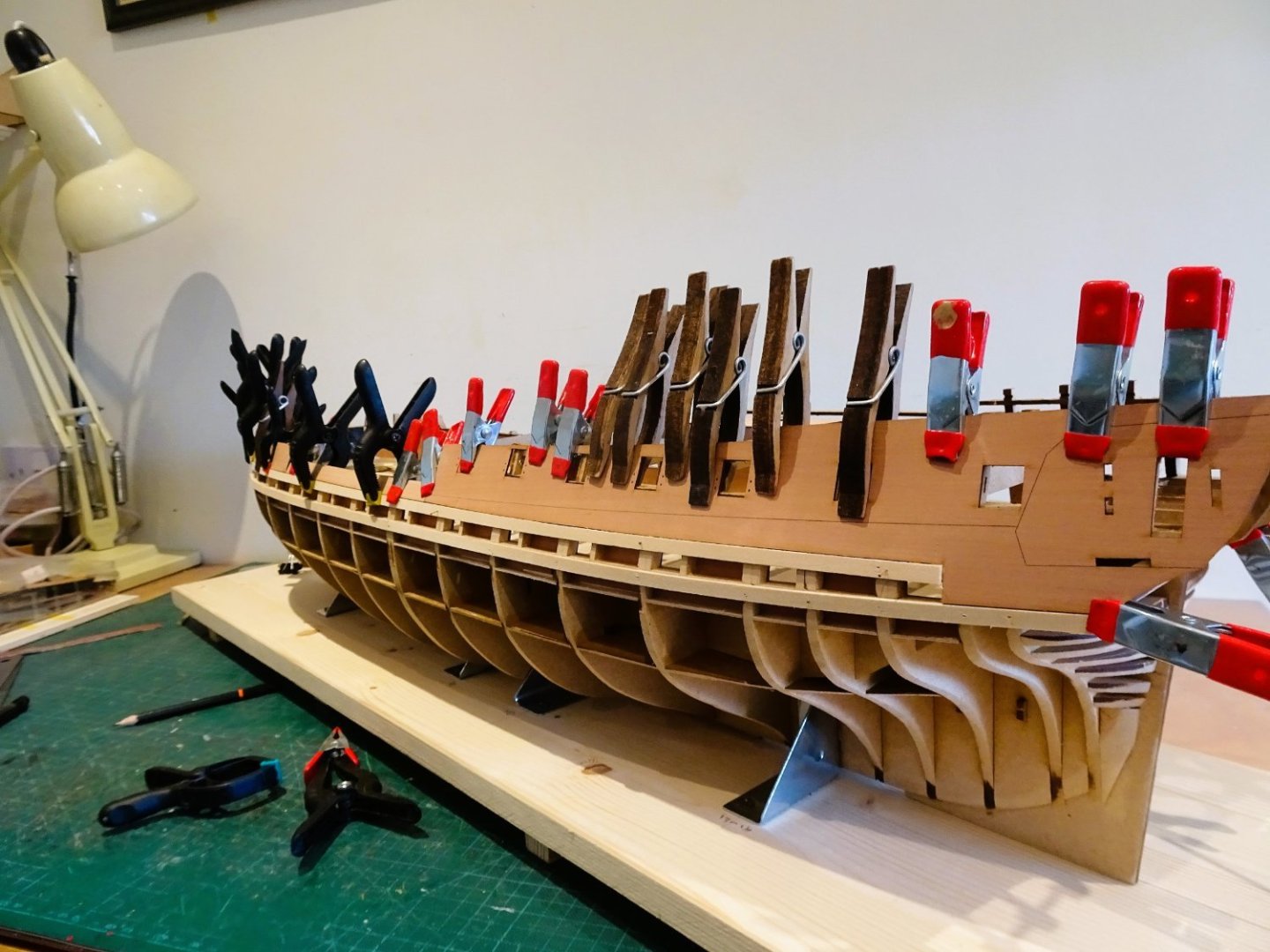
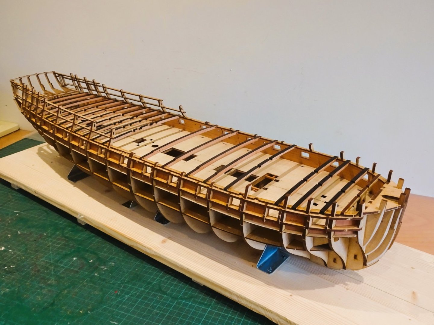
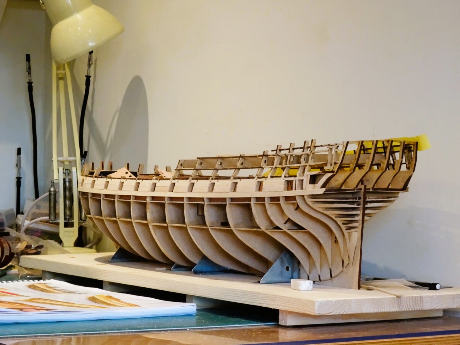
Fairing the Hull.
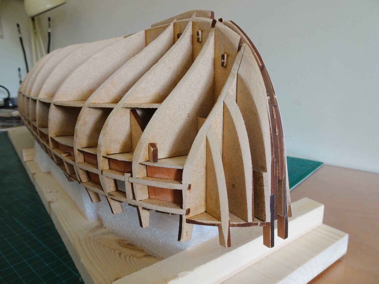
This is such a big beast, I couldn’t quite decide the best way to approach the fairing business.
Not easy to hold while fairing, altho’ holding at angles during the process is almost a certainty.
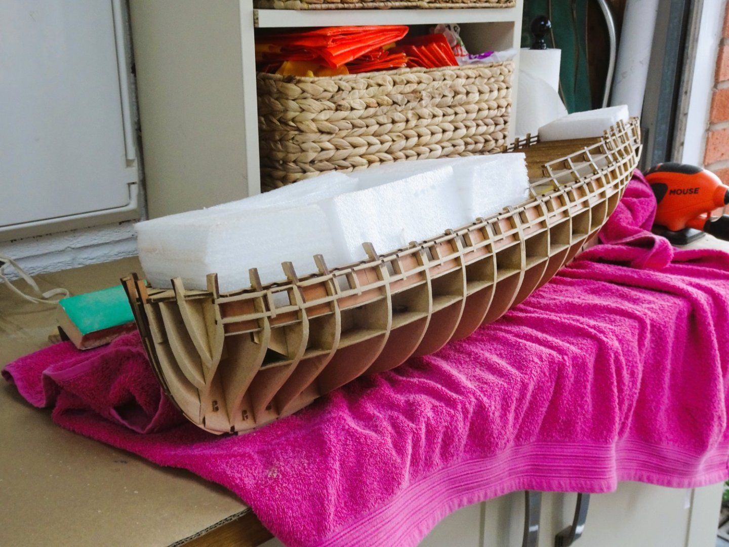
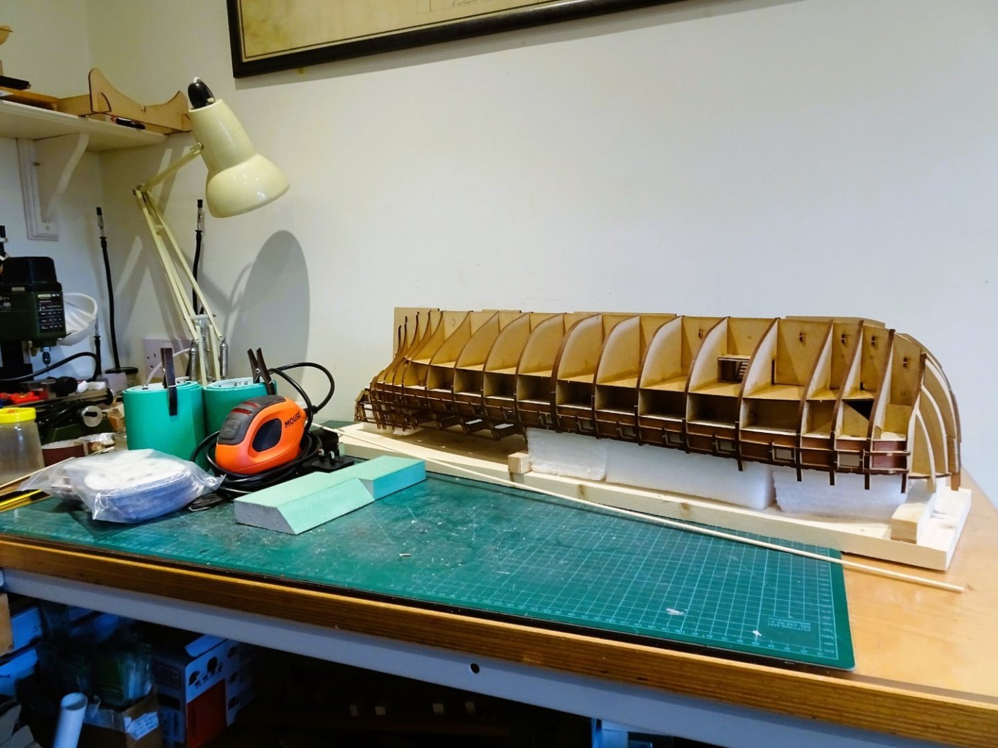
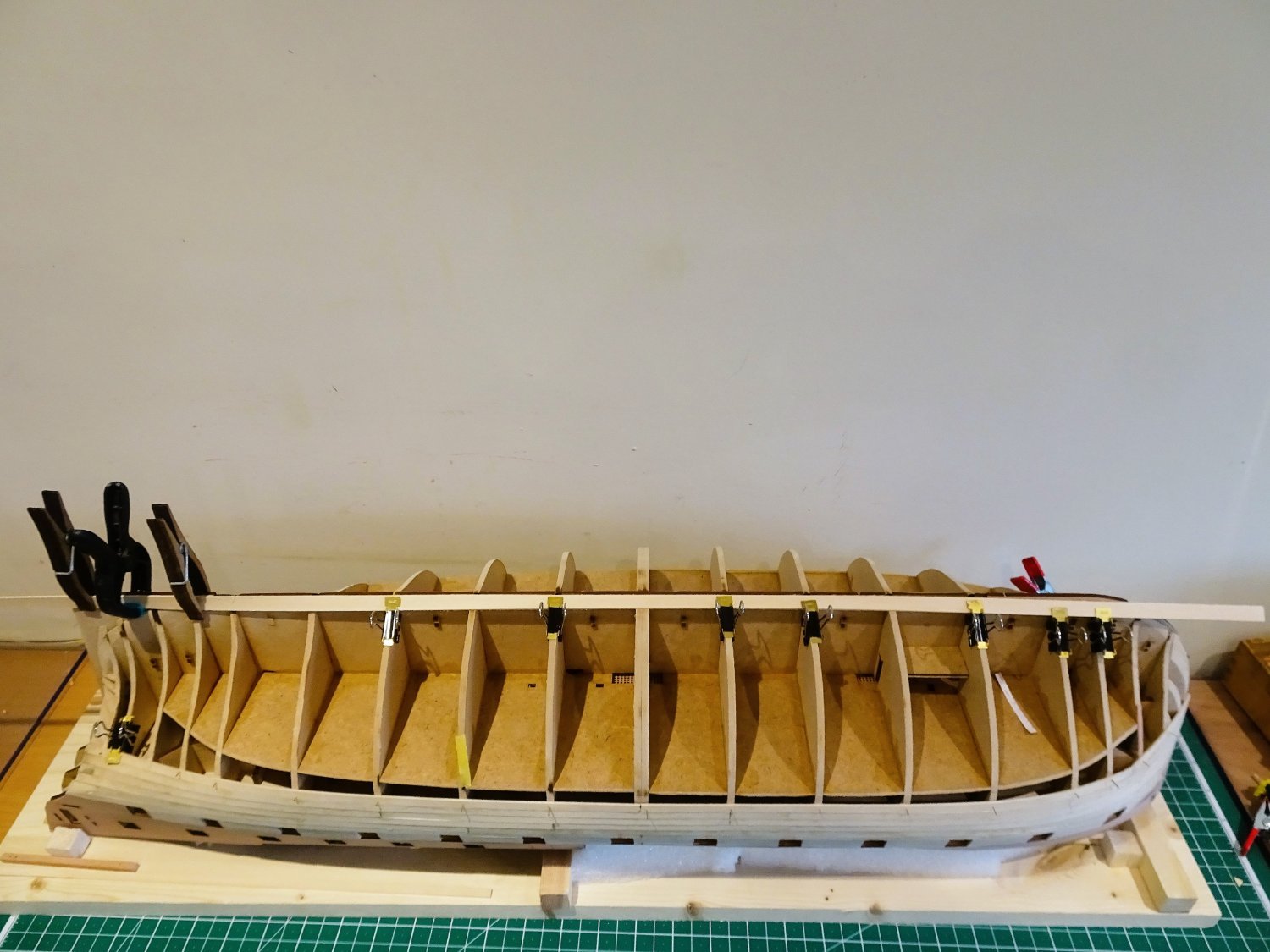
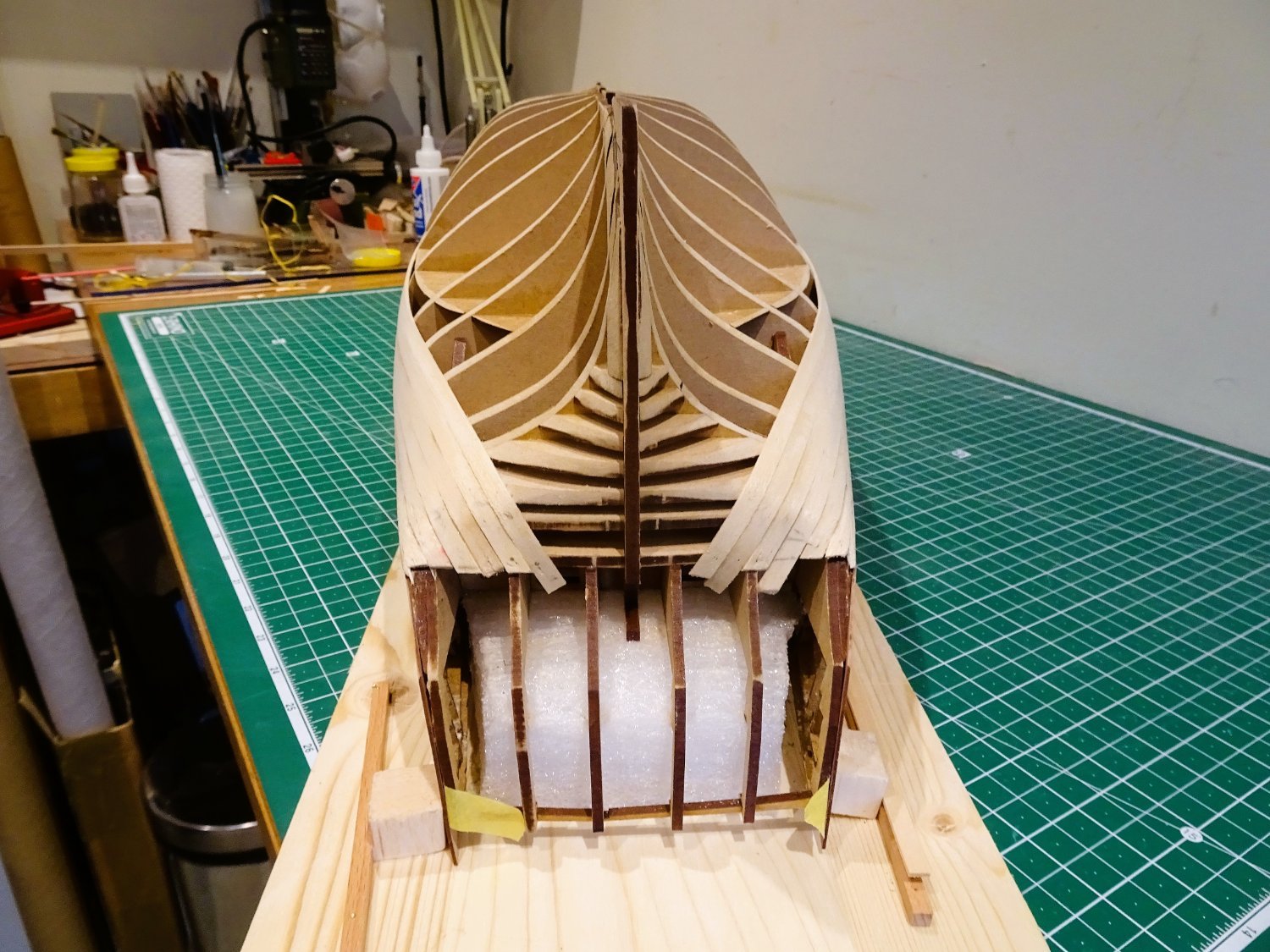
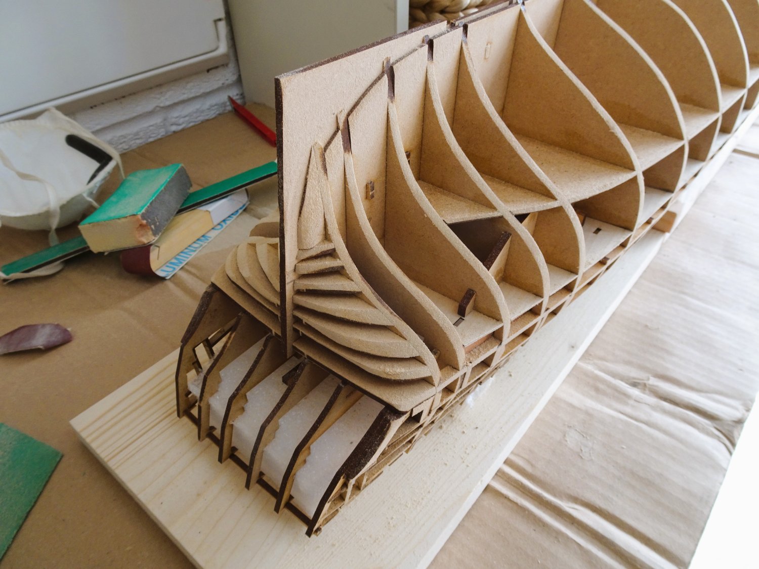
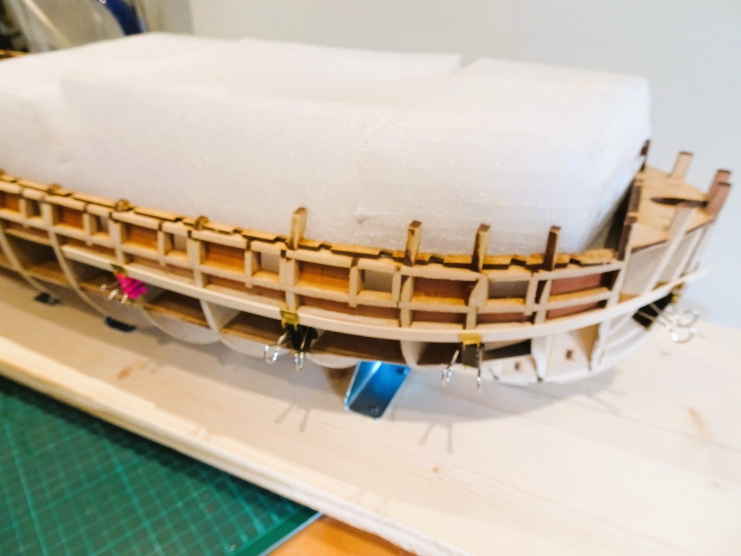
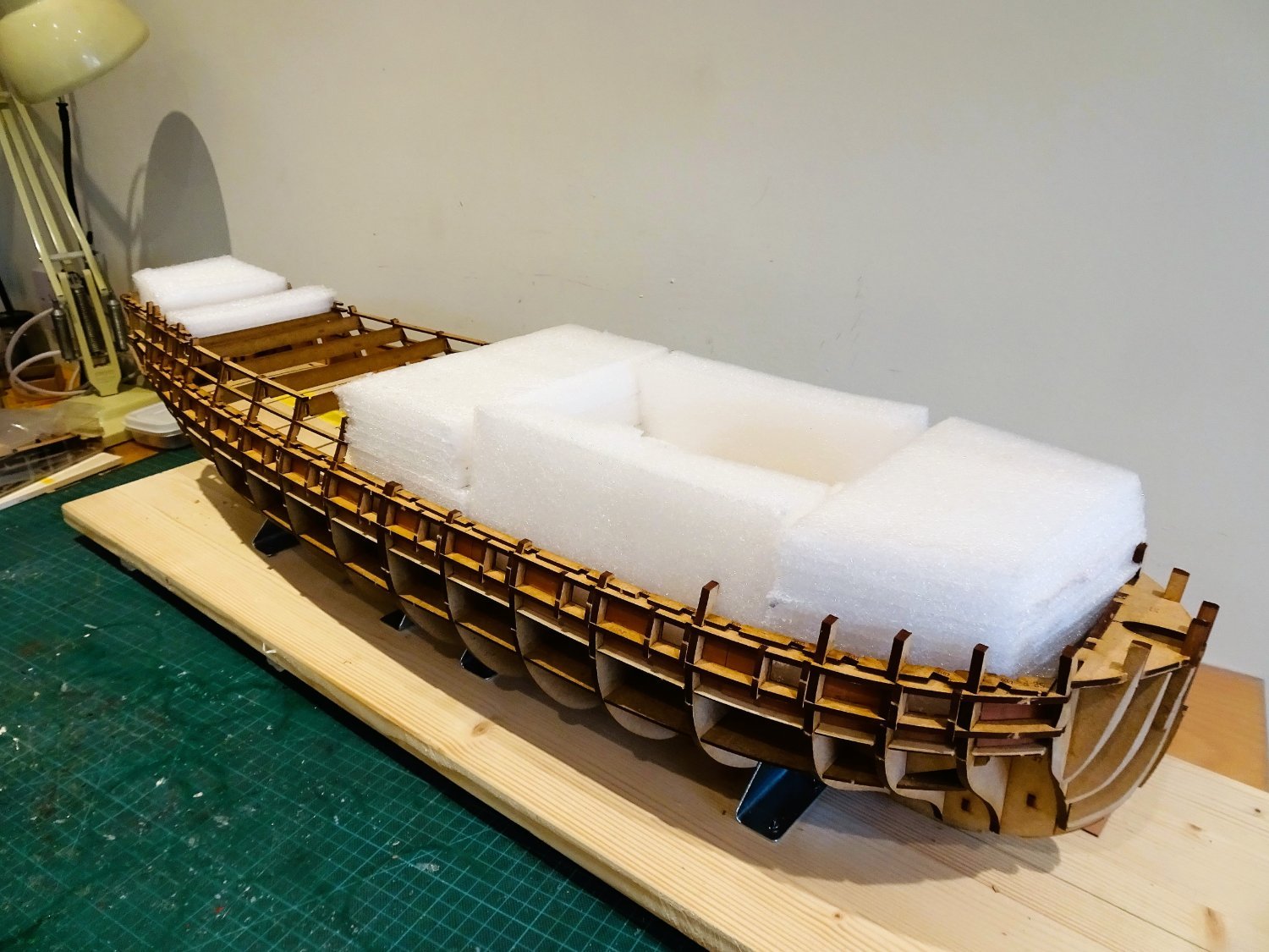
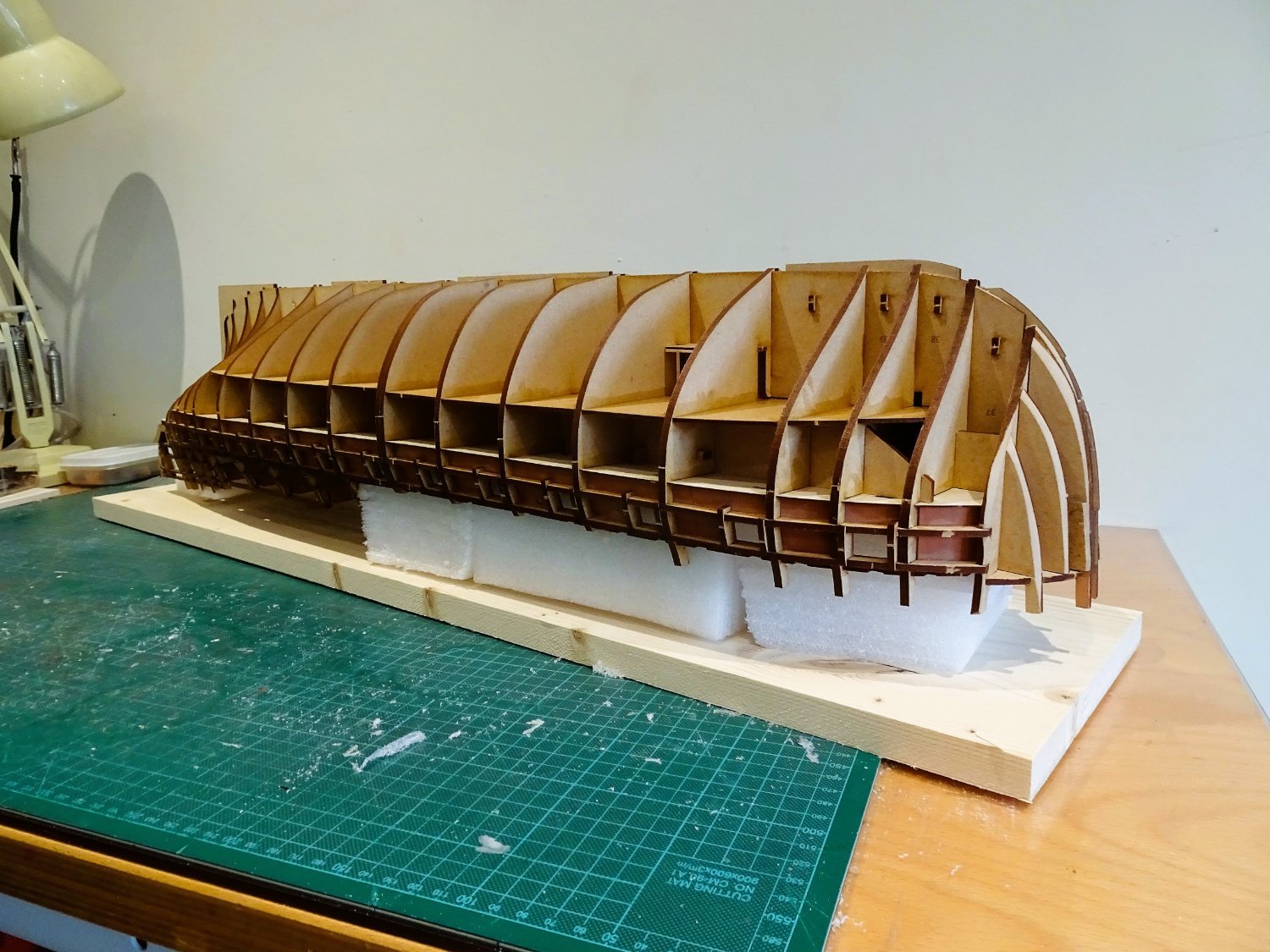
I finally decided that having the hull inverted was the best approach, so I knocked up a simple jig to hold it inverted.

0569
This consists of nothing more than styrene packing material cut to fit snuggly inside the hull and hold it clear of the base during the process.

0570
The packing should protect the delicate bulkhead extensions.

0571
Battens were fitted to the board to hold the hull in place during the sanding.
This arrangement will also double up for the planking and coppering of the hull.
0572
All the necessary stuff is assembled, but I won’t be doing the fairing in my workroom, too much dust.
I need to wait for a quiet, mild day, without the gusting winds we have at present. The forecast for these ‘ere parts doesn’t look that brilliant over the next few days, so I may return to the small boatyard and Medway.
B.E.
23/03/23
- Oldsalt1950, CiscoH, Knocklouder and 22 others
-
25
-
It's amazing the difference a good sanding does for a hull, the lines are looking good Kevin.👍
B.E.
- Kevin, Obormotov, hollowneck and 3 others
-
6
-
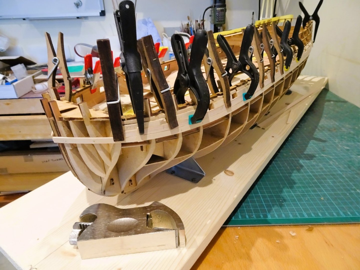
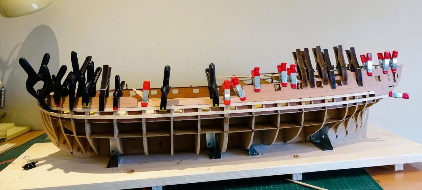
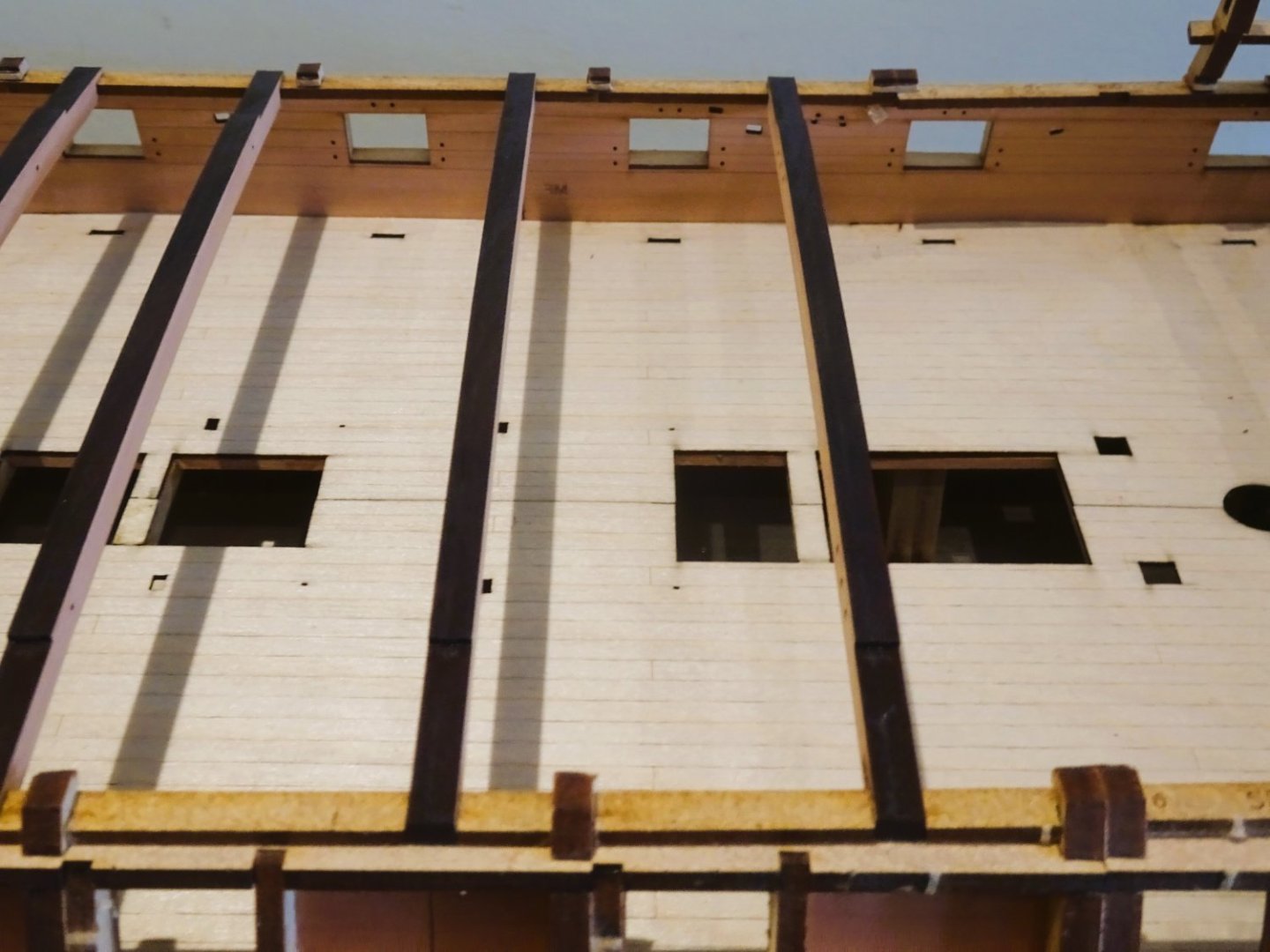
Post Ten.
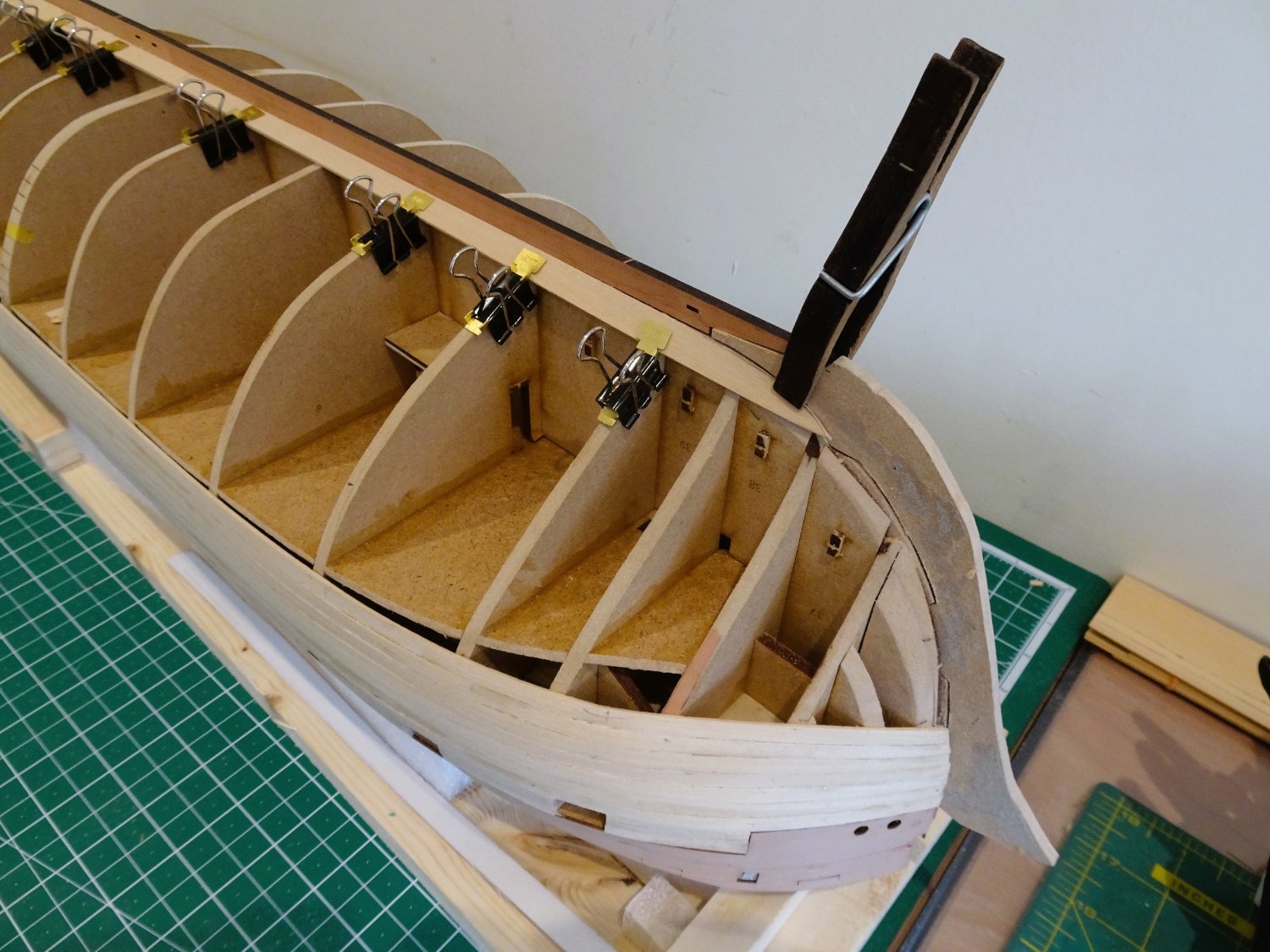
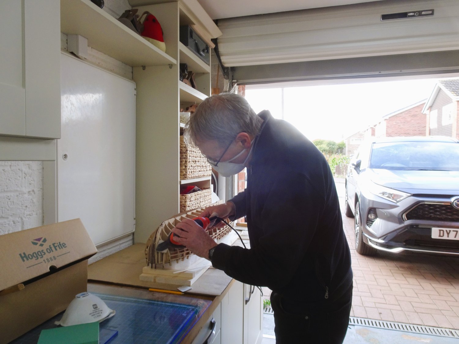
Internal bulkhead frames – sanding – what joy!
The purpose here is to get a smooth line to which attach the inner bulwarks, quick works in 18thc parlance. The spirketting will be added later.
0520
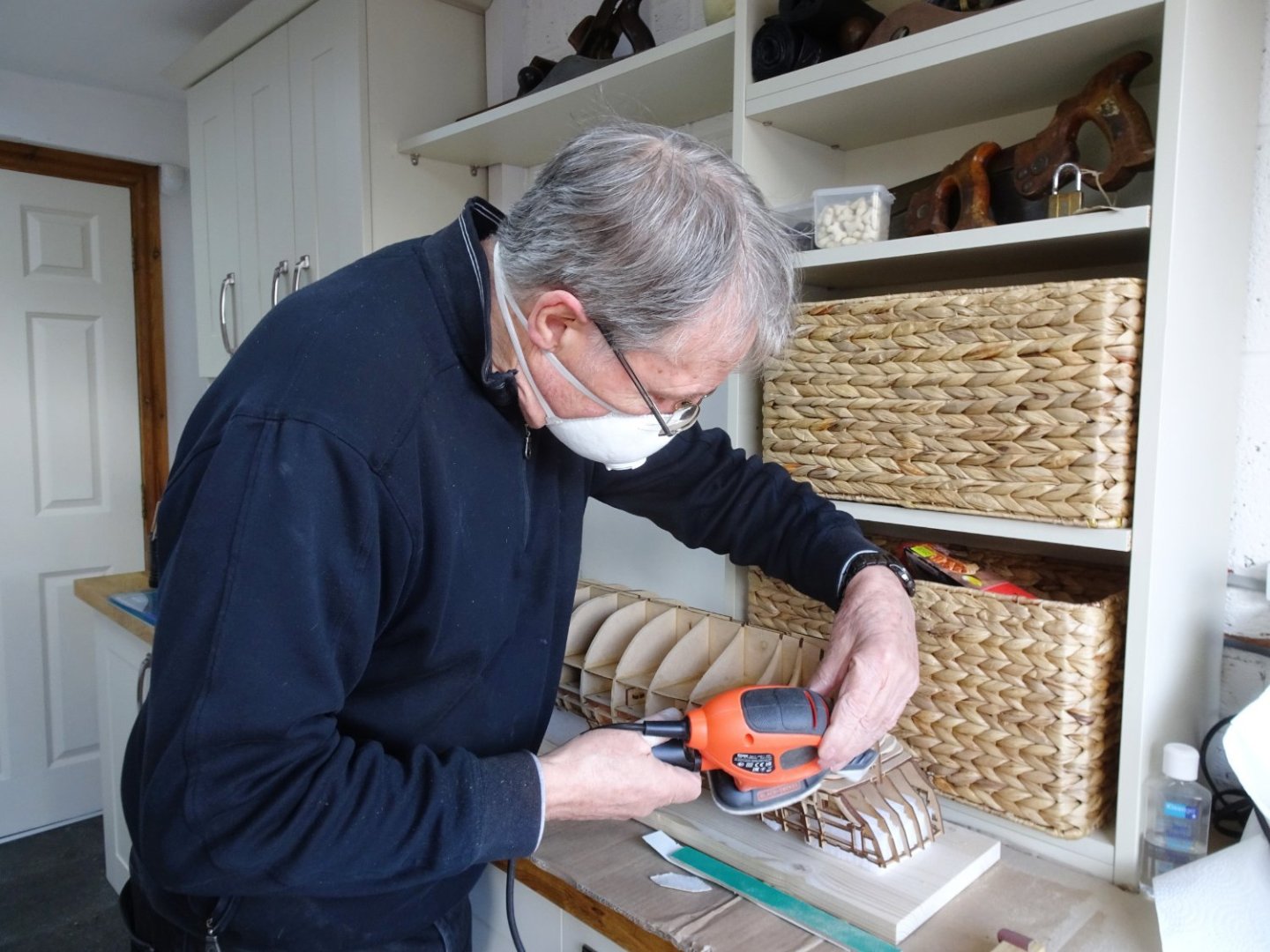
I found it easier to sand the frames with the hull upright, using a combination of an angled finger sander and sheet paper cut to size. Working from the opposite side, my free hand supporting the bulkhead extensions.
Contrary to this posed photo, it is advisable to work with bare lower arms to avoid snagging cuffs etc on the bulkhead extensions.
0547
I used a combination of 80/120 grade papers.
The fit of these parts is very good, a slight bevel on the leading edge of the foremost (optional) part all that was required.
0541
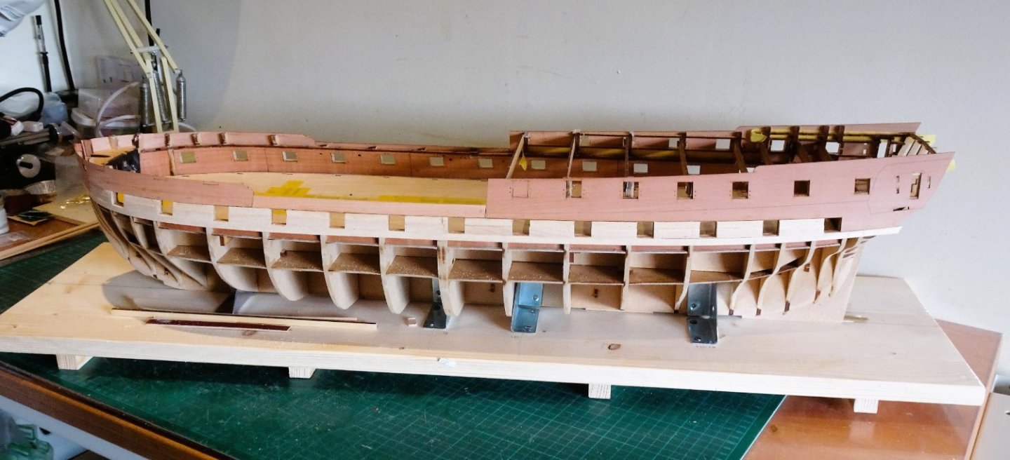
The fit along the deck line is very clean, as are the three join lines between the four sections. The top-line rises a fraction above the upper longitudinal gunport rail which will be sanded flush with the Longitudinal top rail.
Under clamps the sections seemed to conform well to the framing without the need for wetting. I did blast them with heat under clamping.
0544
I applied the starboard side sections sequentially, applying pva directly to the frames to enhance adhesion it was then left overnight to cure.
The procedure was repeated on the Port side next morning.

0551
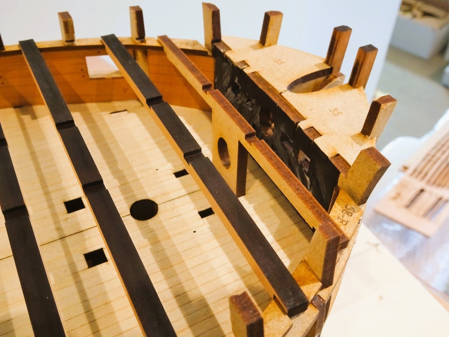
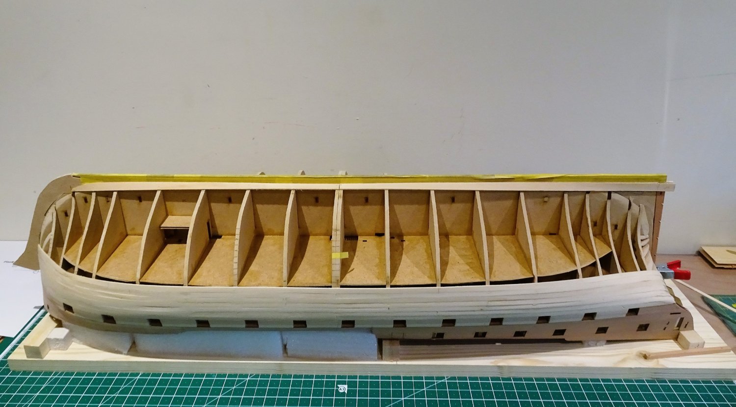
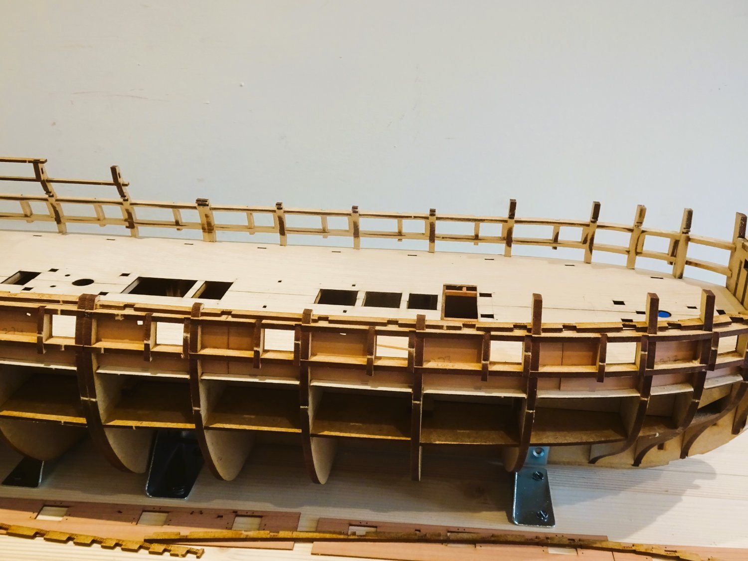
Atop the longitudinal rails are fitted the deck beam strips (Deck clamps) which slotted into the bulkheads without issue. Into these the Upper deck beams are slotted, again without any issues.
0563
0566
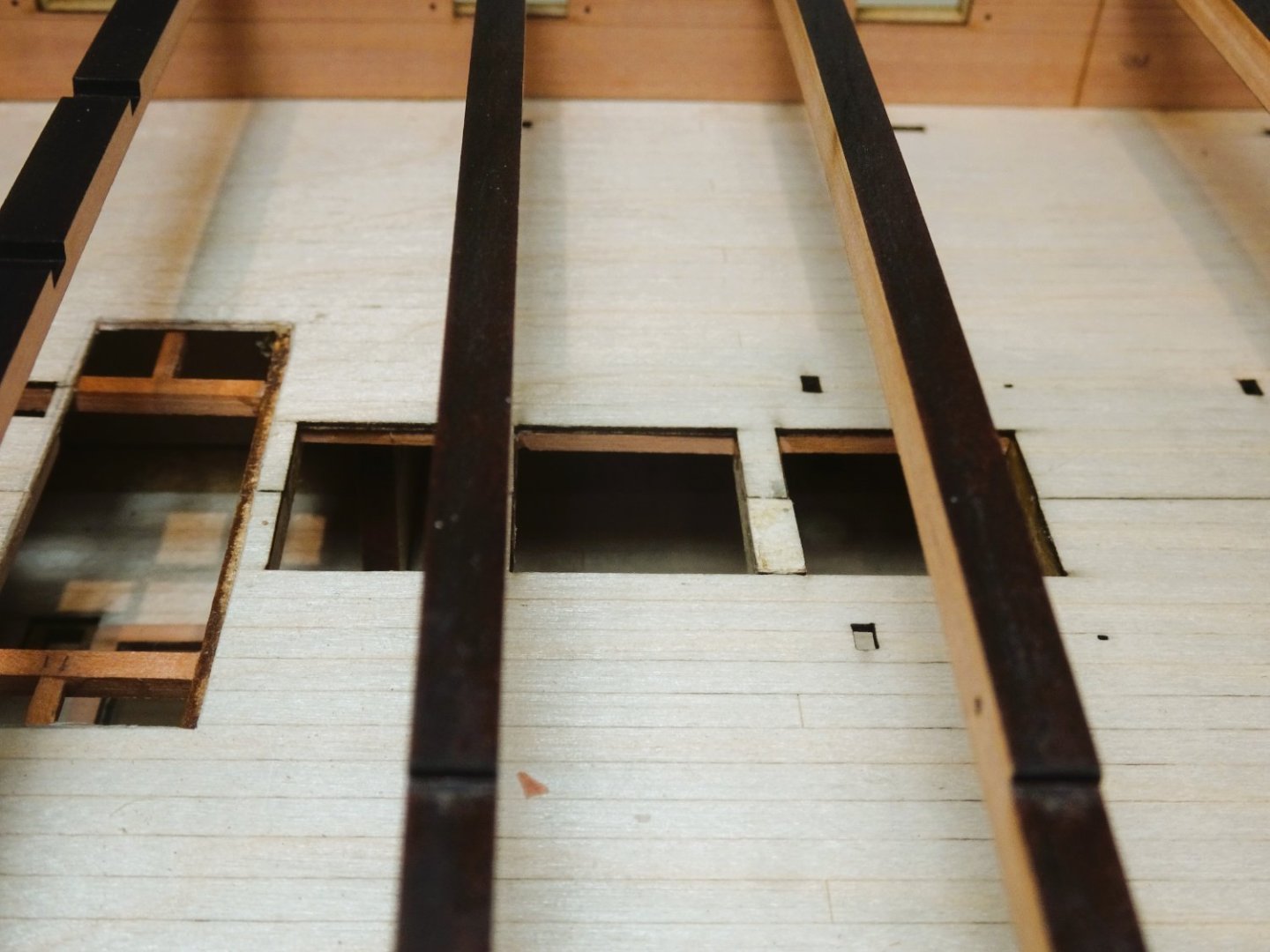
I also took the opportunity to add carlings below the hatchway openings of the deck. I really don’t like to see those thin edges of the false deck, particularly for ladderways and hatches with the gratings removed.
0556
The foremost deck beam incorporates a representation of the Bowsprit stop. This will be removed and re-set some 15mm further back between the legs of the Fore Topsail bitts, which will then allow the manger boards to be installed.
The inboard face of Bulkhead 1 is disguised in shades of black and grey. In an oob build this area is hidden but with my build the Gundeck will be visible thro’ the unplanked upper deck.
It is another smoke and mirrors device to help mask this pob construction compromise.
0554
0555
0562
The Upper deck beams fitted across the deck and slotted seamlessly into place. It is useful having the reference numbers stamped on both beams and clamps.
0567
Once the fit is established the ‘clamping’ strips are glued into place and the beams removed for a later stage.
I now need to stiffen my resolve to begin the hull fairing.
B.E.
22/03/23
-
-


HMS Indefatigable 1794 by Blue Ensign - FINISHED - Vanguard Models - 1:64 scale
in - Kit build logs for subjects built from 1751 - 1800
Posted
Thank you Paul for looking in, and your kind words.
Lovely part of the world you are based in; when I'm not modelmaking I can often be found wandering around Snowdonia. Anglesey, and the Llyn Peninsula.