
.JPG.ca33079f5815b861e67b9c2cccd37982.JPG)

Blue Ensign
-
Posts
4,286 -
Joined
-
Last visited
Content Type
Profiles
Forums
Gallery
Events
Posts posted by Blue Ensign
-
-
Thank you Jim and Chris, so I can leave the deck line alone, and simply sand the top of the bulwark pattern flush with the longitudinal rail.
Cheers,
B.E.
- hollowneck, Oldsalt1950, mtaylor and 1 other
-
 4
4
-
Sorry to appear obtuse Jim, but doesn't the lower edge of the bulwark pattern sit on the deck line?
0541
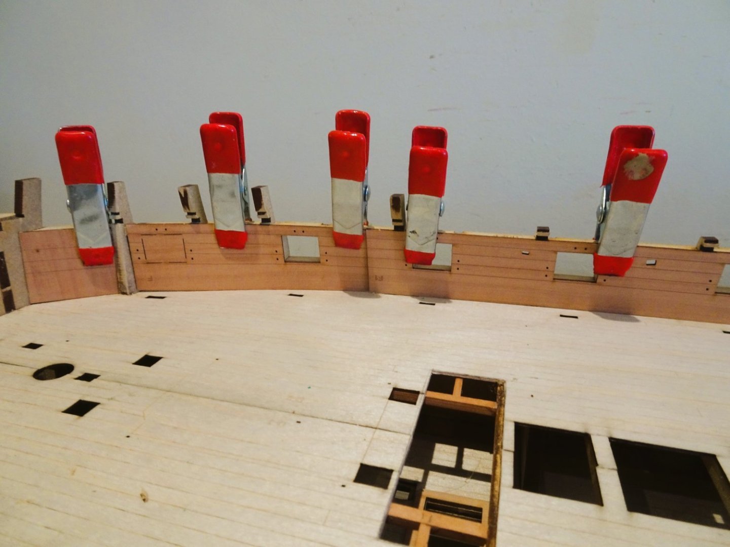
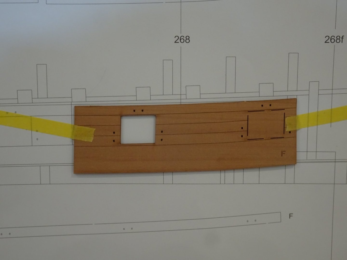
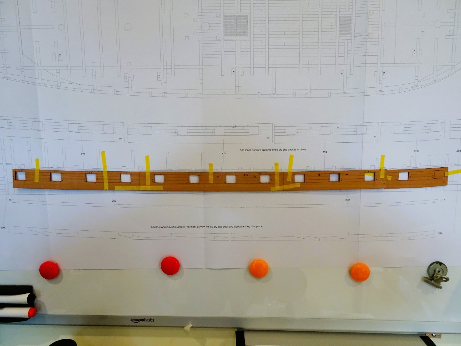
This is how the patterns line -up with the top-line just above the upper rail in places.

0540
0539
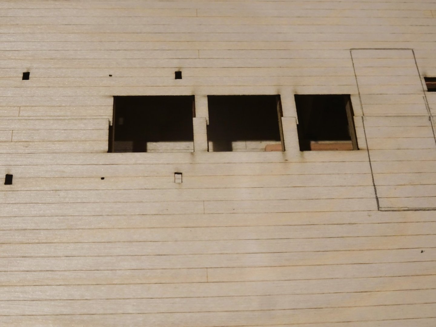
This is how the pattern aligns on the plan against the ports, dipping below the deck-line, and the upper rail, which would suggest a fair amount of trimming off the bottom of the pattern.
This is the cause of my confusion.
B.E.
- thibaultron, mtaylor, fake johnbull and 1 other
-
4
-
A quick question if I may Jim,
Are the inner bulwark patterns meant to run flush with the tops of the gunport upper rails?
I can't quite decide from looking at the profile on plan sheet 2.
My inclination is to fit them as is with the tops flush with the top of the rails which I think you have done.
Thank you,
B.E.
- hollowneck, mtaylor and thibaultron
-
3
-
Thank you Ron,
I do prefer my cheese unadorned, and preferably with a glass or three of a fine merlot. To sit outside on a fine summer evening, after a satisfying day in the workshop, or out walking the hills with my Spaniel, - perfection. 😊
Dammit Ron, you’ve put me in mind for the very thing😉
Cheers, 🧀🍷
B.E
- mtaylor, hollowneck, Hubac's Historian and 3 others
-
5
-
 1
1
-
It is used for electrical insulation purposes, and is widely available - Amazon, e-bay, hardware stores etc;
I used it on my Alert build for the banding you describe, the anchor stock bands, and the bands around the main boom.
I most recently used it to form the iron bands around the masts on my Sphinx build.
Regards,
B.E.
- Peanut6, Thukydides and Obormotov
-
3
-
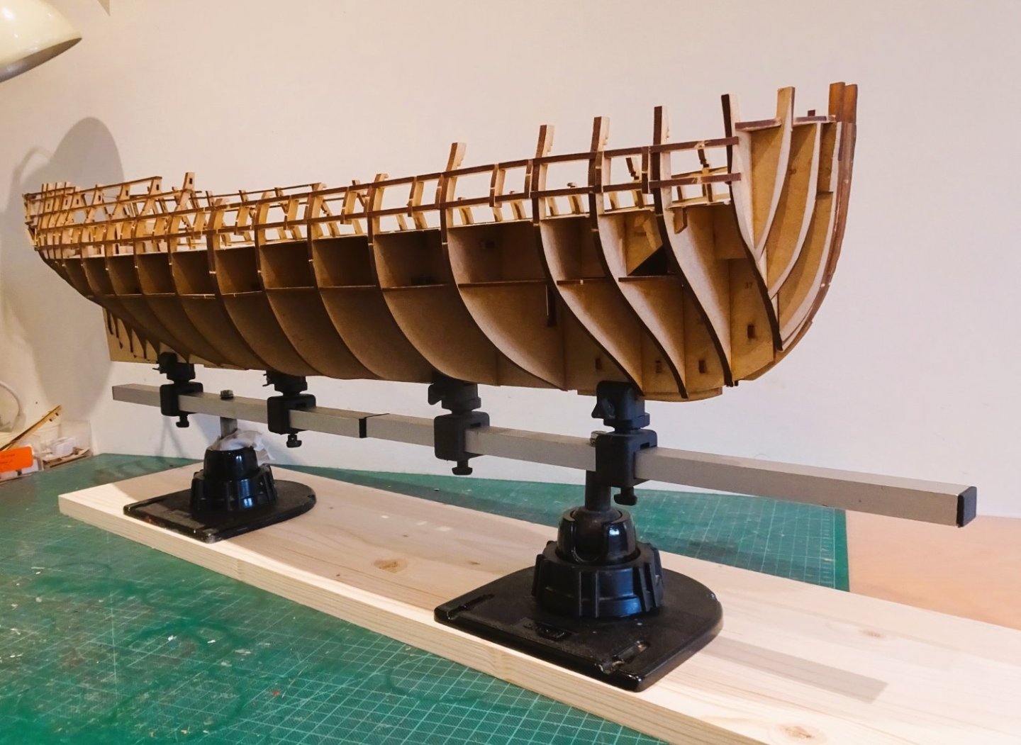
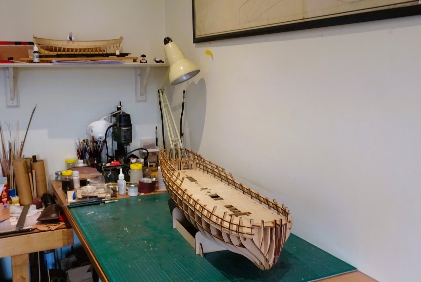
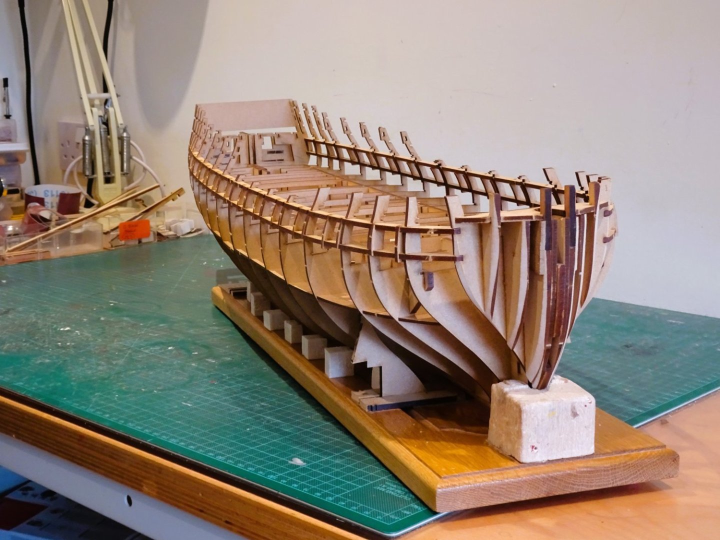
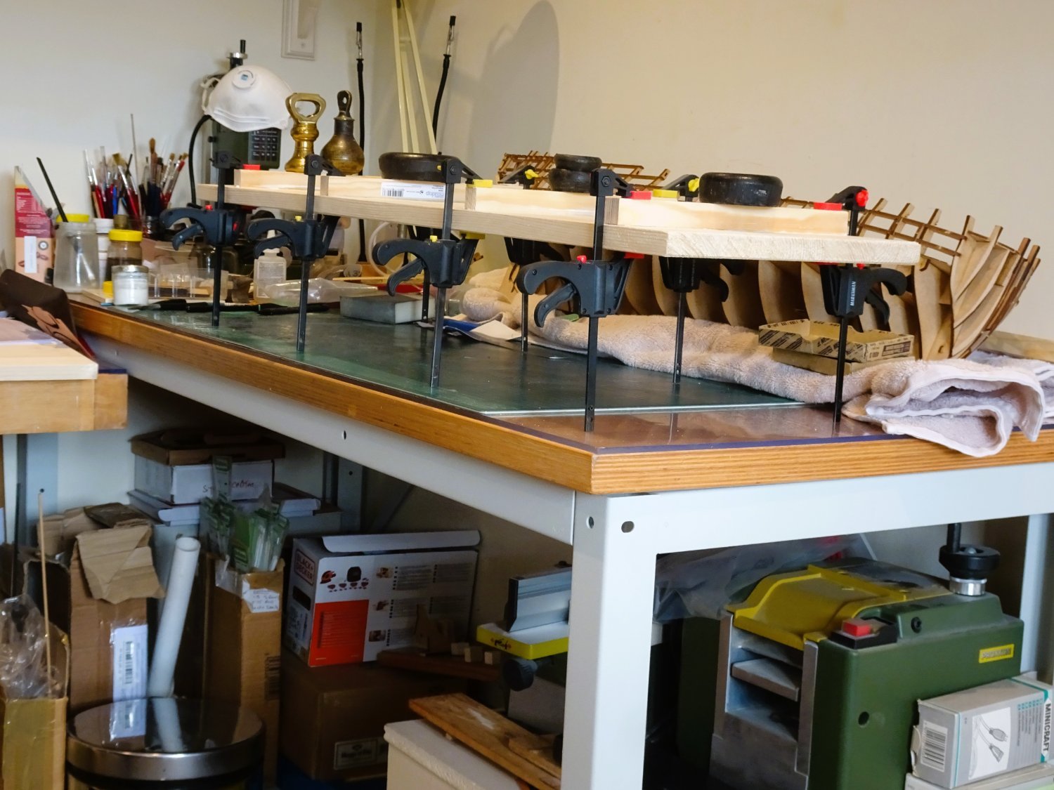
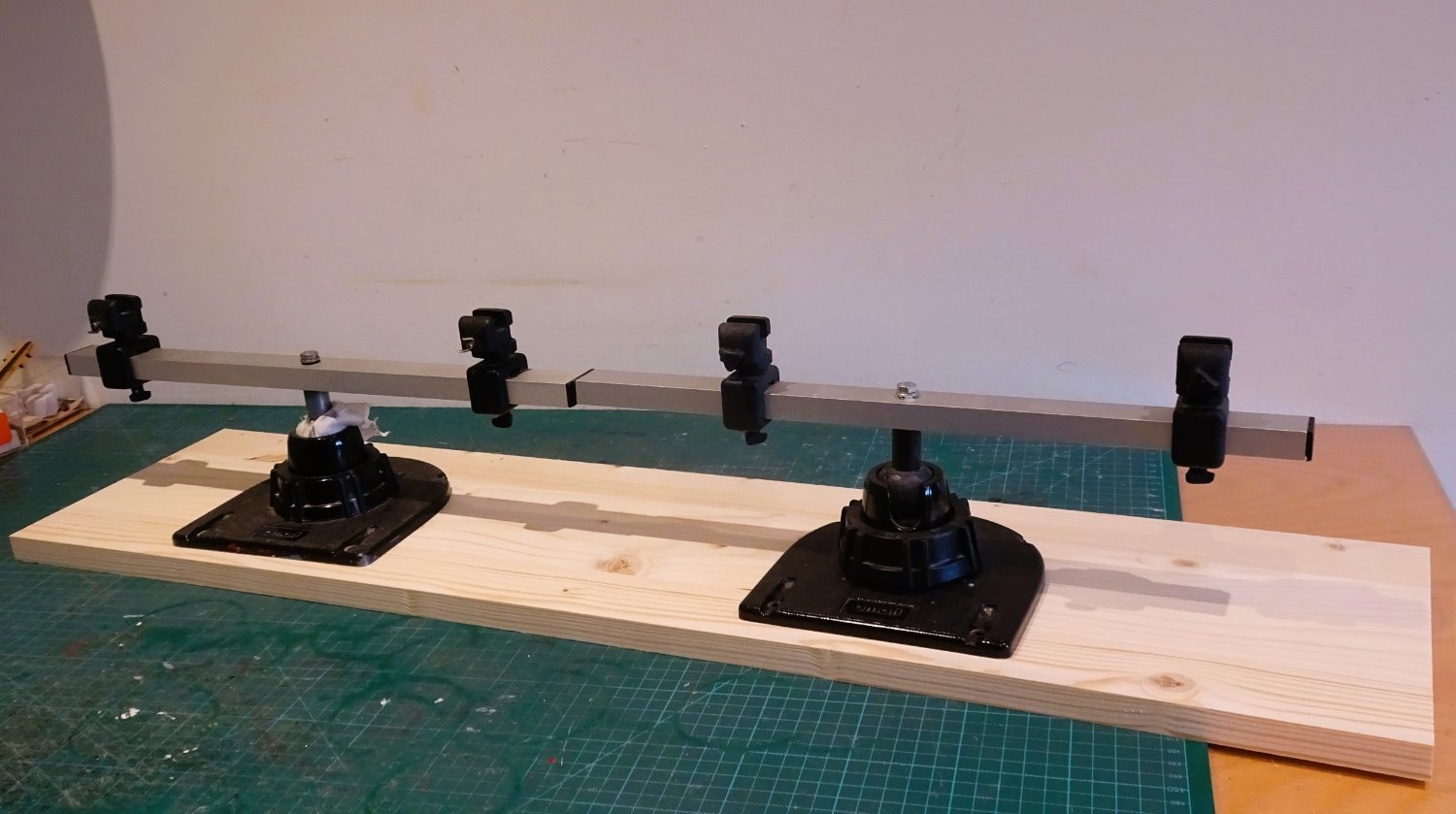
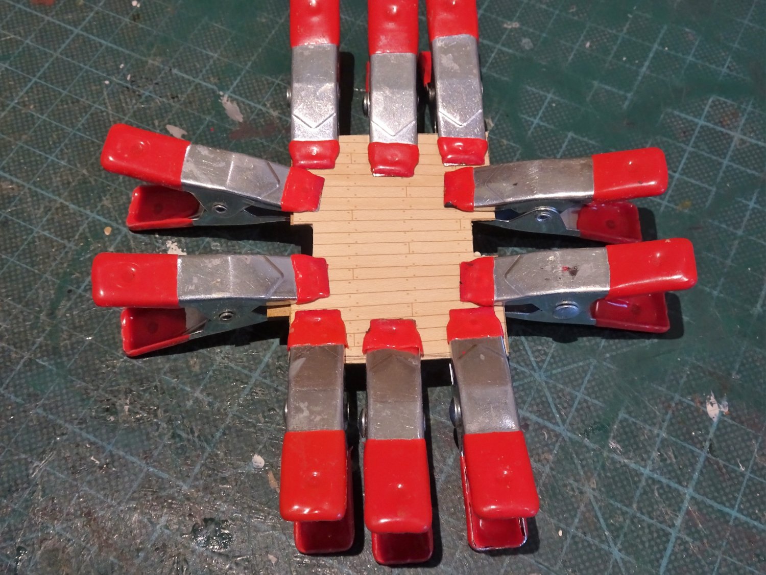
Post Nine.
Basics
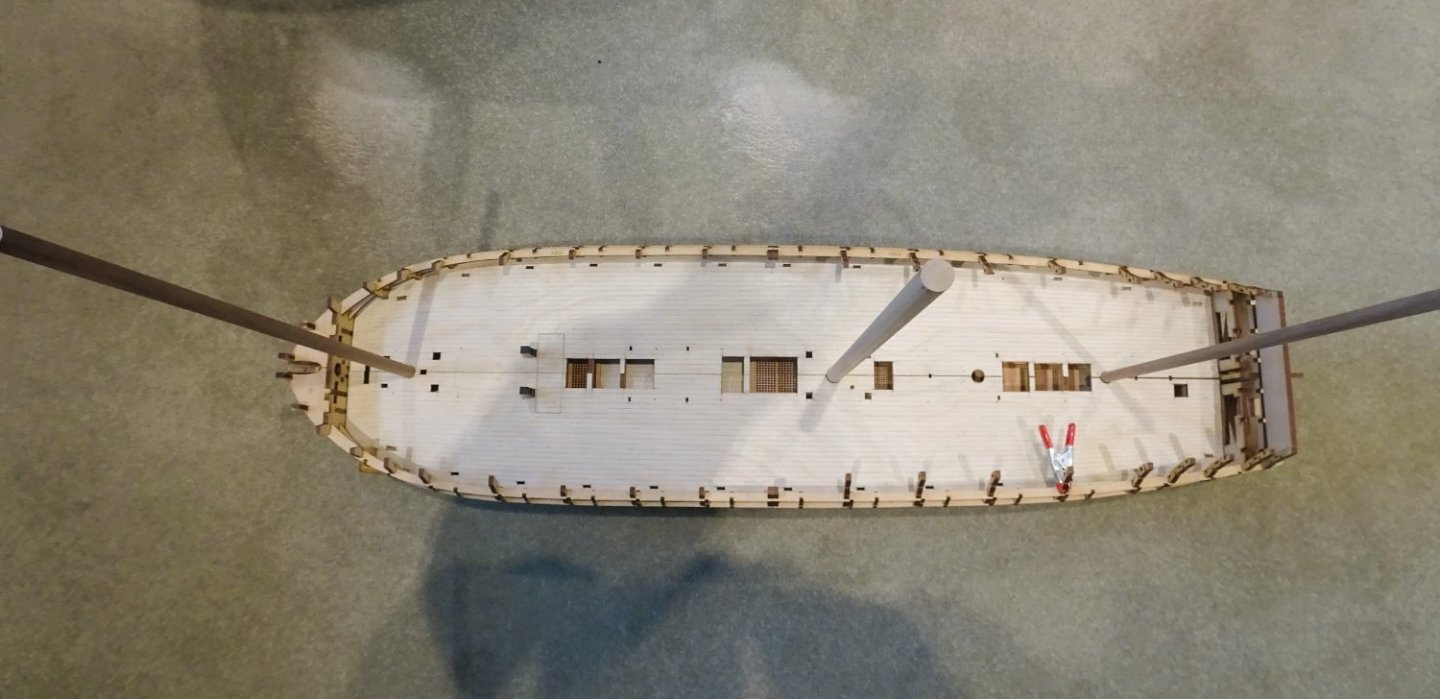
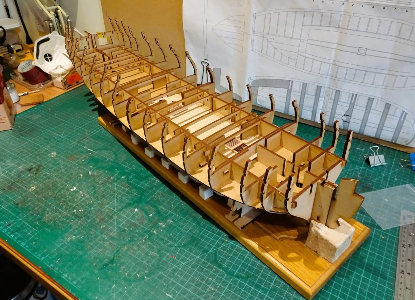
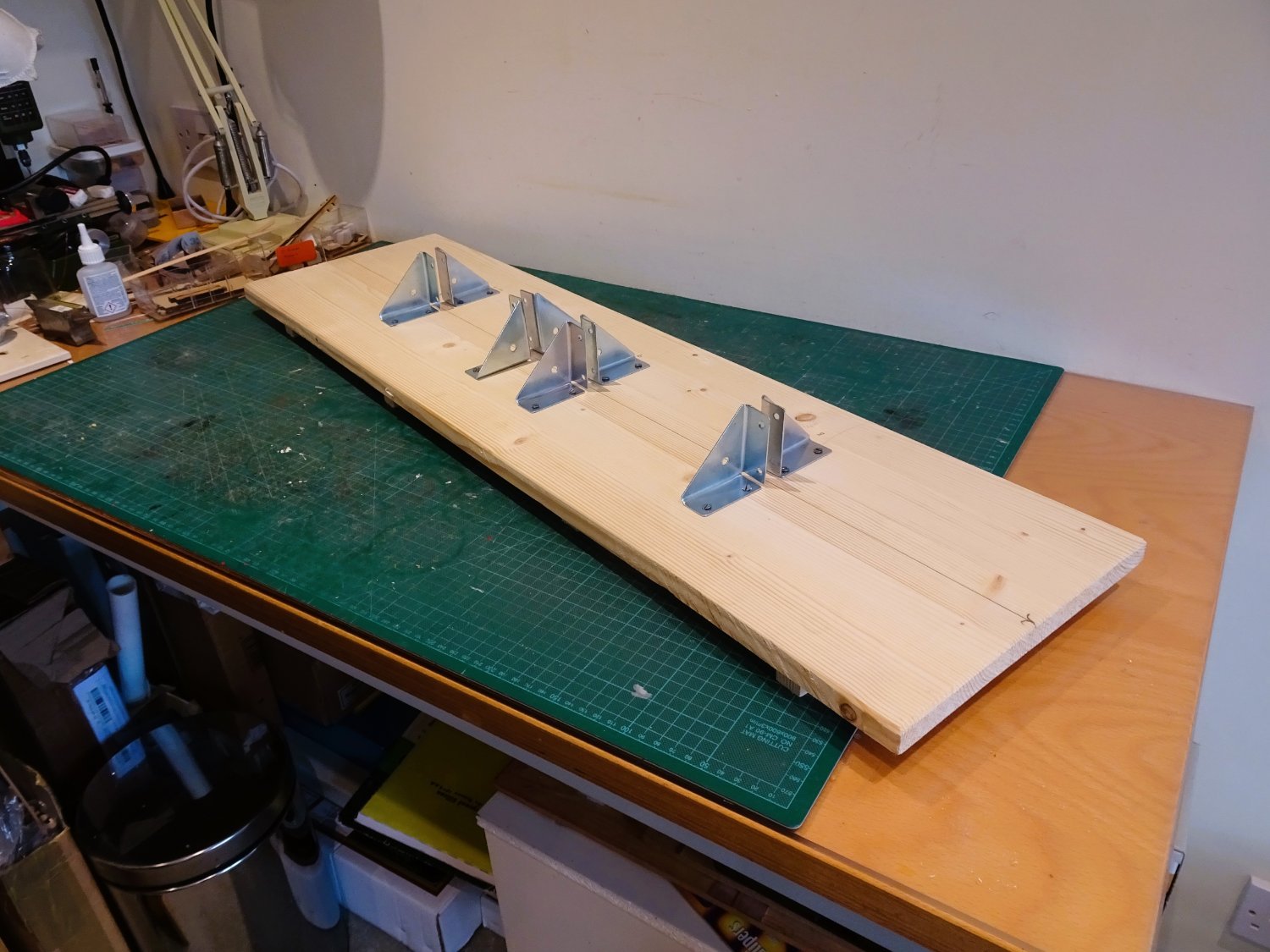
Today I took time out to prepare a building board for Indy.
A plain board of 900 x 245mm indicates the size of this beast.

0526
Battens are placed on the underside to both raise the board a little and provide space for finger grips, this is /will be a heavy hull to move about. The space is also good for clamping purposes.
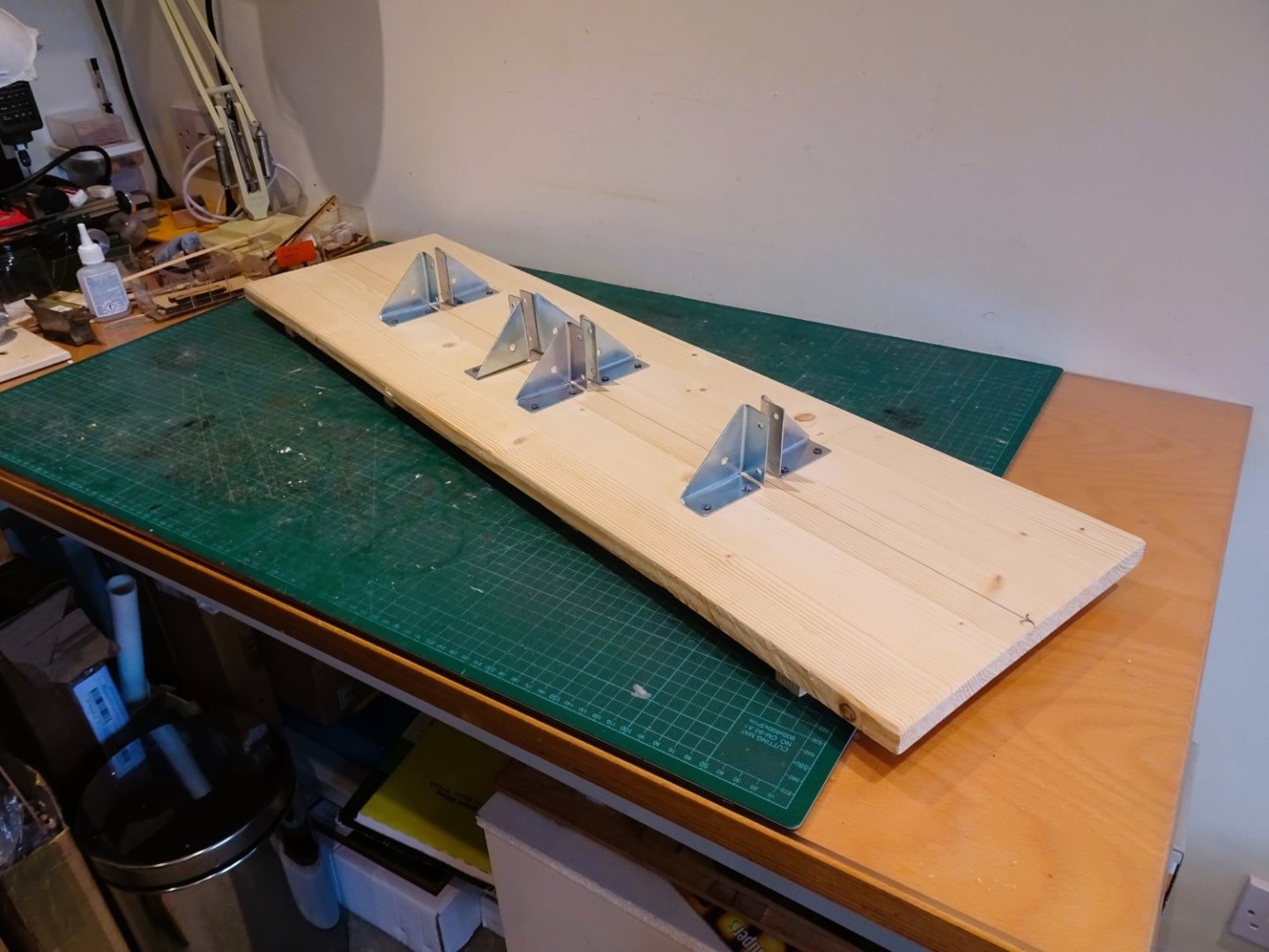
0530
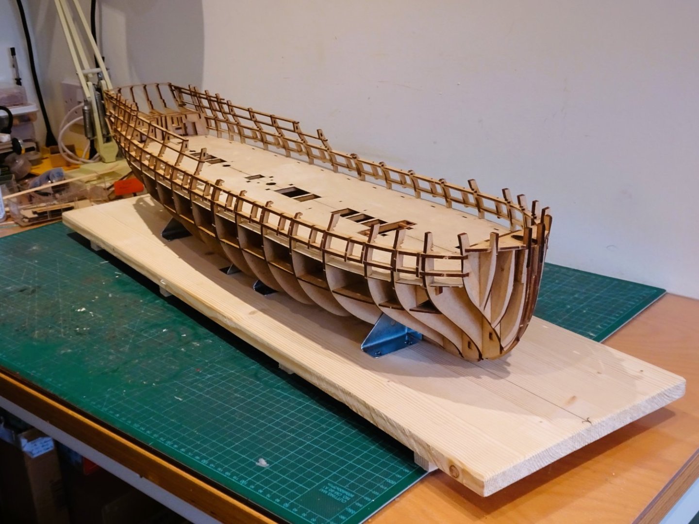
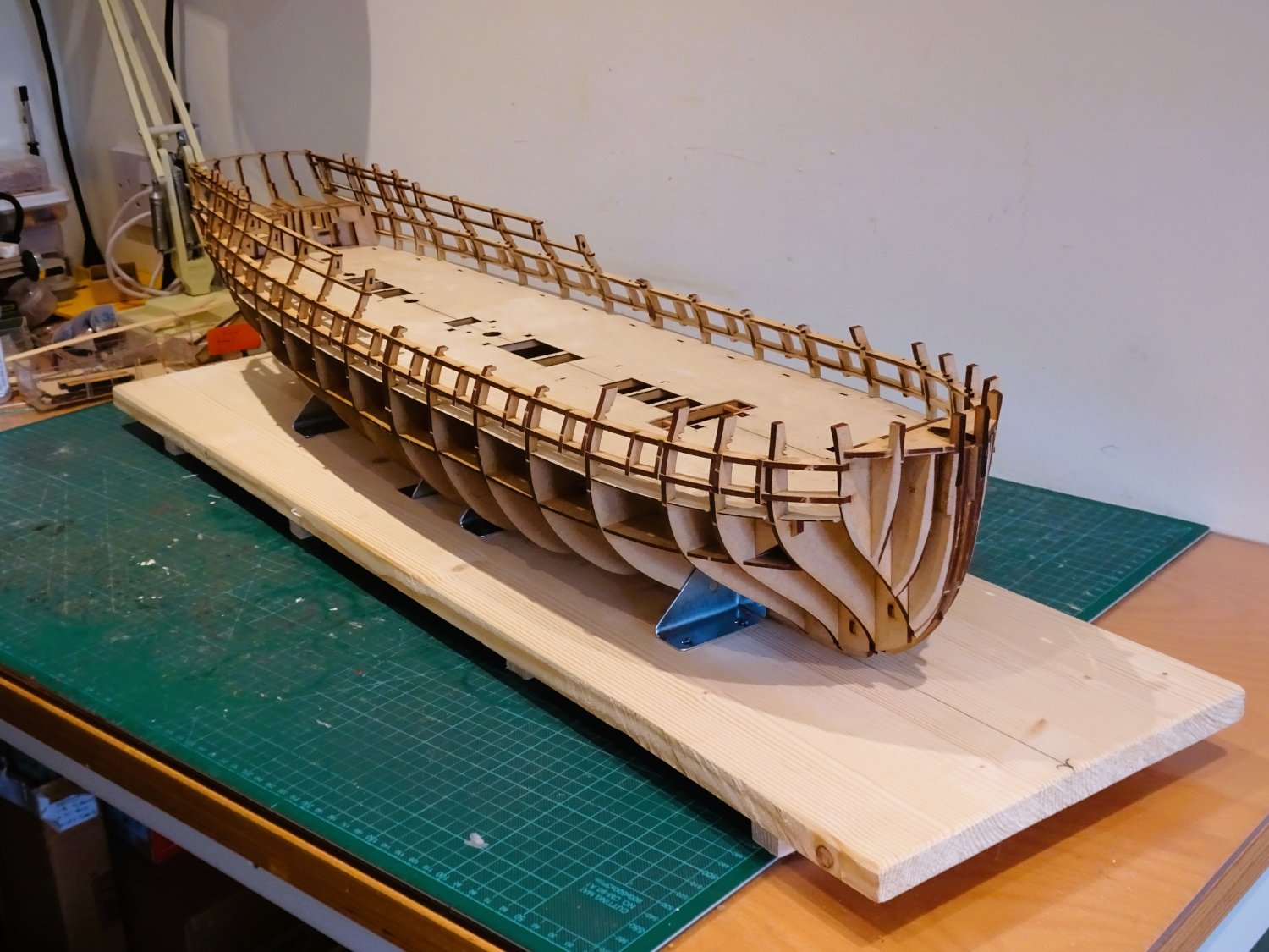
The board is firstly configured for securing the false keel, but will later be modified to hold the keel, full hull, stem and stern posts.
0527

0529
Simple corner brackets are used for the purpose.
I spoke in an earlier post about getting an additional Amati keel clamp to support the long and heavy hull when I require to hold it higher or at angles.

0533
I was a little reluctant to pay out the £50 for a new one but as luck would have it I managed to get one on an e-bay auction for the princely sum of £24. It arrived quickly and is in excellent condition, better than my original.
0536
This should provide the necessary stability for angling the hull when required.
B.E.
19/O3/2023
-
I invariably use heat shrink tubing for iron bands these days.
Get a selection of sizes in black, and cut sections off with a scalpel, job done.
B.E.
- Sizzolo, jpalmer1970, Thukydides and 2 others
-
5
-
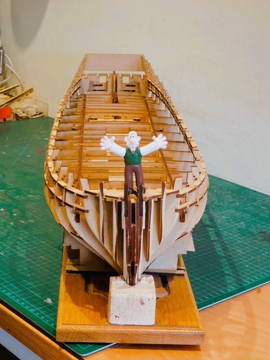
Thank you Kevin, and Ron.
@ Ron - I don't think Wallace has sufficient gravitas to grace the head of such a fine frigate, besides he's a very inventive fellow, where do you think I get my ideas from. He's gone off now for a nice bit of Wensleydale.
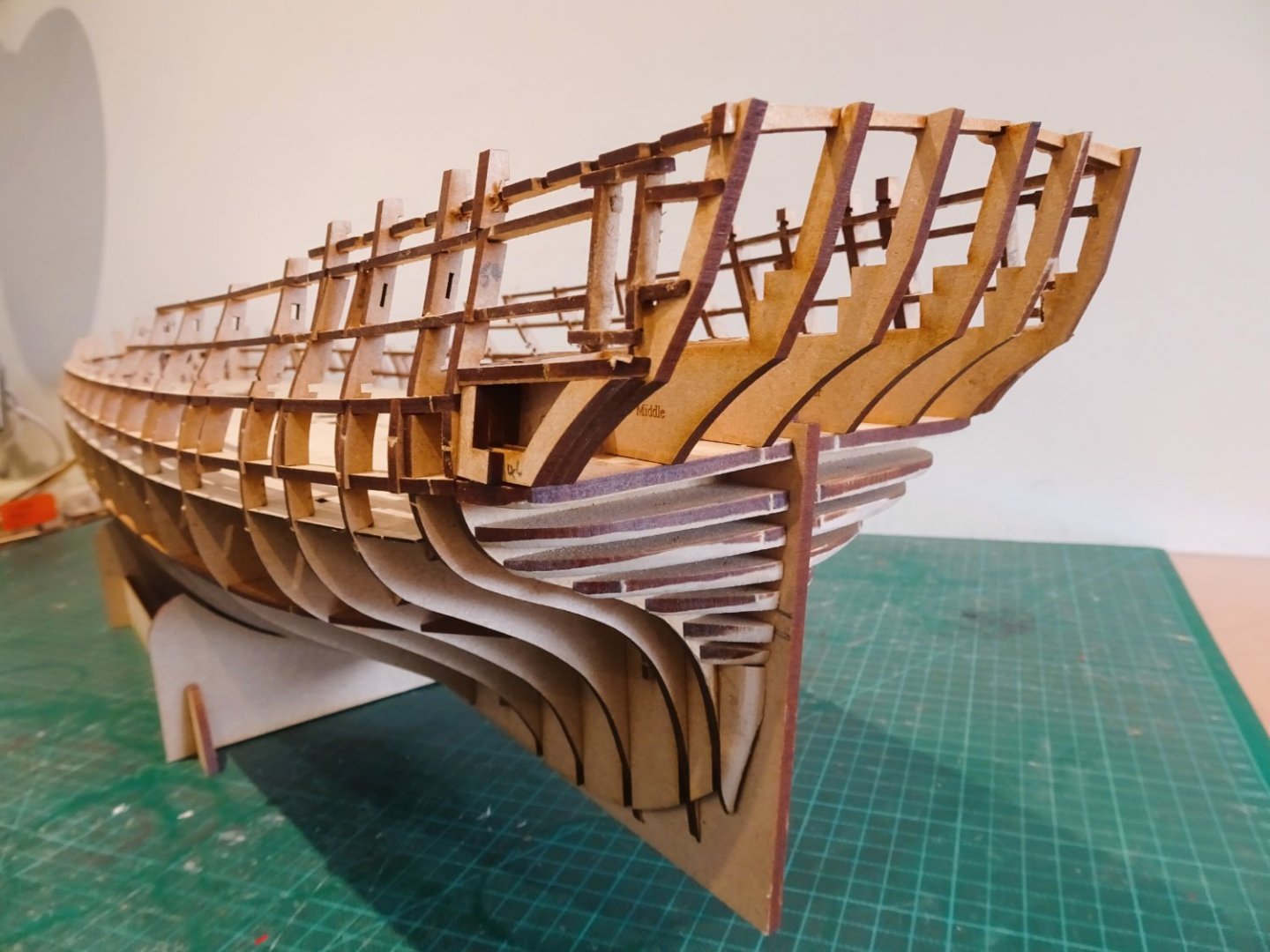
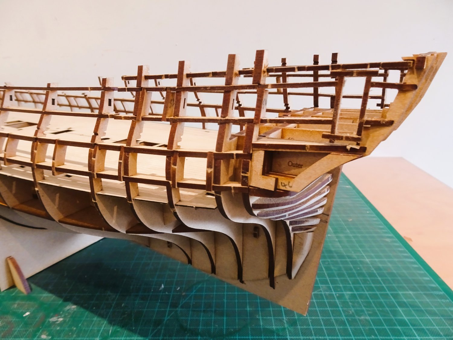
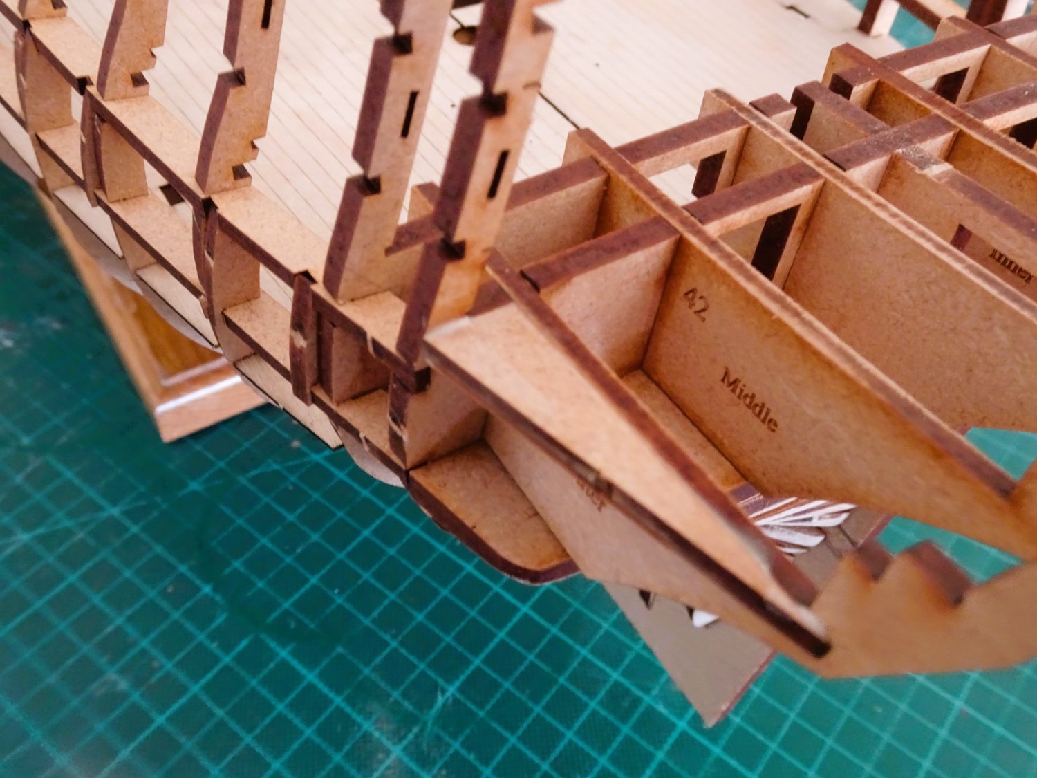
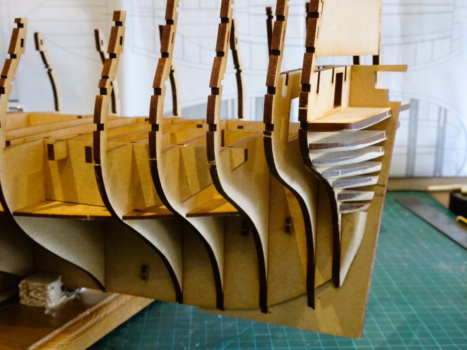
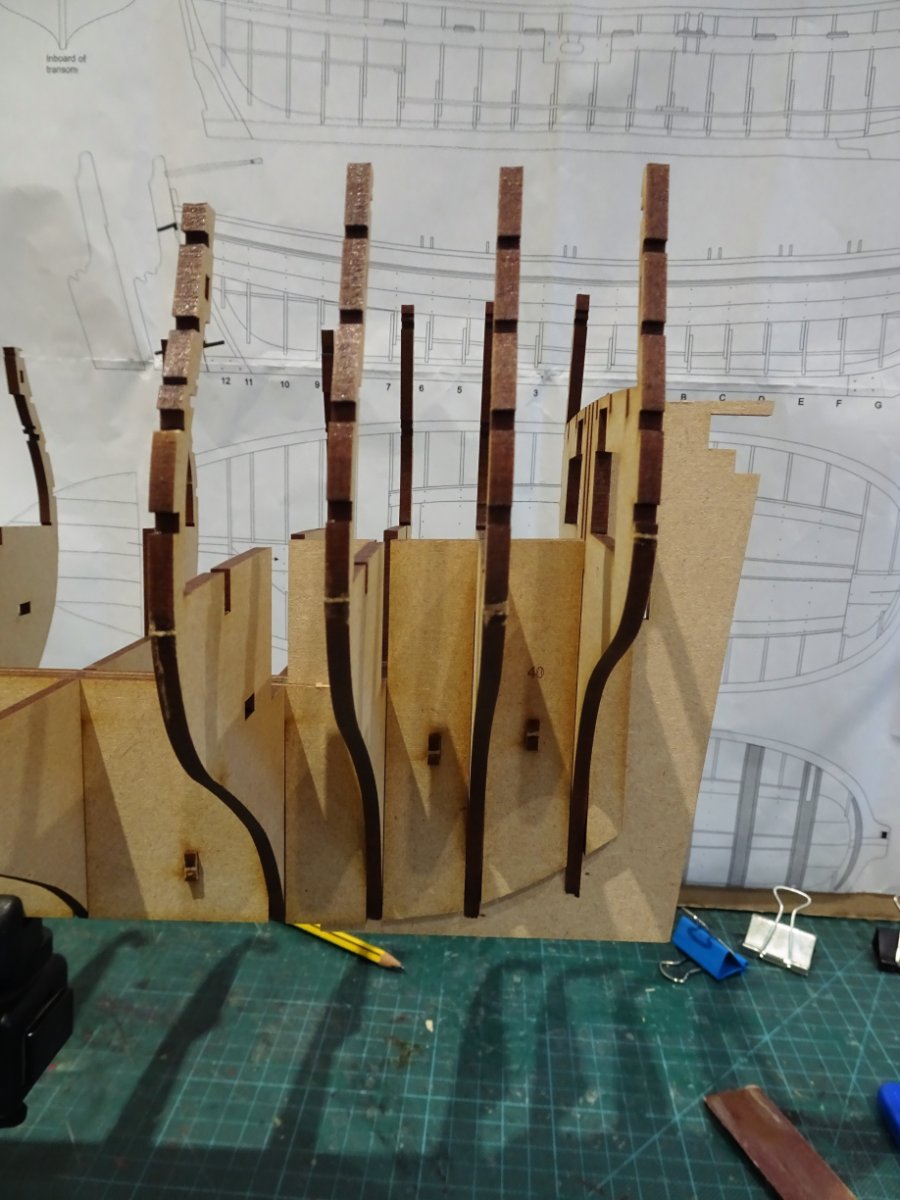
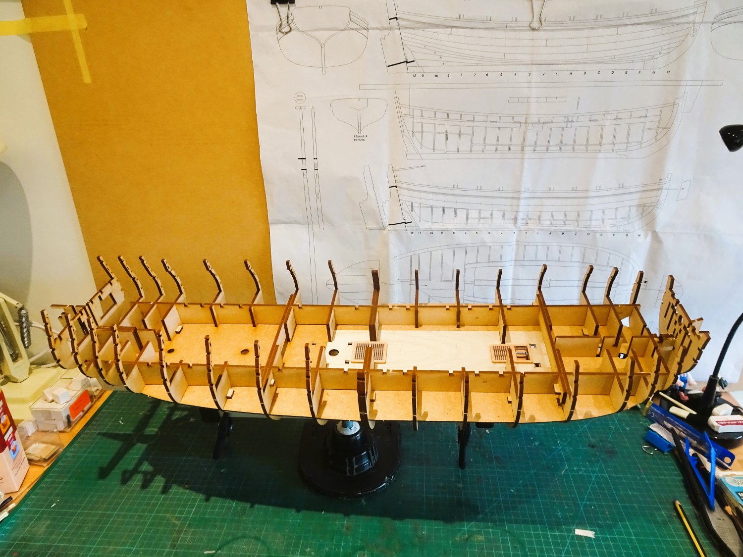
Post Eight
Stern and upperworks Framing
The stern area of the model is way ahead even of Sphinx in terms of authenticity.
With this design Chris has saved me a lot of time and effort modifying the stern interior area to create a realistic great cabin and Quarter galleries.
0508
0510

0507
The framed doorway to the Qtr Galleries, if you want this on Sphinx you have to do it yourself.
This stage is mostly click and fit, and the framework rises with almost minimal effort altho’ some of the parts are delicate and require gentle handling.

0501
In this phase parts #48, fillers for the cabin decking, require some shaping in the form of a slight bevel to match the deck camber, a section of frame 18 is removed, using a micro saw, as with the Qtr gallery door openings. – that’s it!
0506
0513
0515
It is almost incredible that building the hull to this stage has taken me only eight days, but progress will slow now as the less interesting but all important aspect of sanding and fairing beckons.
0517
0514
I think this stage marks the end of the ‘honeymoon’ period of this build. Going forward things will get more complex requiring greater skill levels and attention to finishing.
B.E.
18/03/2023
-
Cheers Rusty 👍
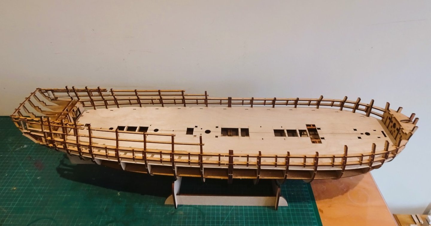
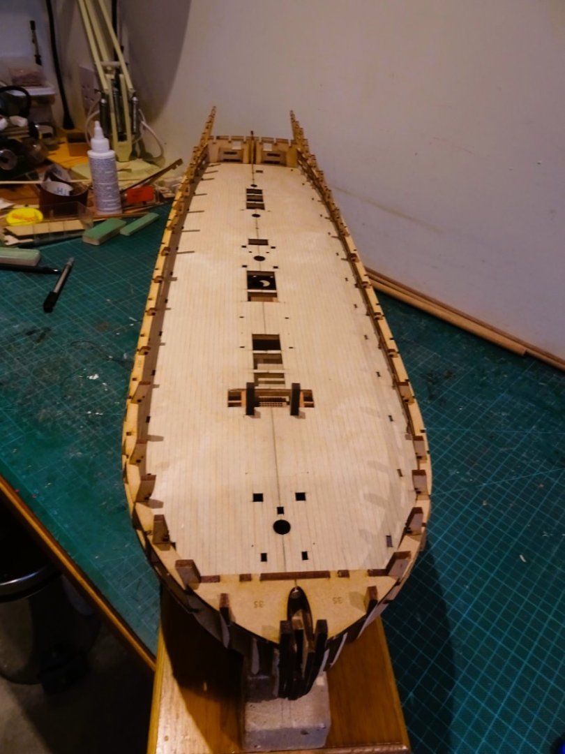
Chapter Seven
Deck fitting.
My initial attempt at dry fitting indicated a mismatch between the two deck halves just shy of 1mm.
0465
0464
This was quite disconcerting as I note that Kevin reported in his log - the main deck went down without any issues - where have I gone wrong, thinks I.😬
The retaining slots were cleaned using an emery board, close attention paid to the seating– but the mismatch remained.

0433
The port side half aligned with the deck beams but the starboard side alignment remained stubbornly a fraction out.

0468
After a lot of faffing around I decided to tweak the slots of the starboard side, taking a sliver off the aft edge of the slots which allowed to section to move forward to align the cut-outs. The depth of the slots around the bow area was also deepened by a sliver which allowed the centre lines to meet without overlap.
0472
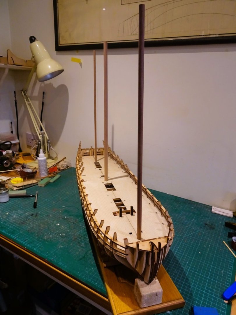
The deck halves now sit down nicely, with the masts and the all-important riding bitts slotting into place.
0479

0480
0484
Happy with the deck fit I can now remove the deck section to reveal the lower deck and Orlop ladderway.
In fitting the deck I perceived that there is a potential weak area around the Mainmast where there is a lack of deck support. I added a beam just aft of the Mainmast to span the gap to provide this.
Satisfied with the result I can now move onto fitting the deck.
Gluing decks can be a fraught exercise, particularly on a deck of this size, where the glue can start to go off before the deck is in place. This is exacerbated if there is any last-minute fumbling in locating the deck.
Certainly in this case, I didn’t think it necessary to glue both deck halves at the same time. Separate halves will reduce the time before glue contact is made.

0488
I glued the Port side first using slightly diluted pva brushed onto the deck beams, the starboard side slipped into place and the deck weighted.
0489
0490

0494
Job done, and moving on…
B.E.
17/03/2023
-
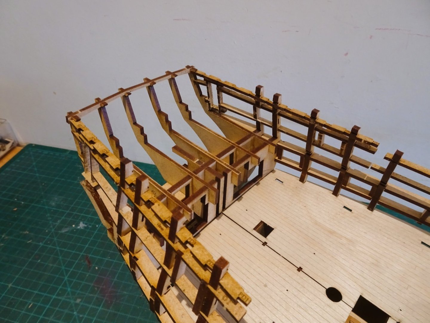
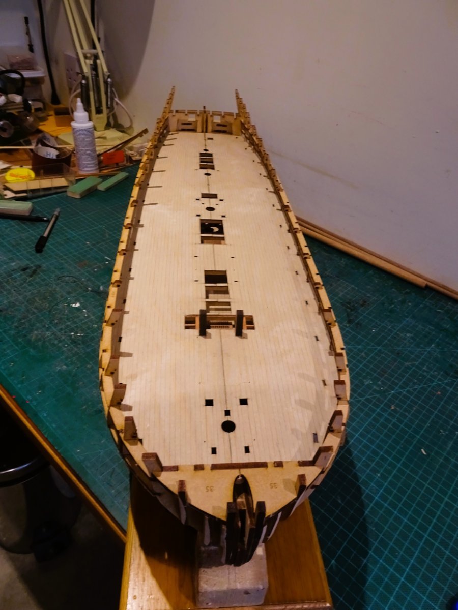
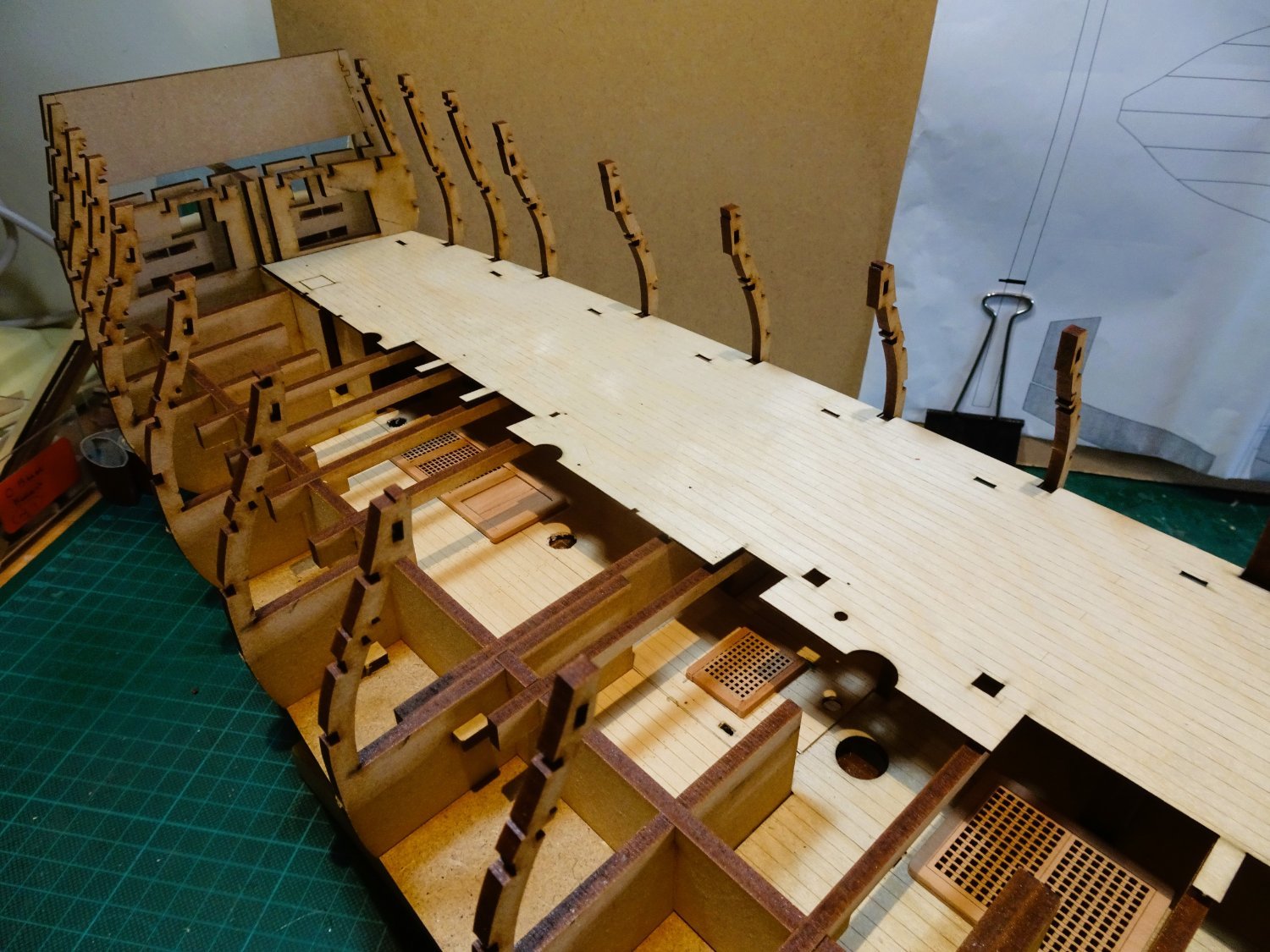
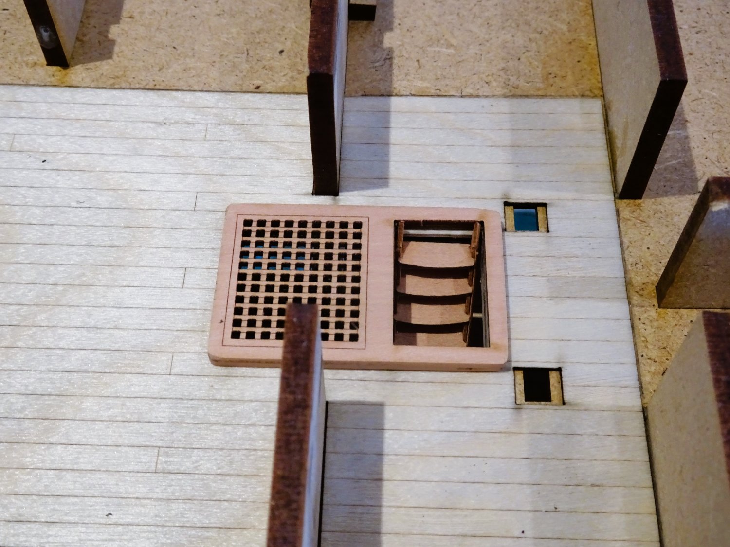
Chapter Six
Modifying the Gundeck
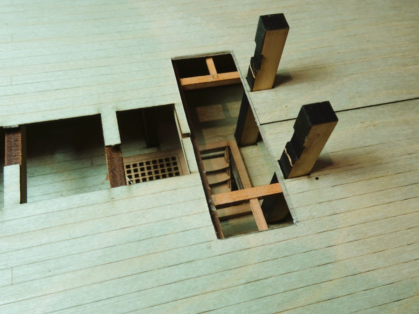
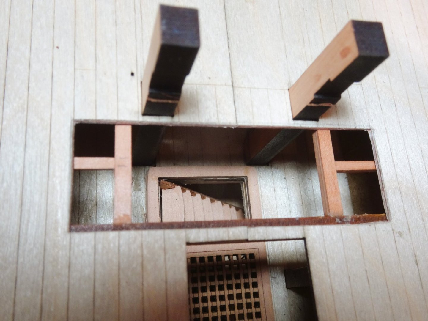
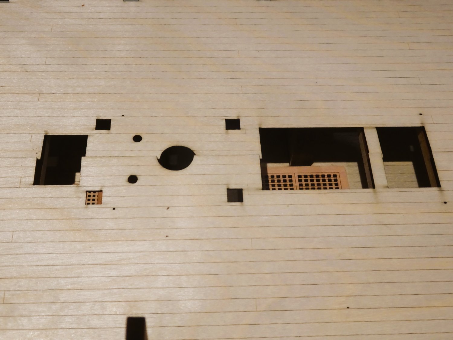
The Gundeck will remain largely intact, but Chris has been kind enough to provide the interesting little feature of the ladderway down to the Orlop.
This will be hidden under the standard arrangement but I want to reveal it. It adds to the illusion of a fully fitted out model.
My idea is to remove that section of the deck between the Fore hatch and the Riding Bitts, but I will need to add carlings.
0444
A template is used to check exactly where and what may be seen.
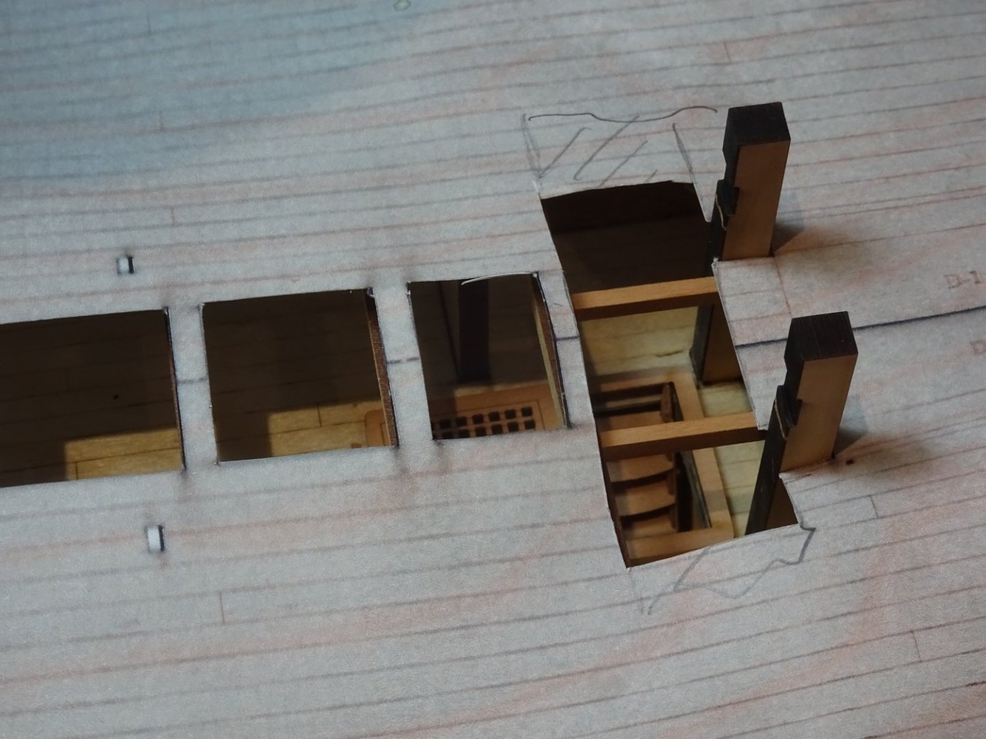
0449
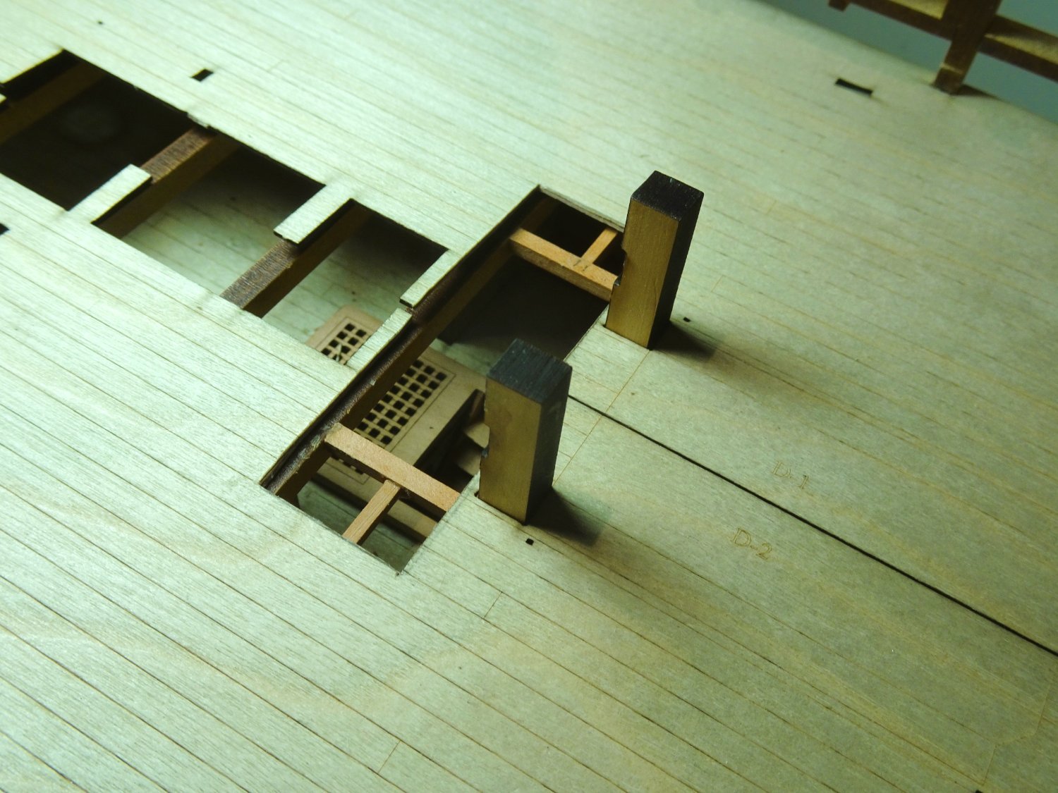
The Riding Bitt standards are test fitted as these will have a direct bearing on where the carlings are placed.
The other thing to consider is avoiding opened up spaces looking like a standard feature.
In the case of the ladderway to the Orlop if I leave a minimal square opening in the Gundeck above, to allow it to be seen, that could look like another hatchway opening.
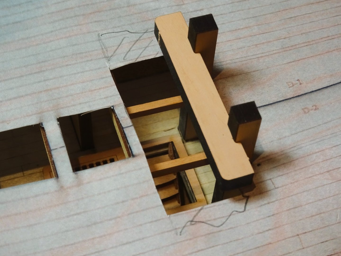
0450
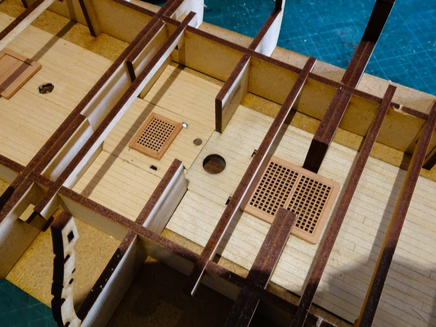
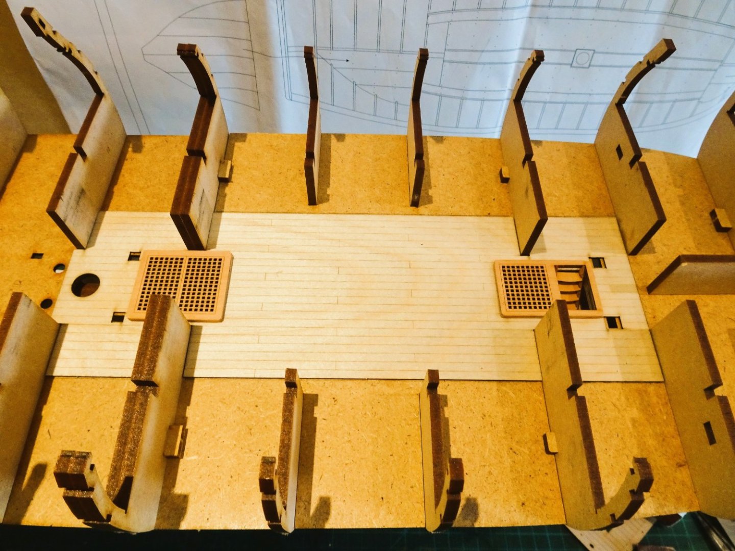
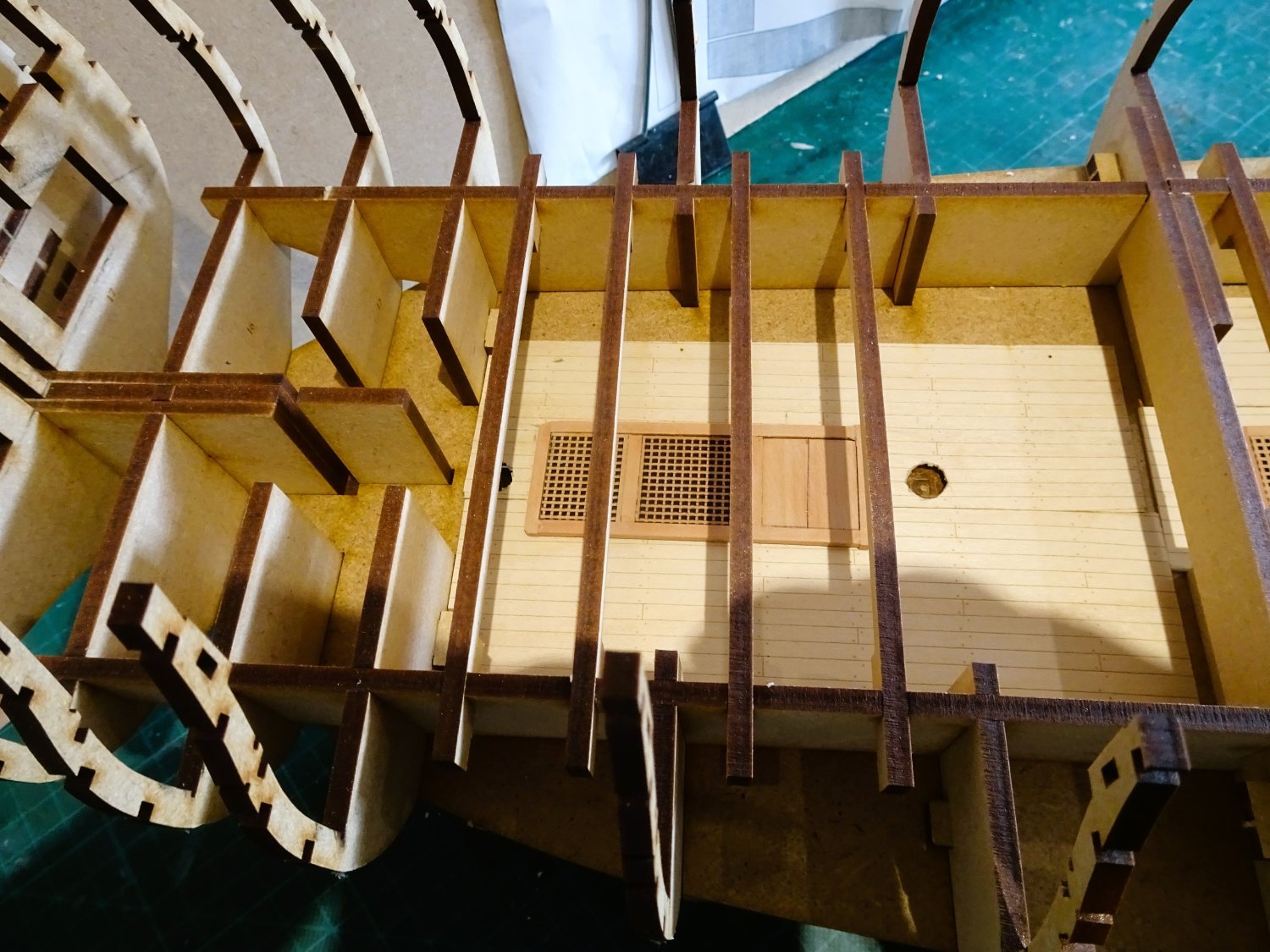
To counter this the unplanked area across the deck is extended and will allow a greater view of the lower deck in this area.
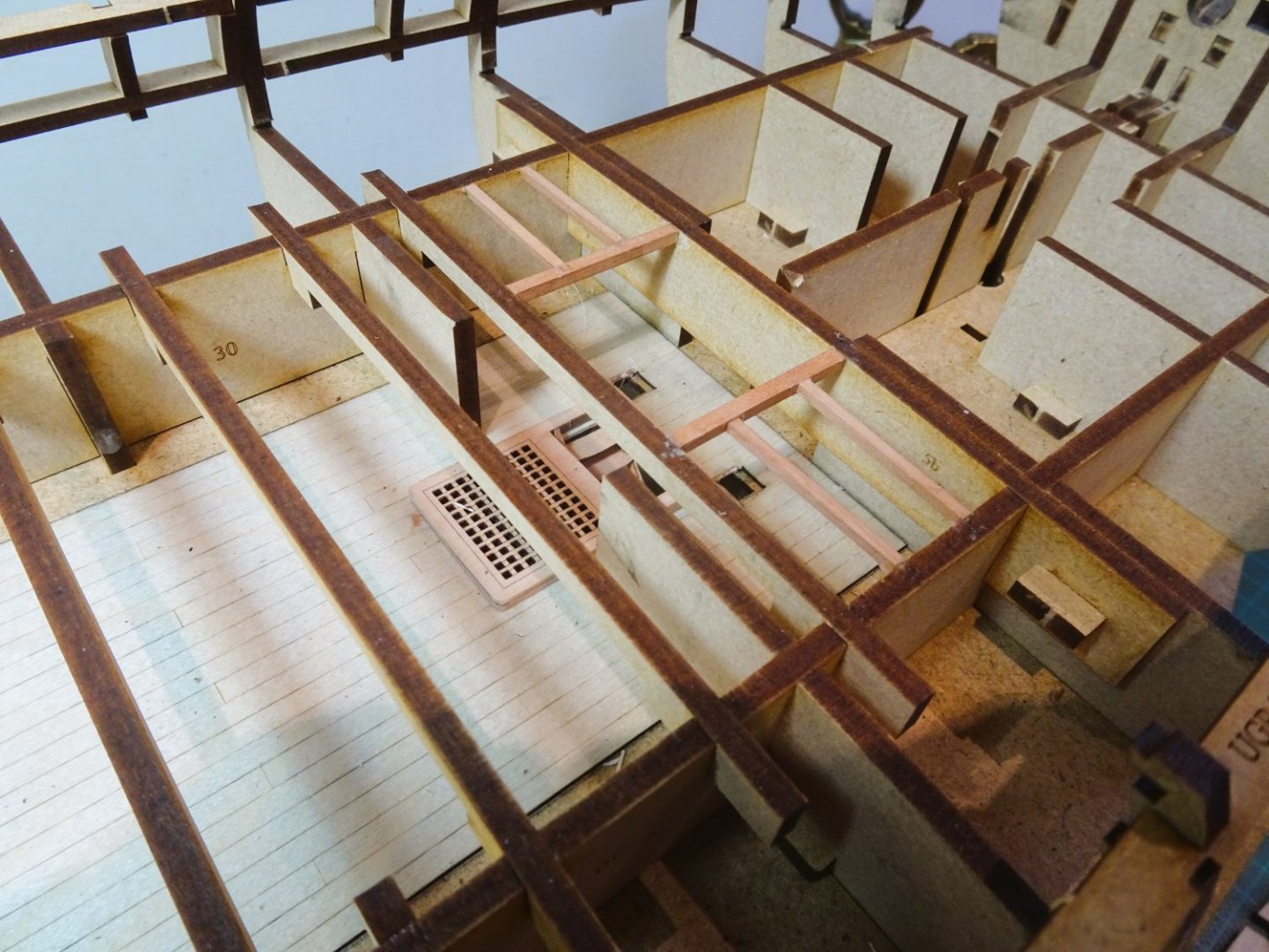
0478
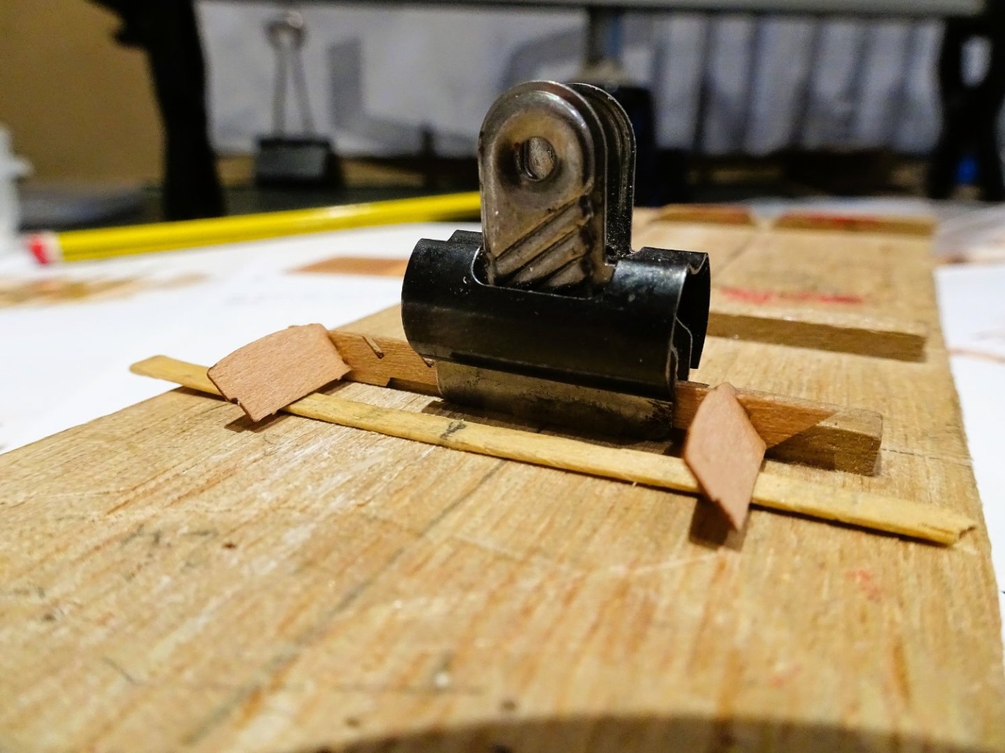
The effect is completed by representations of the carlings and ledges.

0477
3mm x 2.5mm pearwood square stock was used for the carlings, and 2 x2mm for the Ledges.
B.E.
16/03/2023
-
-
Thank you Ron, Kevin, Marc, and Capt. Birdseye.
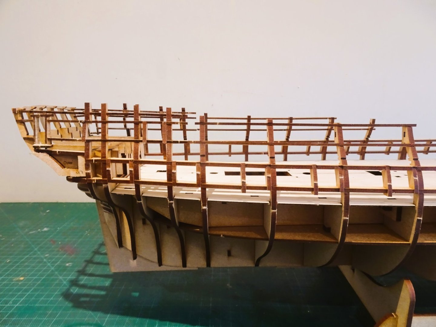
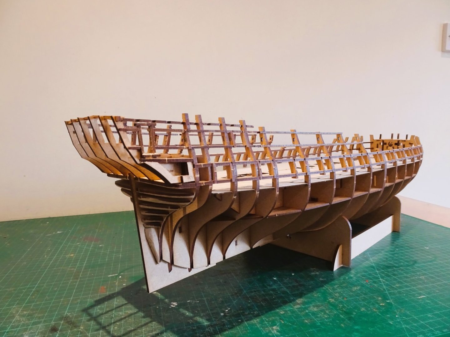
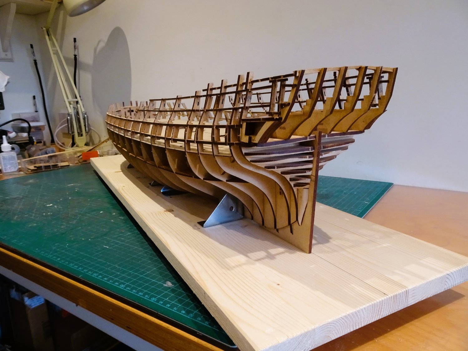
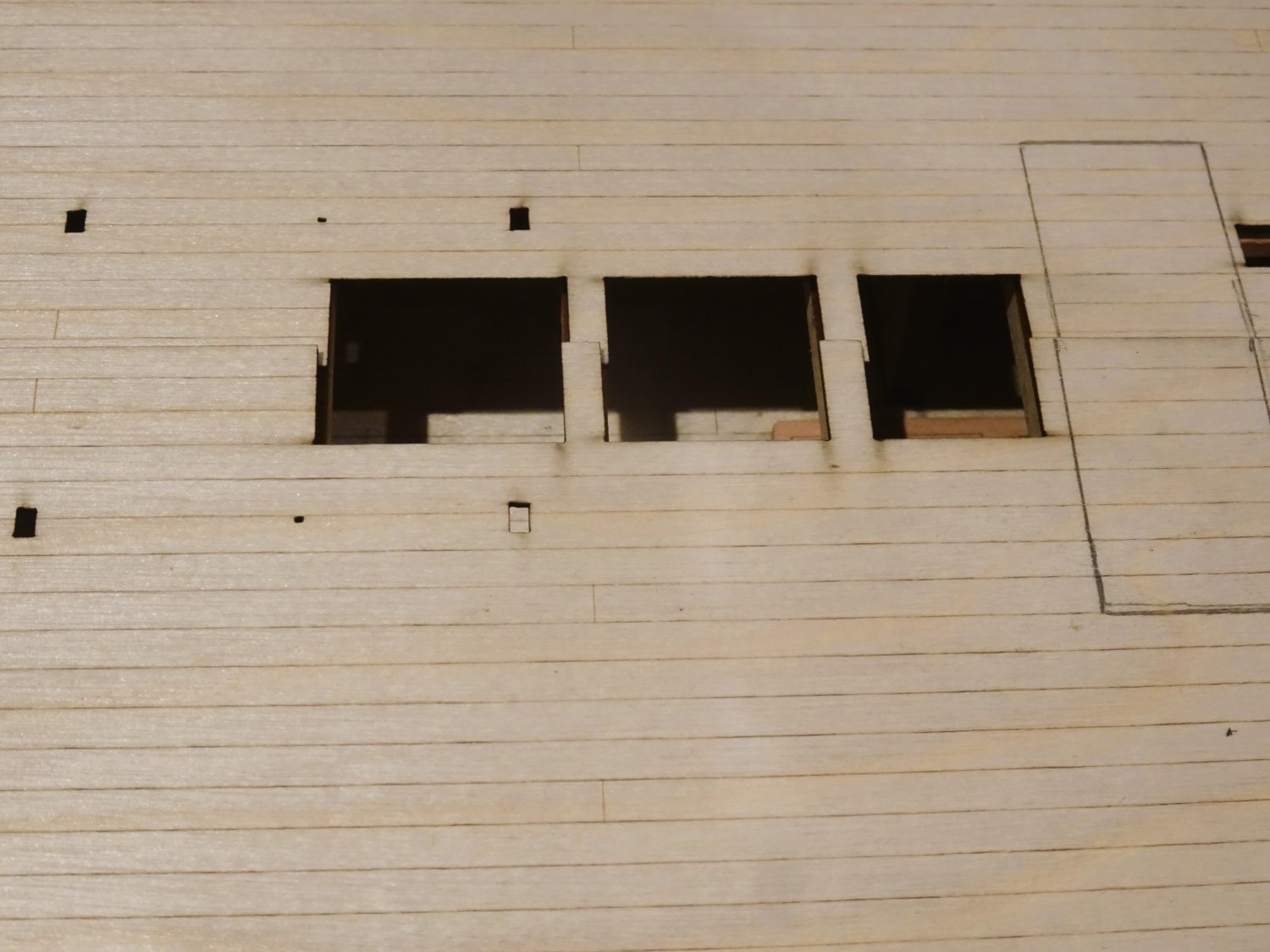
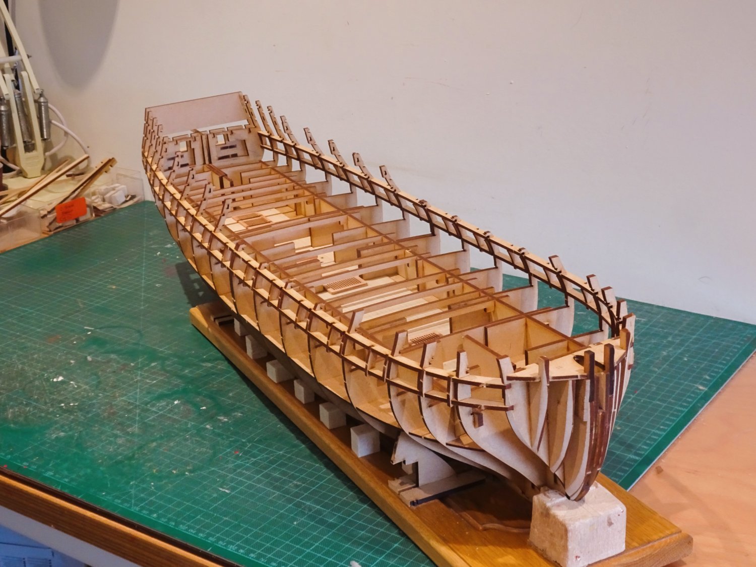
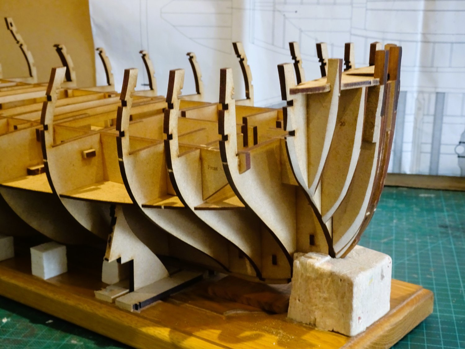
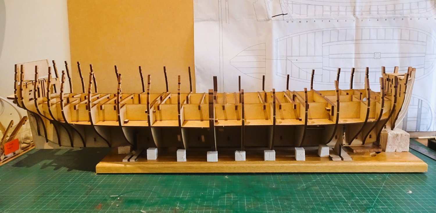
Chapter five
Framing the Gunports.
This is an ingenious method devised by Chris that gives a nod to the Plank on Frame method and removes all that testy business of cutting ports into a hull.
The longitudinal stringers that form the top and bottom of the gunports are now fitted.
0454
I fitted the rear gunport strips from the stern forward, I found it easier to locate the two aftermost slots fully into the bulkheads.

0452
These are followed by vertical risers that complete the port framing. They are position specific so care has to be taken in their fitting.
0453
The parts fit together beautifully, and at this stage of the build it is rather like doing a 3-d jigsaw puzzle, but without the puzzle element.

0457
I’m loving the look of her even at this stage, I think you will all agree she is an impressive sight.
Chris must be well pleased with the fruits of his labour.
The next stage is fitting the gundeck, but at this point I am going ‘off piste’, as I have some modifications to work out given the ‘Navy Board’ style of my build.
B.E.
15/03/2023
-
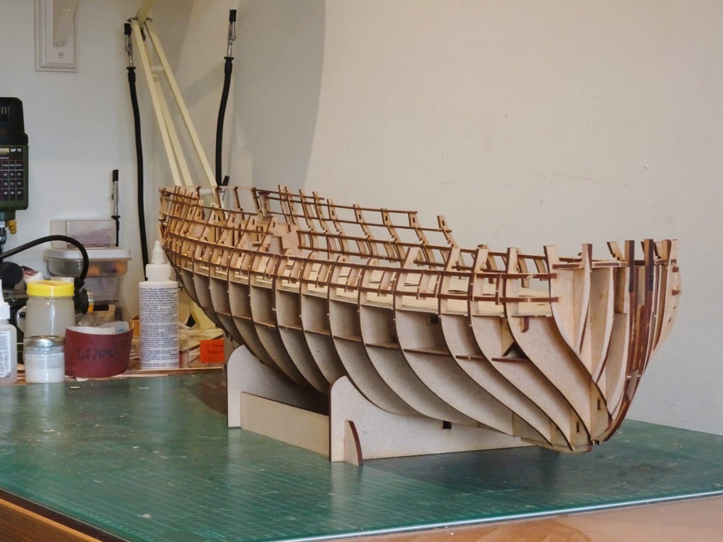
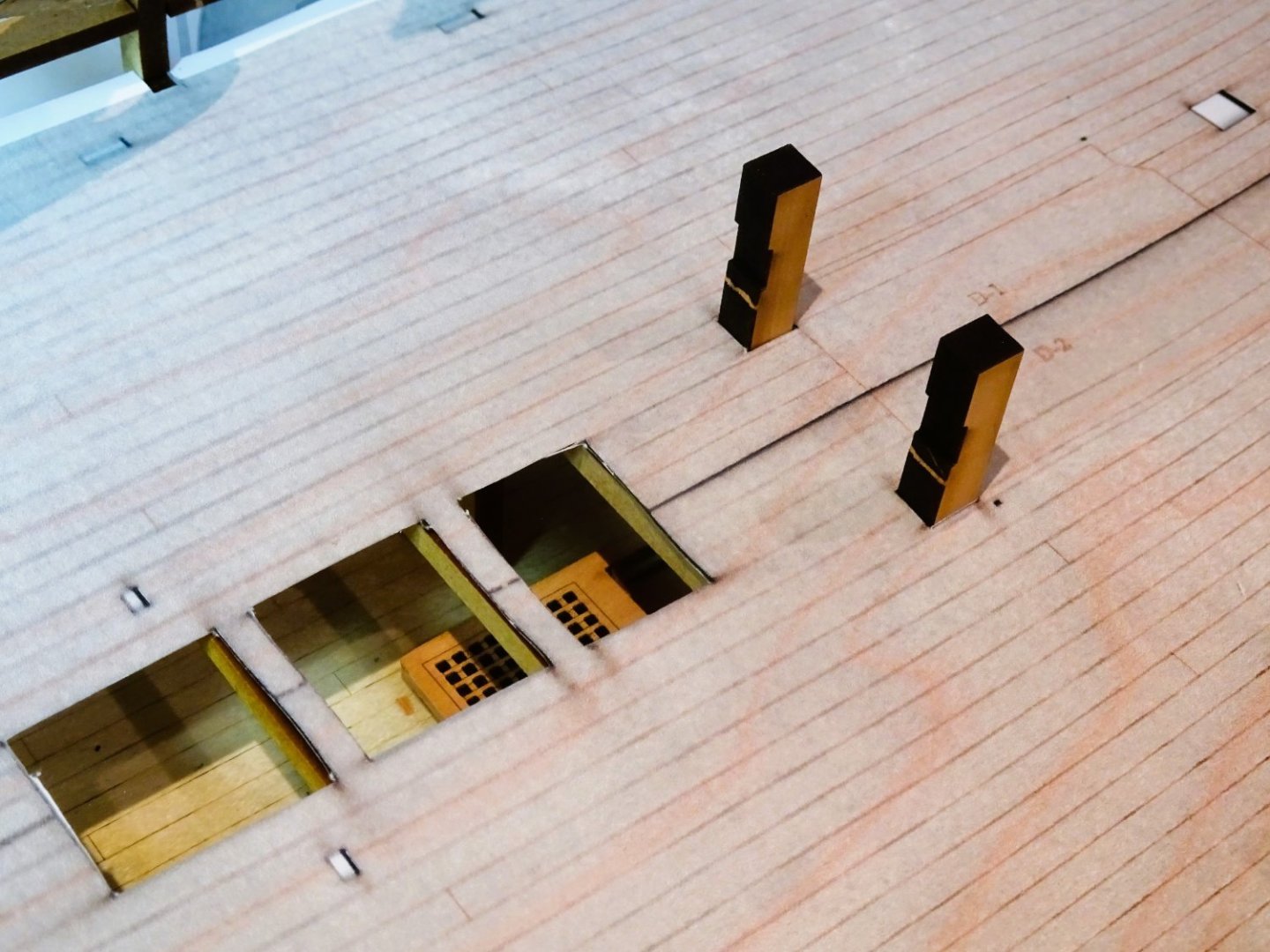
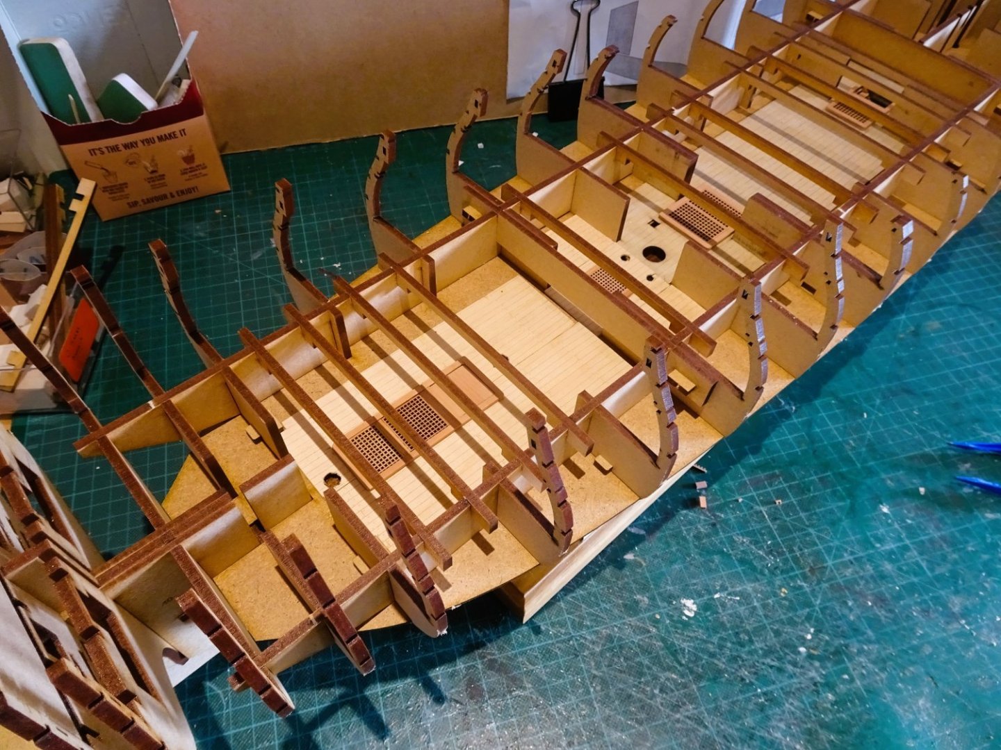
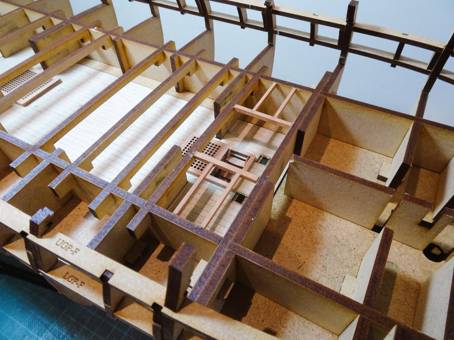
Chapter Four
What lies beneath.
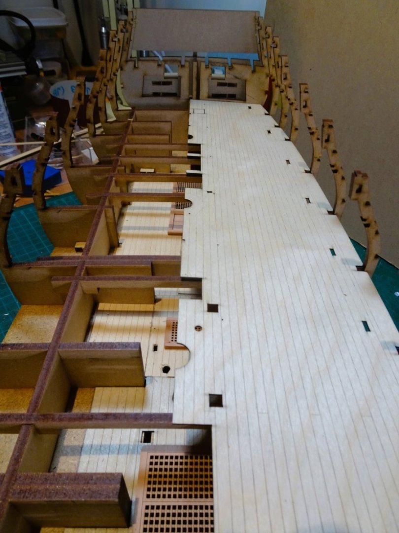
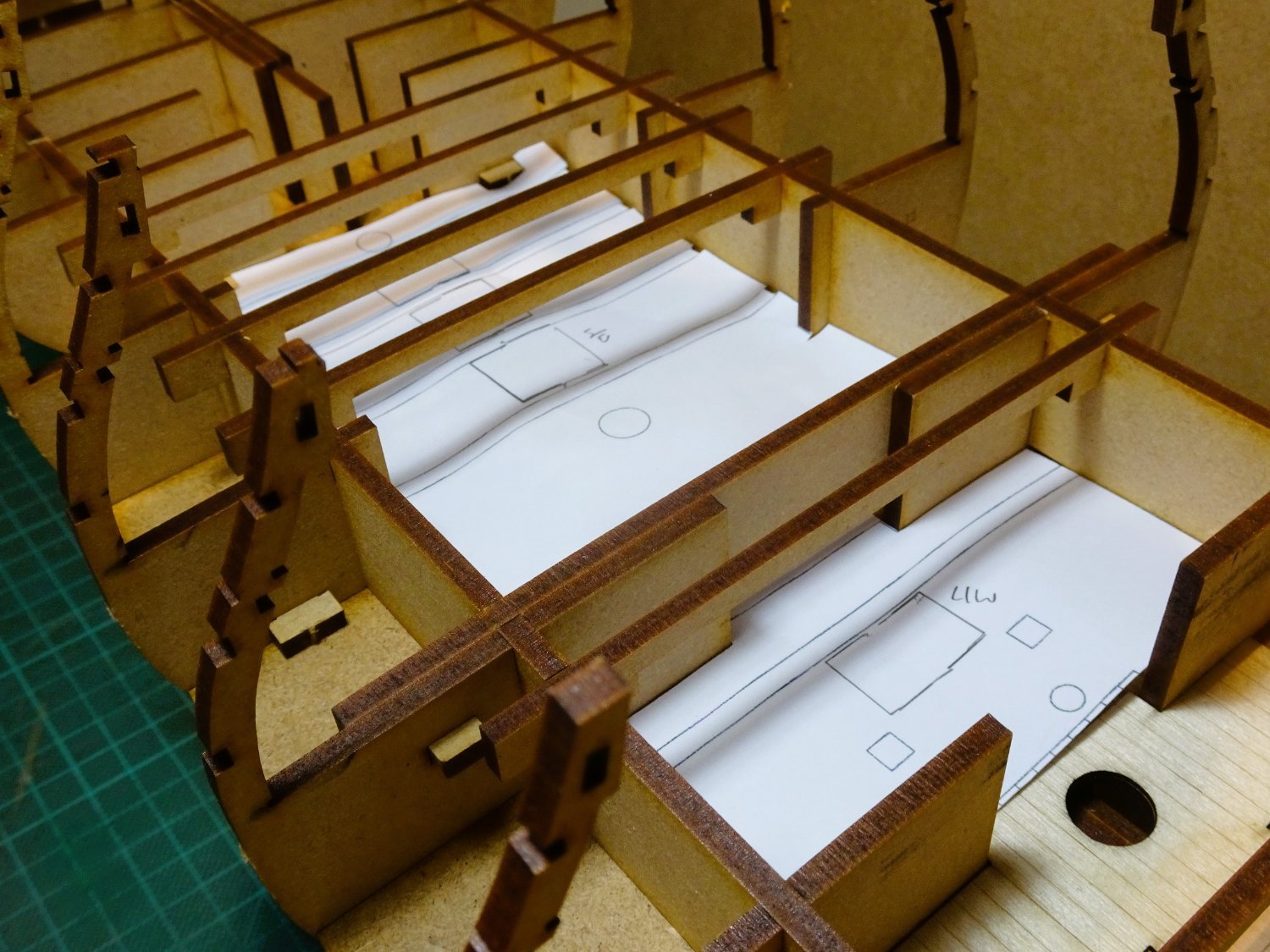
Before the Upper (gundeck) is fitted I need to establish what may be seen below on the Lower deck.
This is relevant on my build as the deck will be open to maximum view.
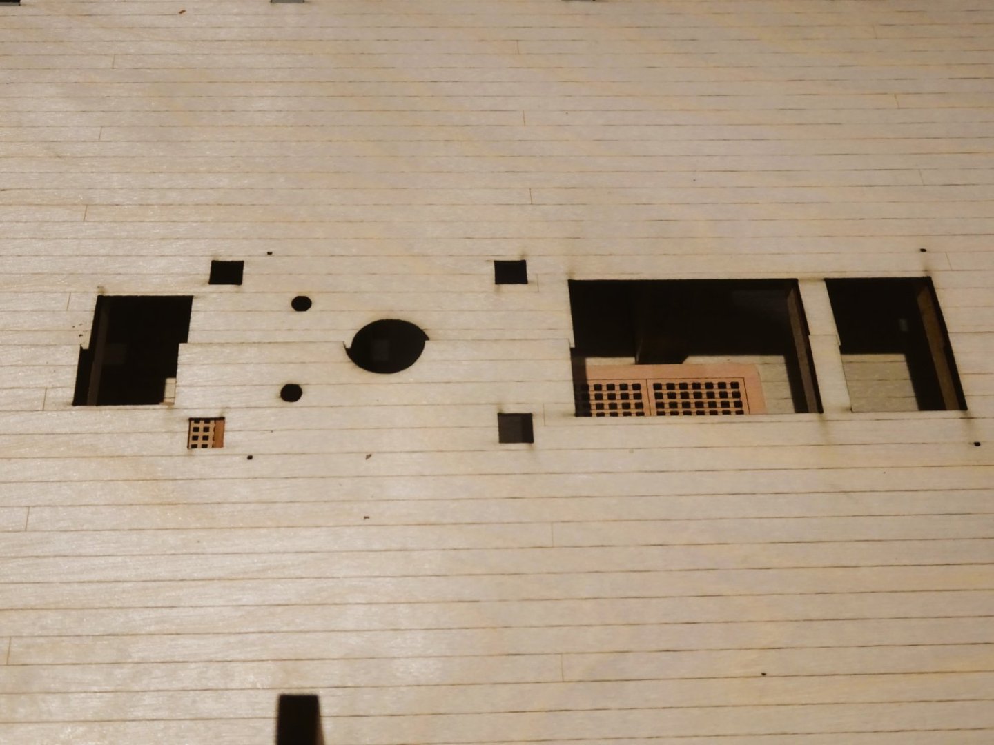
Planking and detail provision is made for the Lower deck between the Fore hatchway and the Mainmast, but aft of the Mainmast there are also ladderways and hatches down to the lower deck which just may be visible should I choose to leave the gratings off the hatchways.

0427
Template taken from the plans for the section aft of the Mainmast.

0430
0431
0428

0429
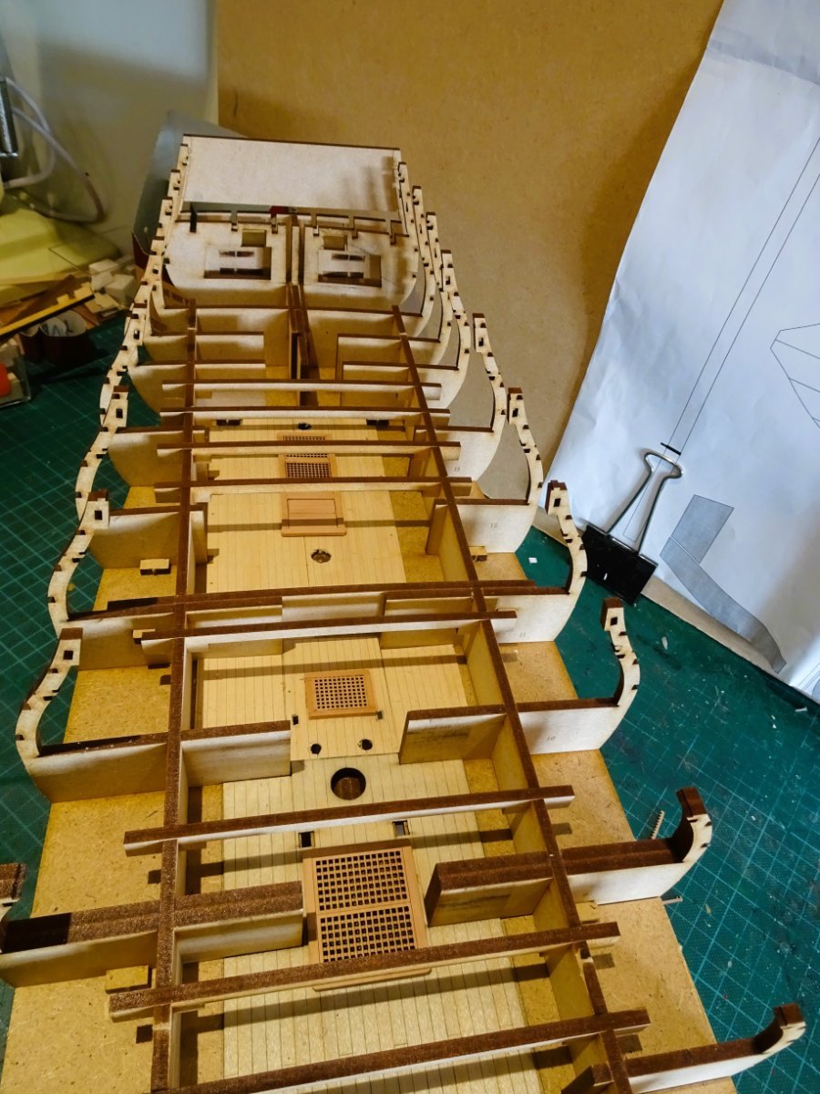
These additional areas of the lower deck are planked using cannibalised maple deck sections left over from my Sphinx build, and I knocked up grating sets that are pretty much the same as the Gundeck arrangement.
0433

0434
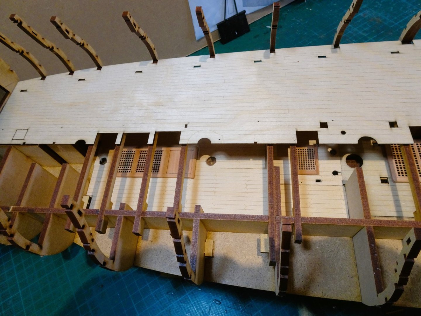
0435
Temporary rough fitting of the gundeck gives a sense of what may be glimpsed on the lower deck.
This will I hope give the illusion of a fitted out Lower deck limited as the view will probably be.
B.E.
13/03/2023
-
You put me to shame Alistair, better not let my wife see your work space😬
B.E.
-
Thank you, Alistair, for your kind words, glad my old Pegasus log is still providing some use.
Yes, that is Bluebell, made back in the 1990’s from a Matchbox Kit with aftermarket additions. I loved those corvette kits so much I built it again as Snowberry (A Revell issue) with more modifications, but that one is cased.
I like the hooded planks on the QD adds a load of interest, and those replacement headworks are a vast improvement on the kit issue.
Enjoying your resurrected build.
Regards,
B.E.
-
Coming along very nicely Kevin, she looks impressive even at this stage.
B.E.
- Old Collingwood, Kevin, hollowneck and 6 others
-
9
-
If that's a reference to my post Jim, I'm not having a go at you, simply record it to save people time in sifting thro' all the sheets to find the part, as I did initially, and as something highlighted for future editIons of the manual.
This was a massive enterprise and I commend your efforts and build, sorry if I've upset you.
Regards,
B.E.
- Mr Whippy and hollowneck
-
2
-
Great to see again Alistair, she is a beautiful model and deserves to be finished.
With a view to the coppering finish, I'm off to make friends with the horses across the lane.😉
B.E.
- CiscoH, hollowneck and Ryland Craze
-
3
-
Thanks Alistair, I don't know about longer UK hours, I suspect the fact I'm long retired has more to do with it, coupled with the fact I've now given up Golf. 😊
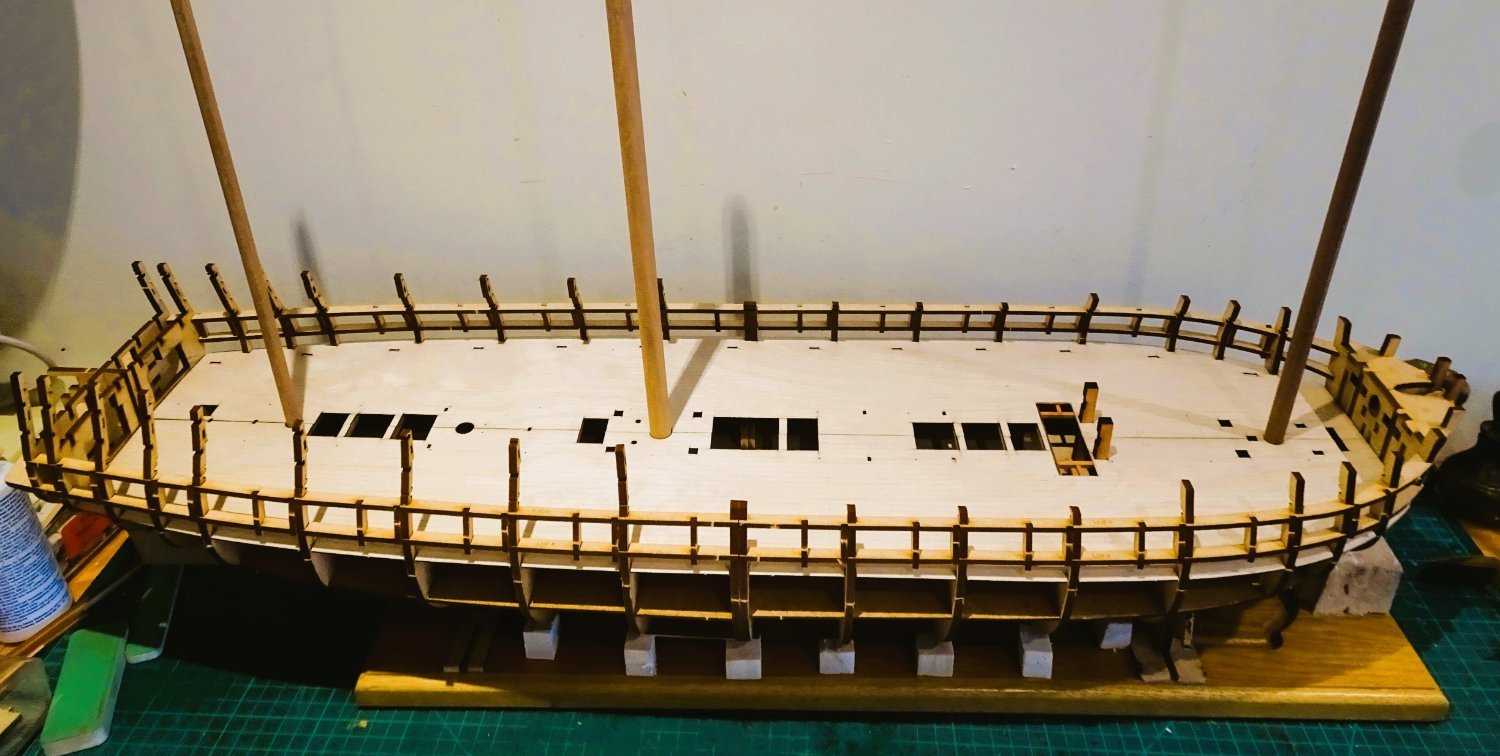
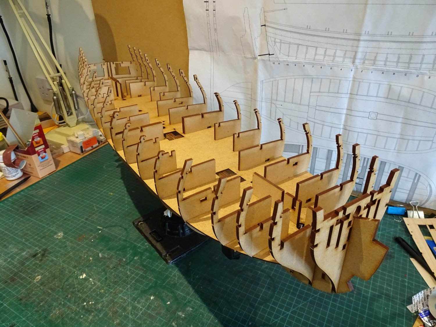
Chapter Three
The Assembly continues.
I pick up this stage by adding the deck beams for the Upper deck and will finish with the bow and stern assemblies.
Twelve beams are required that simply slot into the longitudinal braces (part30) There are three spares.
Note: These are located on the 4mm mdf sheets, not 3mm as indicated.
0415
My old Sphinx build board is re-figured for this early build stage.
The bow parts that build up the round are now assembled.
Note: Part#34 is located on the 3mm mdf sheet, not 4mm as indicated.
I followed the indicated sequence of fitting the bow extension pieces with Bulkhead 1 fitted to the keel, taking care not to get glue on the keel.
I then struggled to remove the bally thing from the Keel, and I began to worry that I may break something trying to free the bow section. I used a piece of dowel thro’ the Bowsprit opening to act as a lever to ease the part out, combined with pressure on bulkhead 2 and the extension pieces that fit over it.
Nevertheless, it was a bit of an anxious moment.
The final parts were then added.
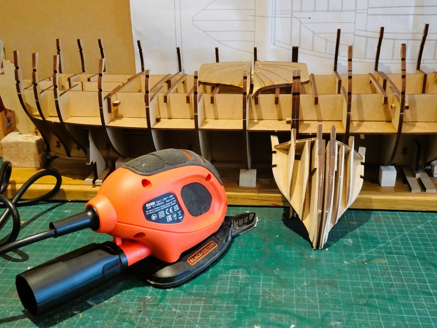
I read in Jim’s log that Chris had recommended a palm sander to do the fairing, given the size of this beast.
As a confirmed toolaholic, I followed Jim’s lead and got myself a B&D Mouse. (one of those sundries I referred to in Chapter 1.)

0410
I’ve never been a fan of power tools for delicate work on models, I don’t trust myself, but I thought I’d give it a go.
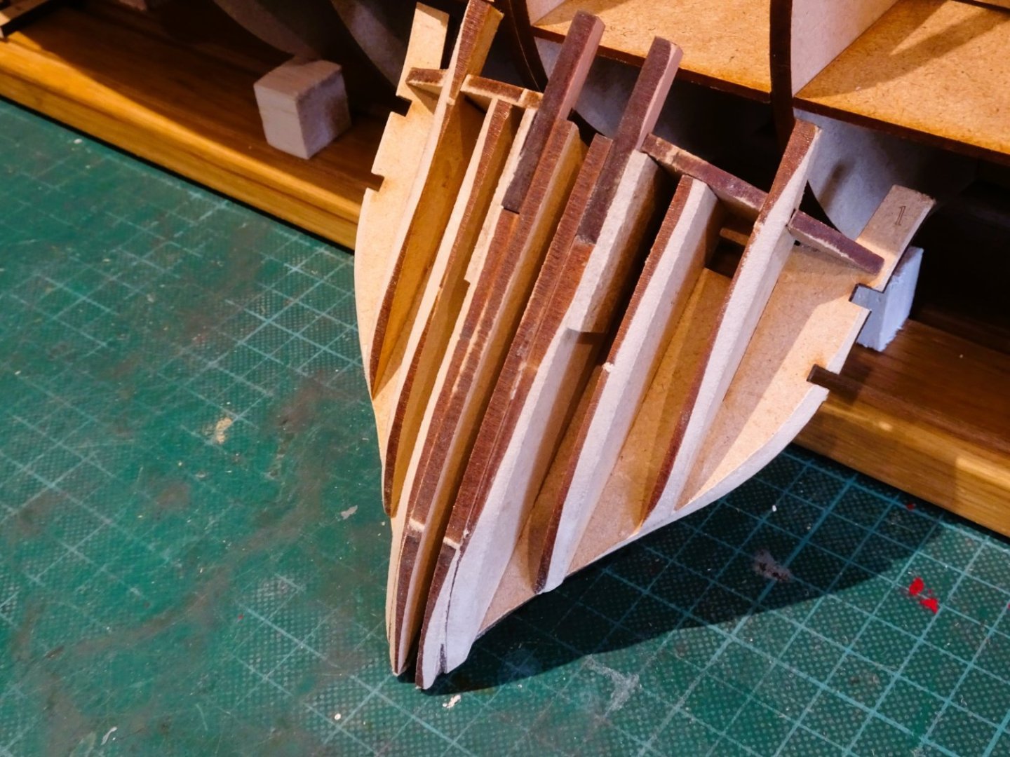
Initial fairing of the bow section seemed a good place to start, and I was pleasantly surprised.
The mouse sits easily in the hand, and with the finger extension attached, there is no feeling of it running away and taking too much off too quickly.
The finger extension which acts like a sanding stick, runs across three of the bow extensions, and I think it will prove useful to reduce the amount of hand sanding required in the fairing.
0411
This is about as much as I felt comfortable taking off with the section off the model.

0424
The bow section was then glued into place.
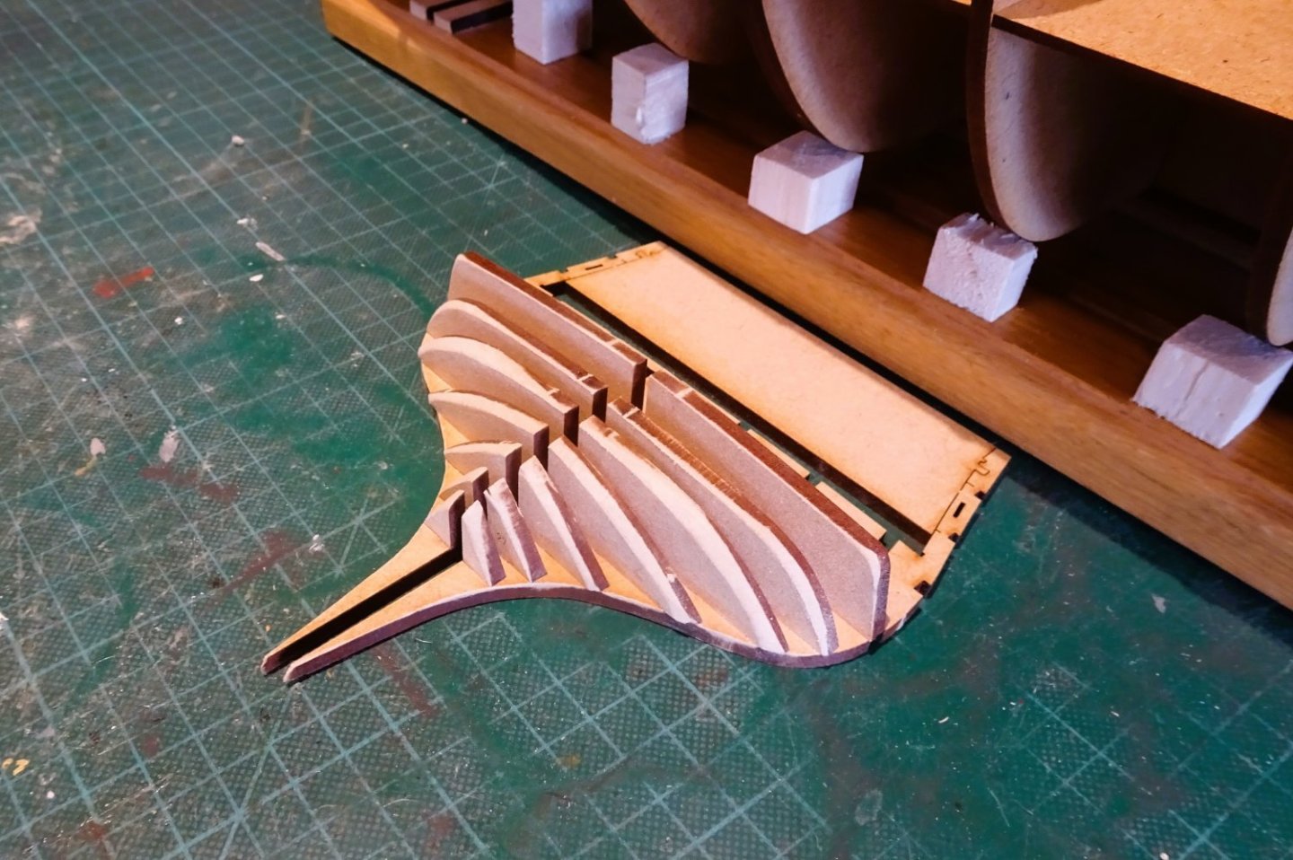
Same procedure with the stern section.
0418
0420
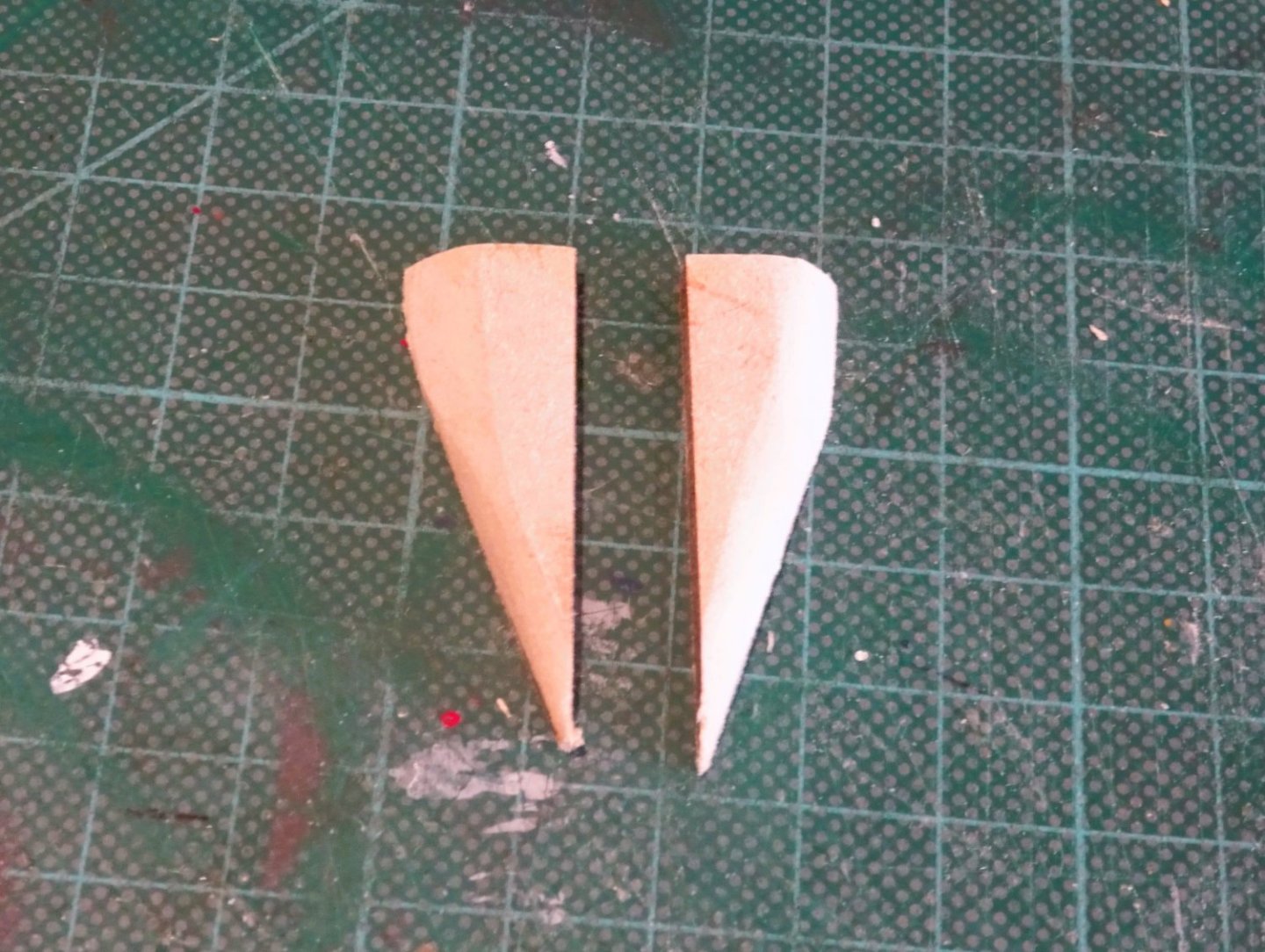
The final section (parts 29) are pre-shaped before attaching to the keel.

0422
Completion of the fairing will be done on the model.

0425
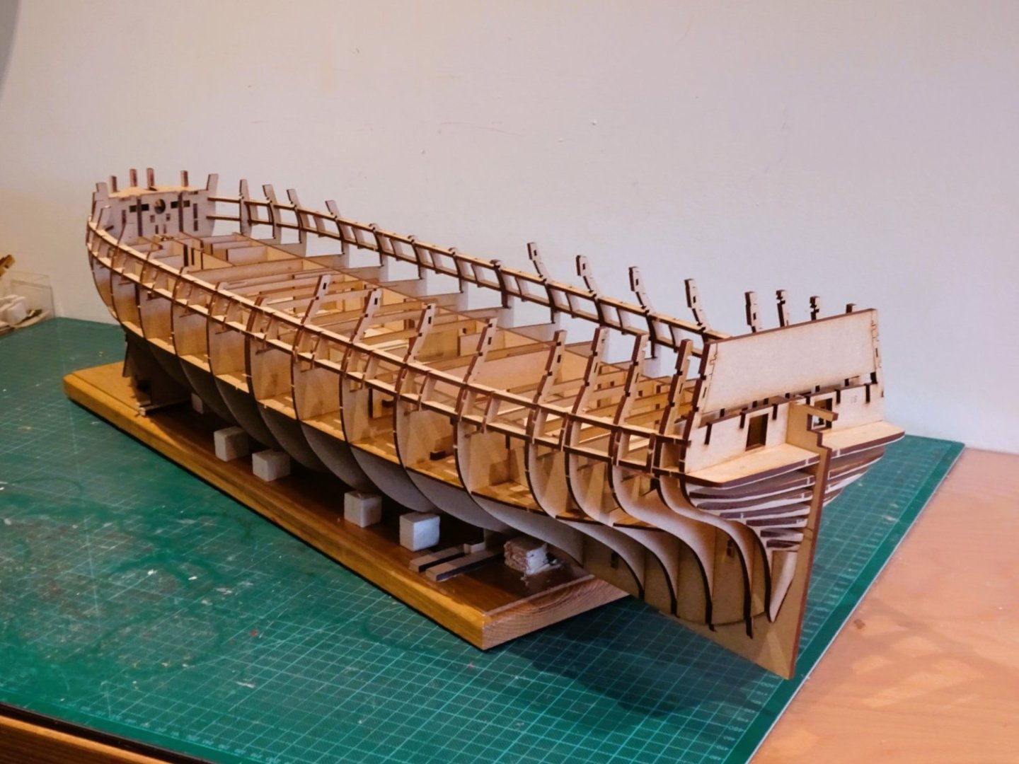
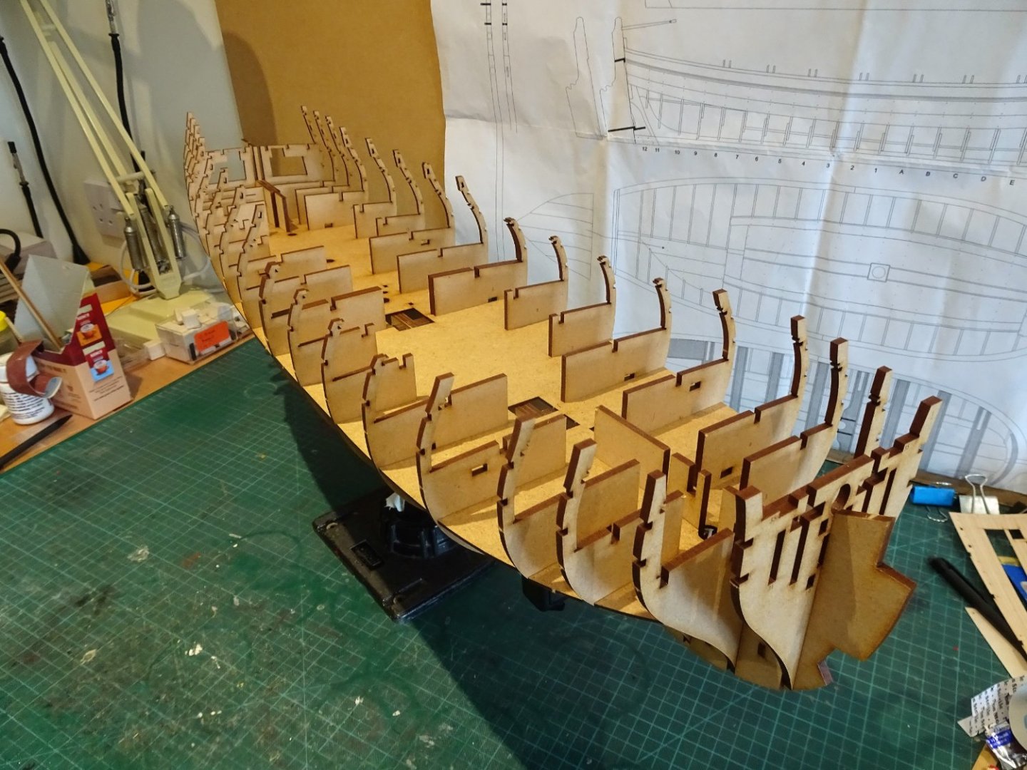
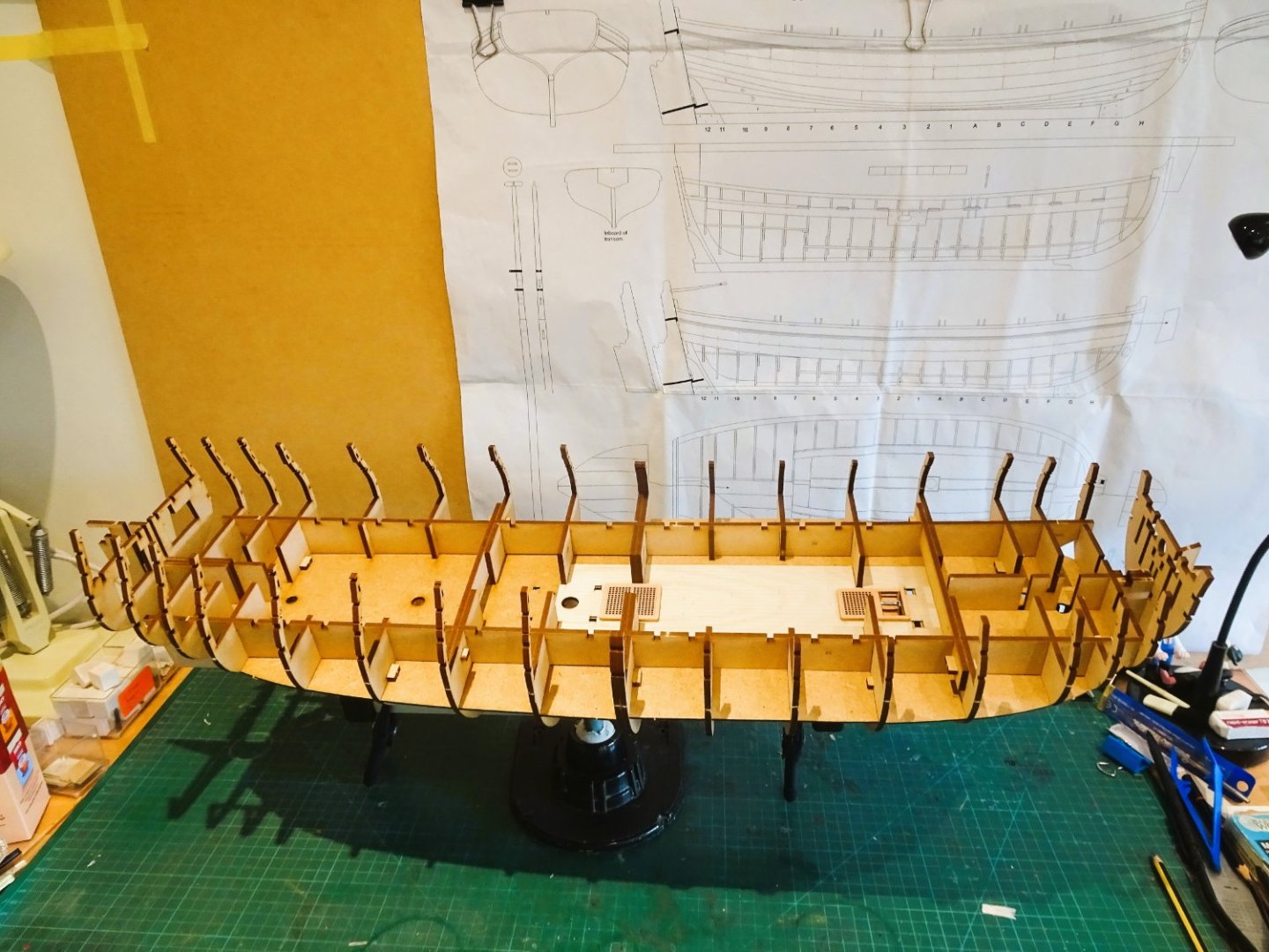
All the bulkheads are now attached and she’s starting to get heavy.
I’m thinking of adding lifting handles to the build board ends.

0412
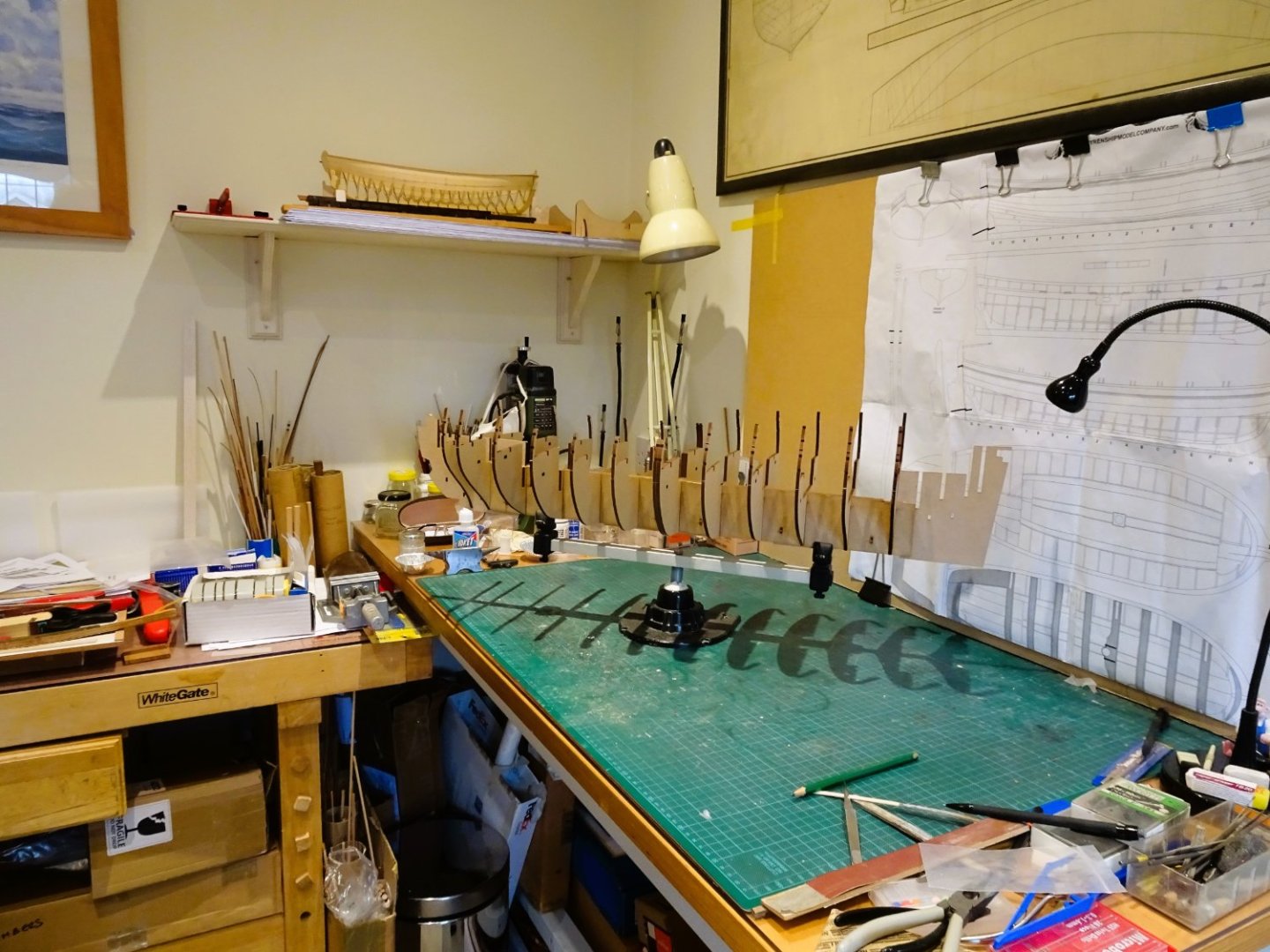
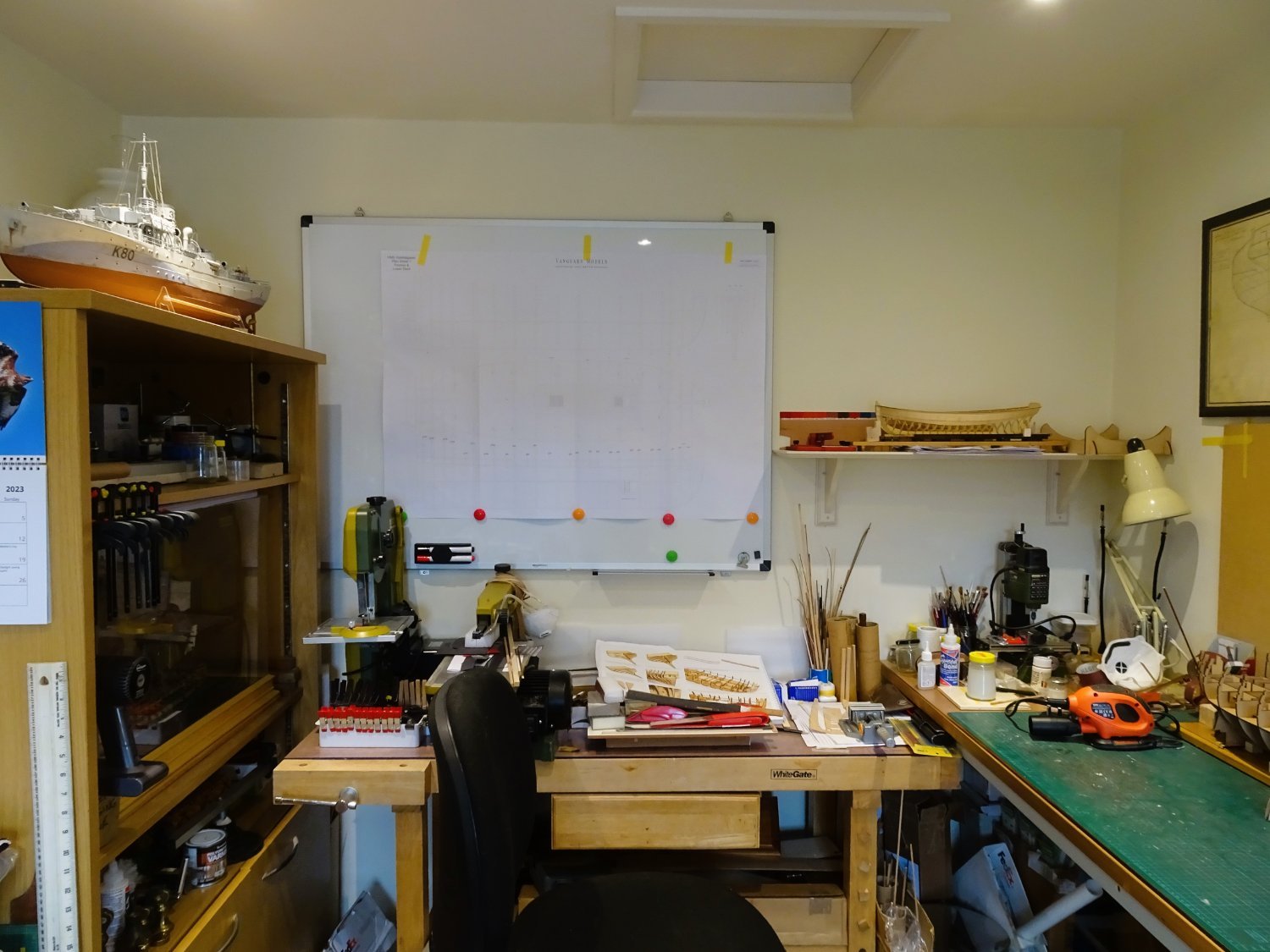
I have also invested in a white board to display Chris’s beautifully drawn plans, I was struggling to find somewhere to open them out, and this Amazon basic board fits the bill.
B.E.
12/03/2023
- JpR62, mtaylor, realworkingsailor and 14 others
-
17
-
Thanks Glenn and Ron,
I usually have three build boards for larger projects such as Sphinx/ Indy each one specific to a particular stage of a build.
I find the Amati clamp very useful where I want a specific angle, or a bit of height but wouldn't trust the single one for Indy, she's too heavy and long.
At the moment I'm using my old Sphinx board bashed to accommodate Indy, but I will be making a new one.
Regards,
B.E.
-
Thankyou David, I'm already thinking Where am I going to put this!
Chapter Two
First Stages
In this stage most of the heavy weight mdf items are assembled.
The initial assembly slots together cleanly, and I must commend Chris on the sharpness and fit of the laser work.
I did run a sanding stick in the Bulkhead slots to smooth the char and where necessary a light tap with a pein hammer (not directly) seated the parts fully down.
I found I needed to ease the slots for the securing pegs which run thro’ the keel assembly. Even so they are a snug fit and I don’t really think they need glue.

0384
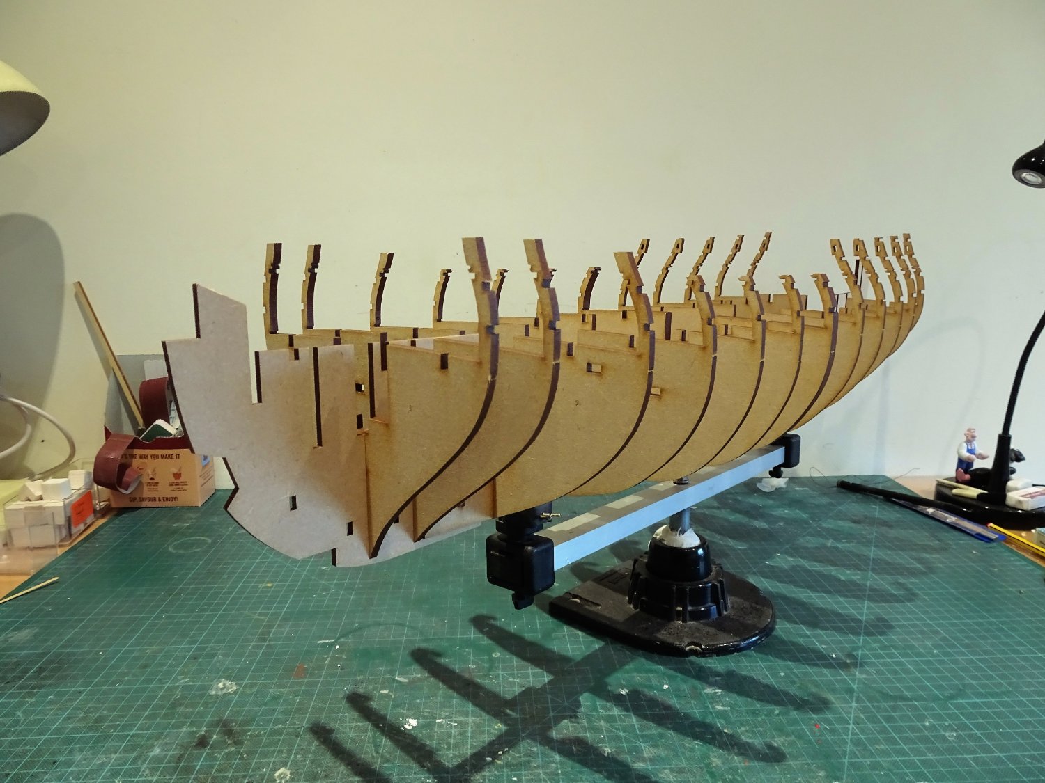
The keel is still quite floppy at this stage due to its length, so I utilised the Amati keel clamp whilst I fettled and inserted the pegs.
0383
With this beast the keel clamp is at the limit of its capacity, and I’m toying with the idea of buying a second to double the length, and provide a more stable support.
A deeper bench would be ideal but not really feasible. I will have to be careful when turning the hull that those delicate frame tops don’t collide with the wall.

0387
Note: There is a minor error in the manual at Stages 21/22. Bulkhead 17 is not removeable as indicated, as it is held by part 40. Chris has issued a pdf amendment addressing this.

0389
A small area of the Orlop deck is represented beneath the Fore hatchways, which I ‘dressed’ using spare engraved maple decking.
0390
The Lower deck slips seamlessly into place and there is a plywood planking engraved section that presumably covers the area that may be observed thro’ the Upper deck openings.
The Orlop and Lower deck decking section are the only parts glued at this stage.
0401
I considered whether to over-plank the Lower deck section, as will be done to the upper deck, but very little will be seen and I think the marked plank lines and butts will be sufficient for the purpose.

0401
Very nicely cut grating sets which I will install ‘as is’ for the lower deck.
0397
The assembly of ladders always give me trouble but a simple jig helps a little.
The final action in this Chapter is to add the Longitudinal bracing pieces (No.30) and parts5b/11b described as a gundeck beam.
0405
Note: Parts 30 are to be found on the 4mm mdf sheet not 3mmm as indicated. May save you a little time in sifting thro’ the sheets.
I did have a slight mishap with one of the part 30 pieces, which broke about one-third along at the weak point of the slot top.
Take care if easing these slots the part is very whippy and care needs to be taken.
0408
This completes this section, more of an assembly than a build at this stage.
I can only marvel at the ingenuity of Chris to design a beast like this held securely together with barely any glue.
B.E.
10/03/2023
-
Thanks Jason.
It's only the equivalent of buying the Pearwood Rigging block kit version, but with Boxwood planking substituted for the blocks, and with additional planking included.
For those who may be interested this is the cutting list for the replacements I envisage.
20pkts Boxwood strip 4x1mm (200 strips.) for decking.
2 pkts Boxwood strip 6x1mm (20 strips) for decking.
4 pkts Boxwood strip 5x1 (40 strips) for gunport stripe and down to waterline
Boxwood sheet 1mm 500mm (L) x 100mm (w) for cutting margin planks, etc;
I bought that carronade from a village shop sometime in the 1970s, it's a heavy cast iron beast, made around the same time. I also purchased a larger scale 24 pounder long gun. Both carriages are made of English oak, and the breeching line I made myself at the Chatham dockyard, sometime in the 1990's
B.E.
-
Always good to finish the deck planking, nice job Kevin.👍
Did you find the strip planking followed the printed layout, or did it start to run off the further you got across the deck?
Did you find the printed pattern a help or hindrance?
Cheers,
B.E.
- mtaylor, Obormotov, hollowneck and 1 other
-
4
-
I don't need luck Kevin - I've got you to follow😜
Cheers,
B.E.
- hollowneck and mtaylor
-
1
-
1


HMS Indefatigable 1794 by Kevin - Vanguard Models - 1:64 - Feb 2023
in - Kit build logs for subjects built from 1751 - 1800
Posted
Fingers crossed for a quick recovery for your boy, the hours surely do drag when they're at the Vets for a procedure.
Some progress that Kevin, I'm still on page one of your log.
B.E.