
.JPG.ca33079f5815b861e67b9c2cccd37982.JPG)

Blue Ensign
-
Posts
4,287 -
Joined
-
Last visited
Content Type
Profiles
Forums
Gallery
Events
Posts posted by Blue Ensign
-
-
Nice work on the pillars Jesse, there is a view of one pair thro' the main ladderway, but the main thing is you know they are there.
The stern frame modification is a bit of a scary one, but they look so much more authentic.
Builders of Chris's new Indefatigable kit will benefit from a stern and Quarter gallery upgrade that reflects the proper arrangement.
B.E.
-
She looks beautiful Chuck, a worthy successor to those 18th c models.
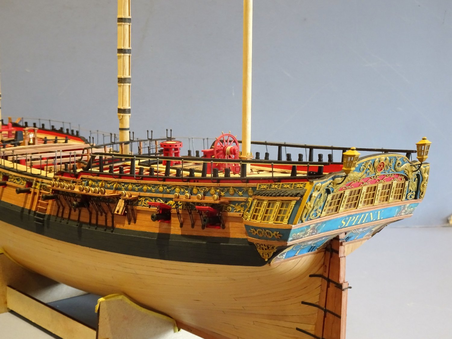
Your build is a fine example to follow and I have used your Winnie build as a guide to my own efforts on Sphinx .
Congratulations on a job very well done, your artistry is much to be admired.
B.E.
- Jack12477, Chuck, Hubac's Historian and 6 others
-
 9
9
-
Hi Ron,
The brass rods have now been removed and I'm going to see how I like her with passing ropes fitted.
I love your macro rigging shots they convey the complex nature of a sailing ship rigging beautifully.
As far as the Fore tack is concerned, a miss is as good as a mile,👍 and it look fine to my eye.
B.E.
- Dave_E, hollowneck and mtaylor
-
3
-
That's exactly how Kit quarter gallery fittings ought to be, would've saved me a load of work on Sphinx.
You lucky investors in Chris's Indy. 👍
B.E.
- Ryland Craze, Rustyj, mtaylor and 4 others
-
7
-
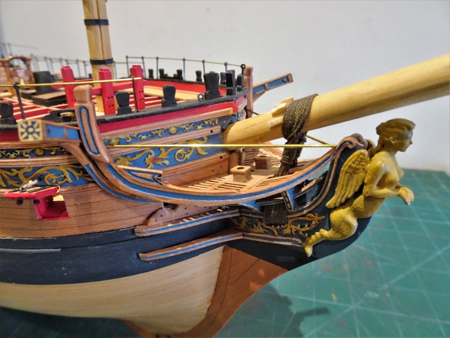
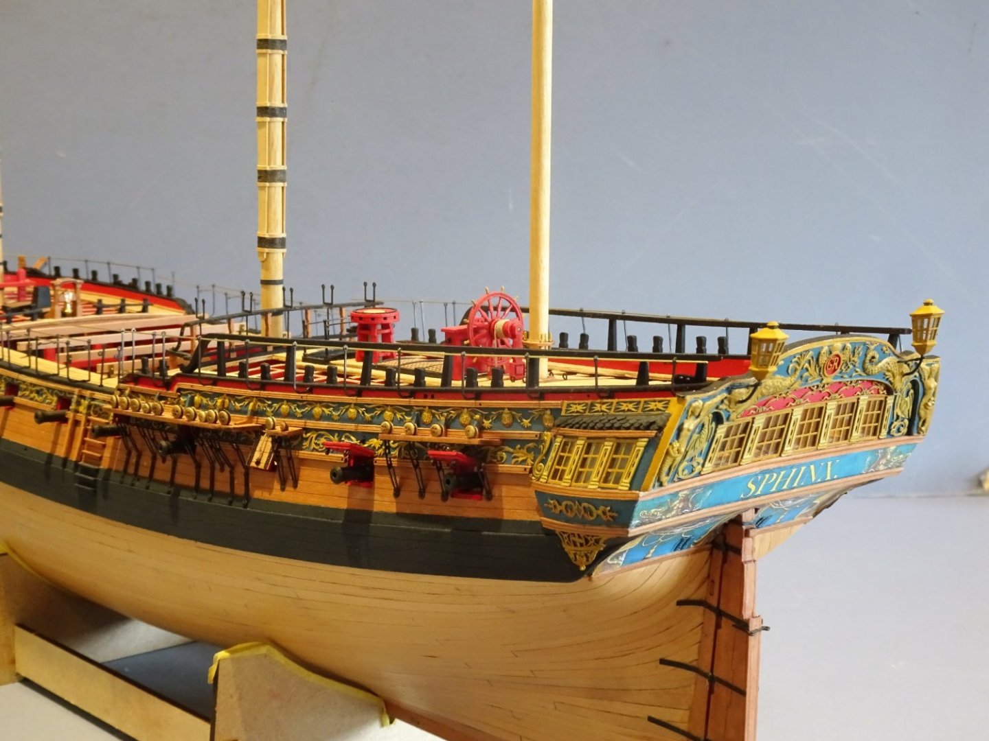
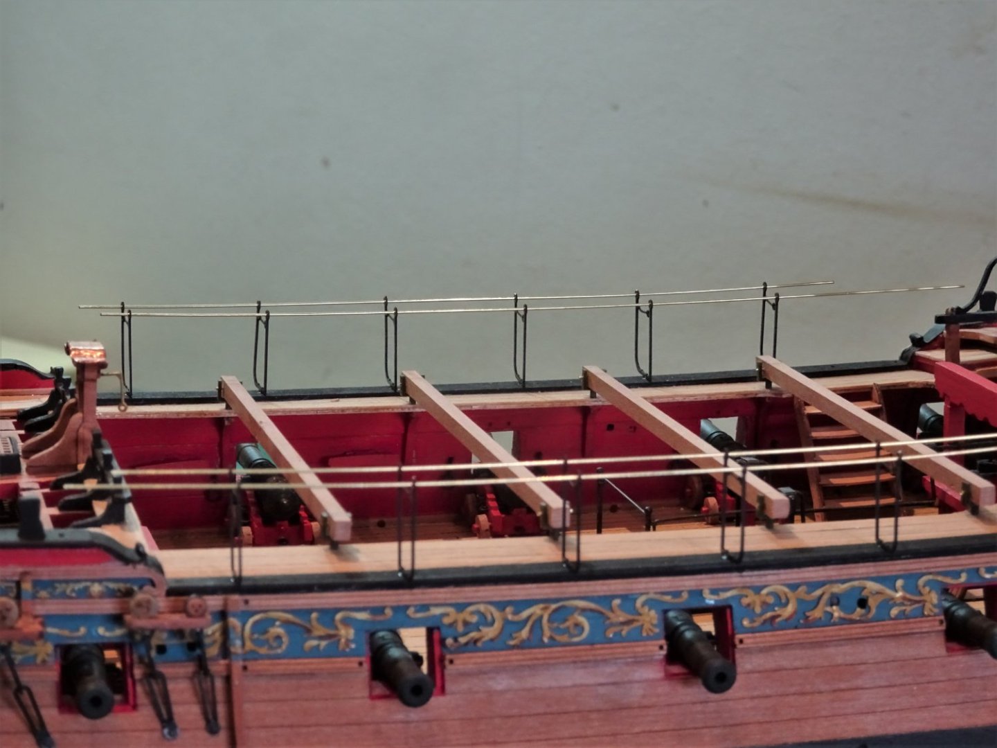
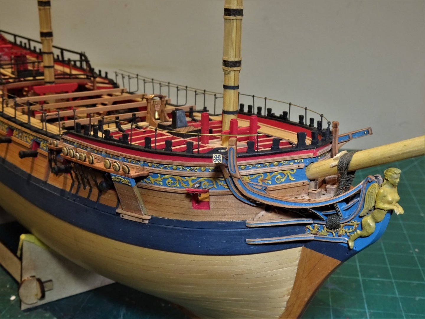
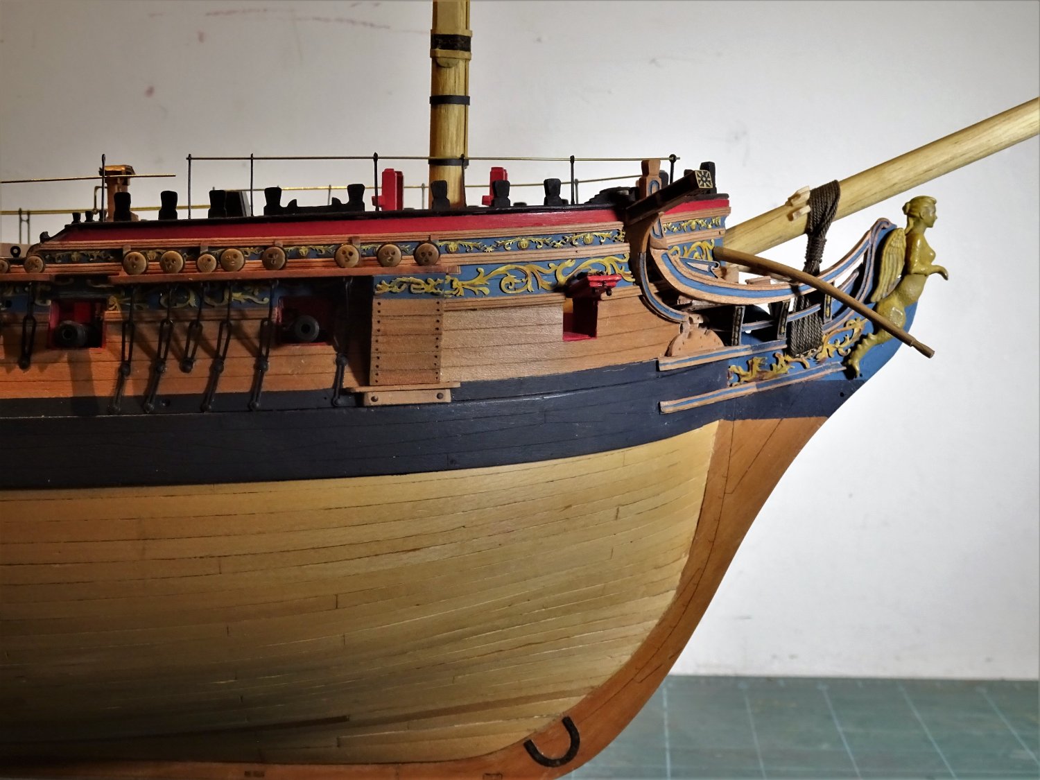
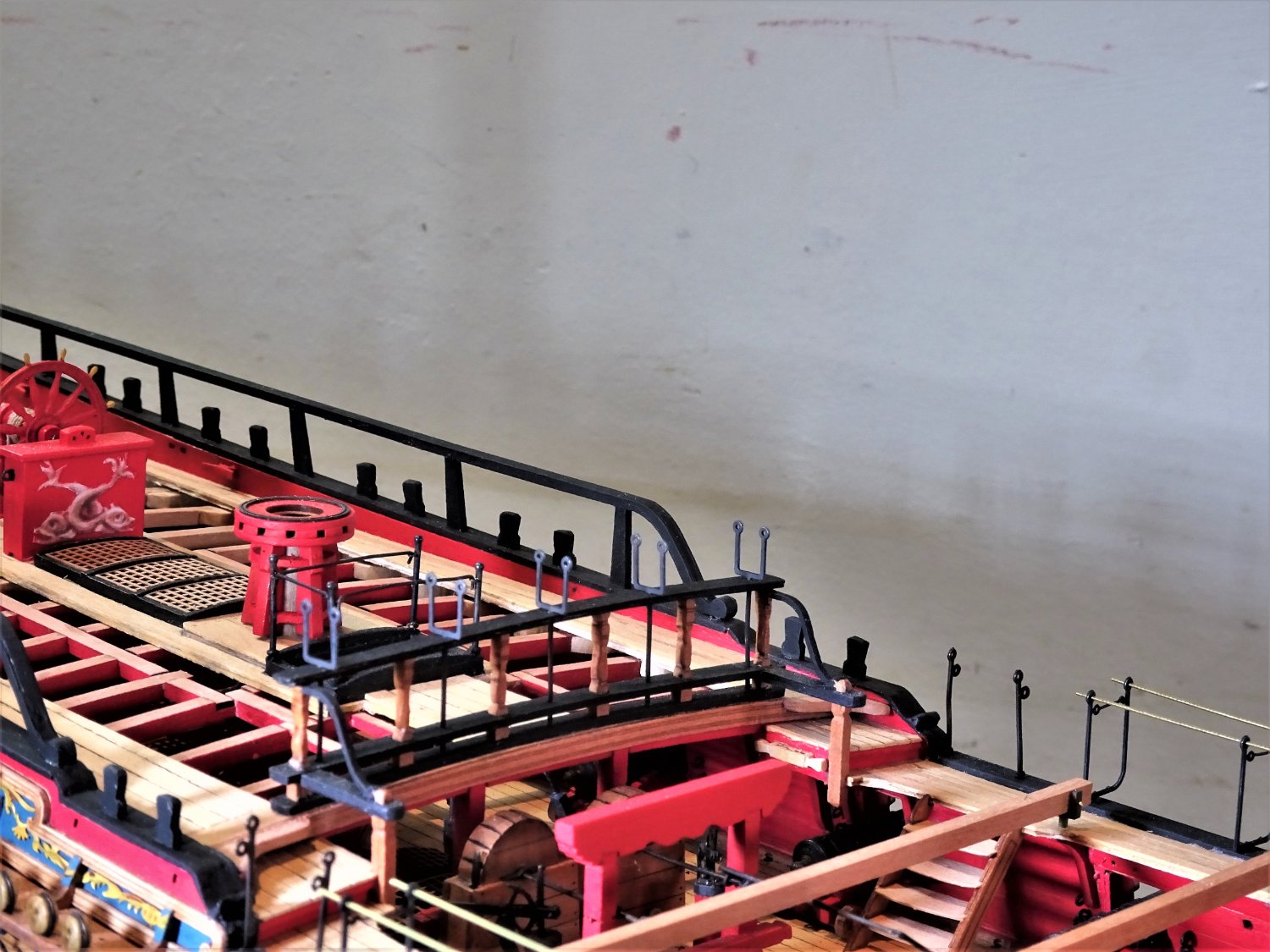
Post One hundred and Sixty-nine.
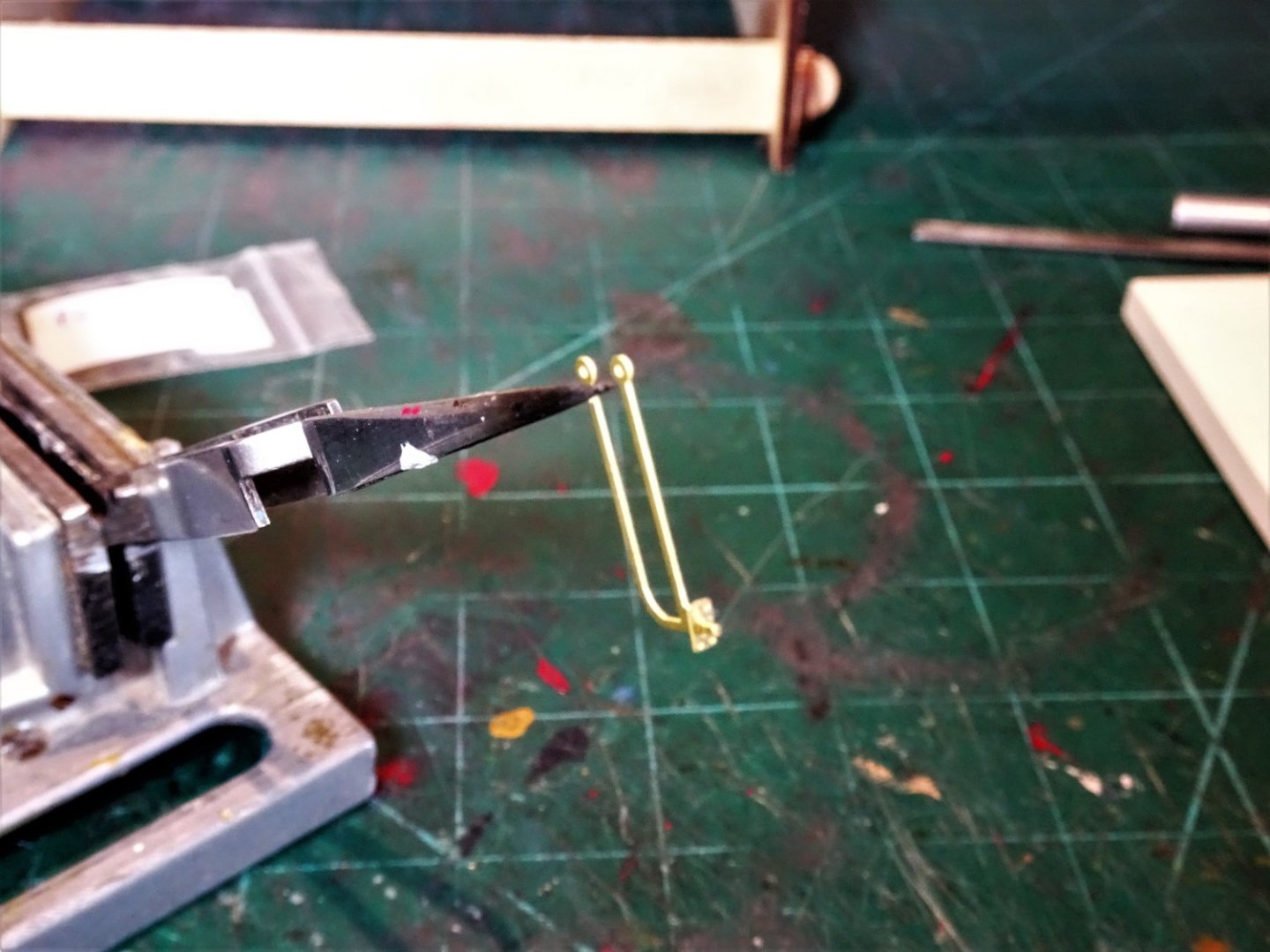
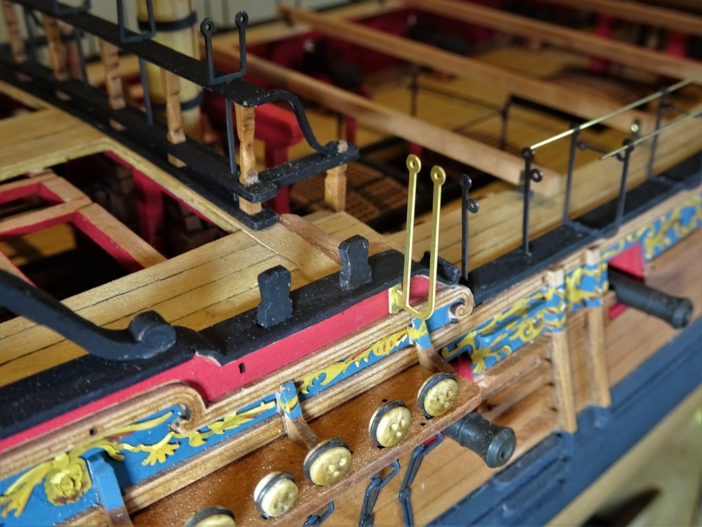
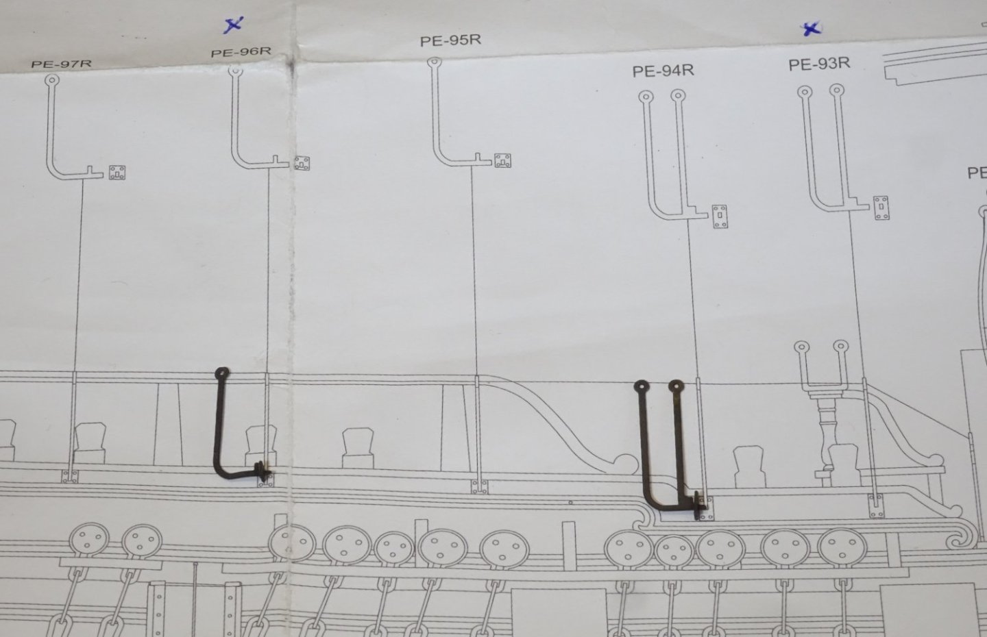
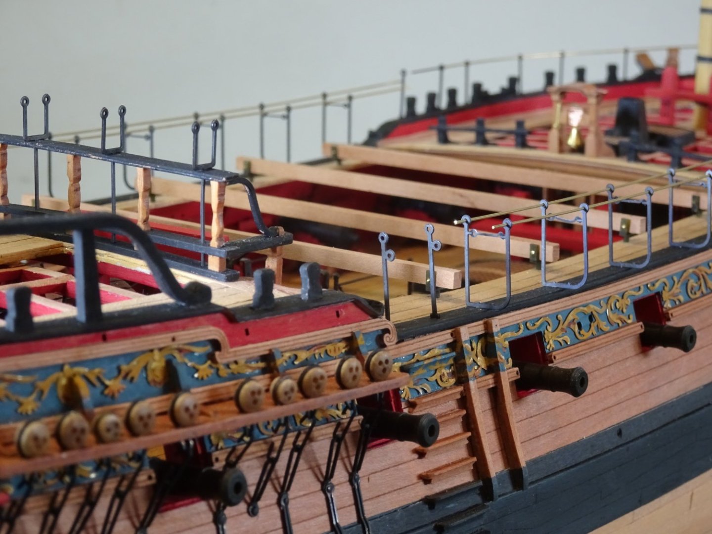
Berthing Rails
One feature missing from the kit are the Berthing rails that span the head to act as a safety rail. It is supported by an iron stanchion positioned midway, and hooks into eyebolts either end of the Main rails.
In a working situation netting would be suspended from the Berthing rail.
It is a little tricky getting the eyebolts set at the right height to suit the stanchion but is a fairly easy modification to make.
I am using 0.7mm ø brass wire for the rails, a couple of modified kit stanchions, and small kit eyebolts.
8672
The first task is to gauge the run of the rail to determine the height of the stanchion and fix the height of the eyebolts.
8680
With the stanchion height determined the eyebolts are fixed and the rail cut to size to fit.

8676
Cleaning the brass is the next task followed by chemical blackening.
8687
8685

8692

8684
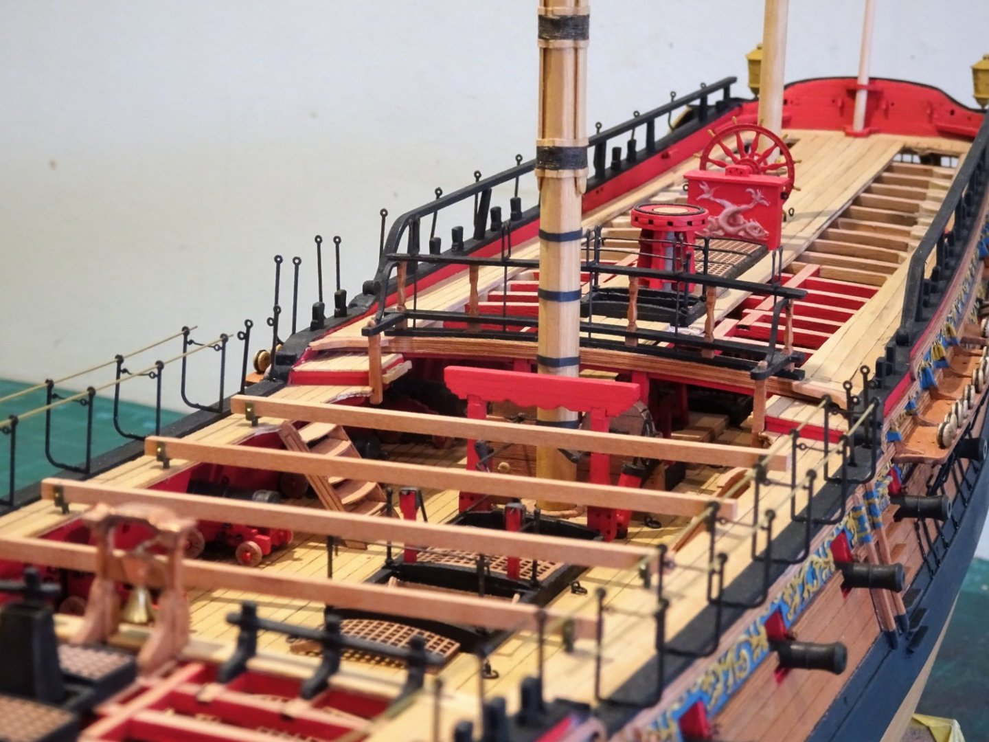
Unlike the Boomkins I quite like the rails in position, perhaps because they are a match for the cranes and other stanchions.
B.E.
06/10/2022
-
That’s about it in a nutshell Marc, succinctly put.👍
B.E.
- hollowneck, mtaylor, Dave_E and 1 other
-
4
-
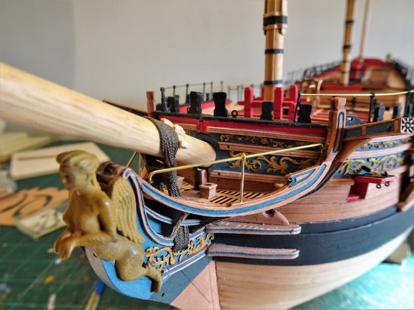
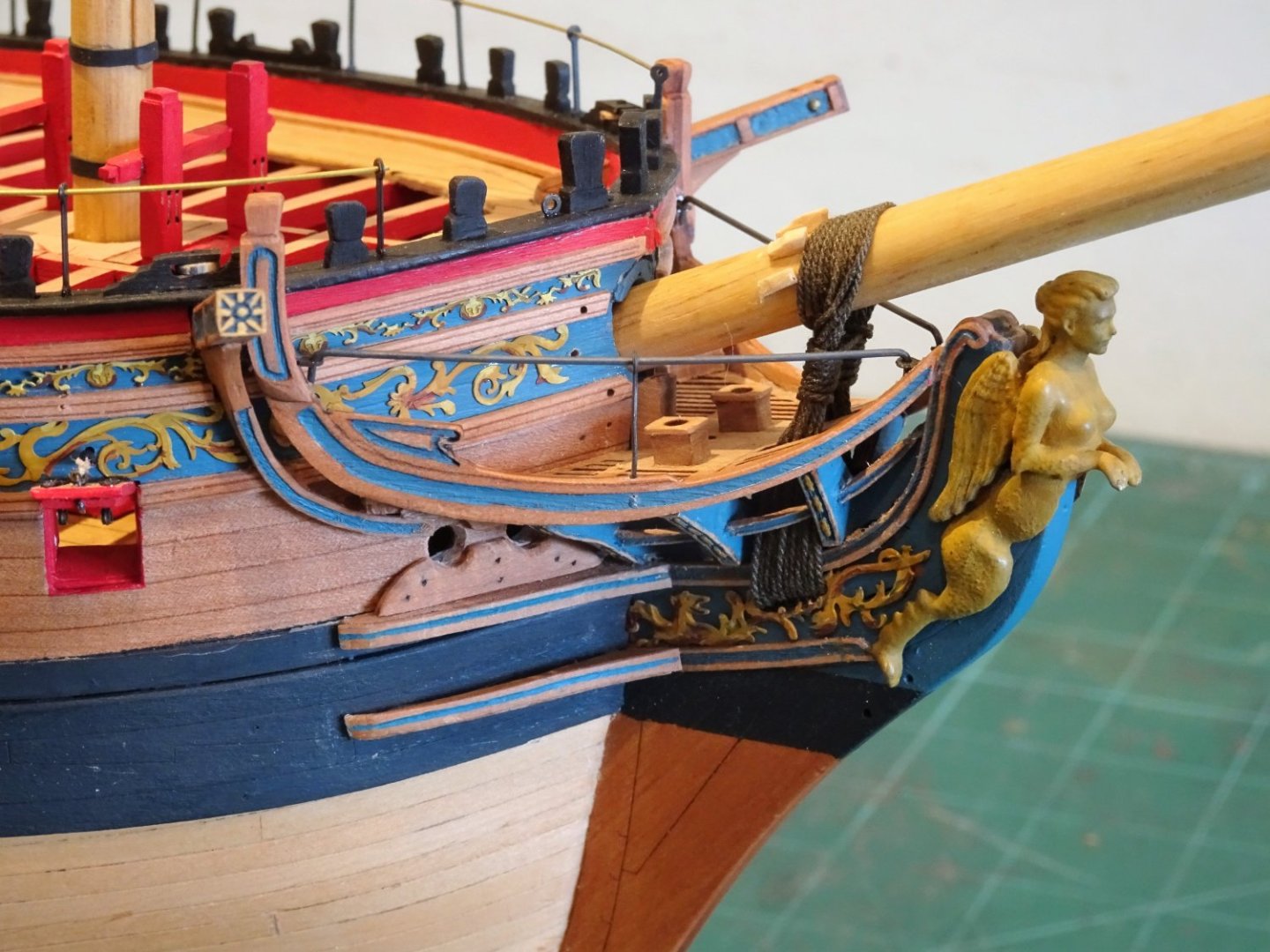
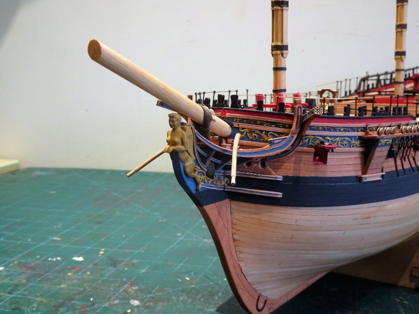
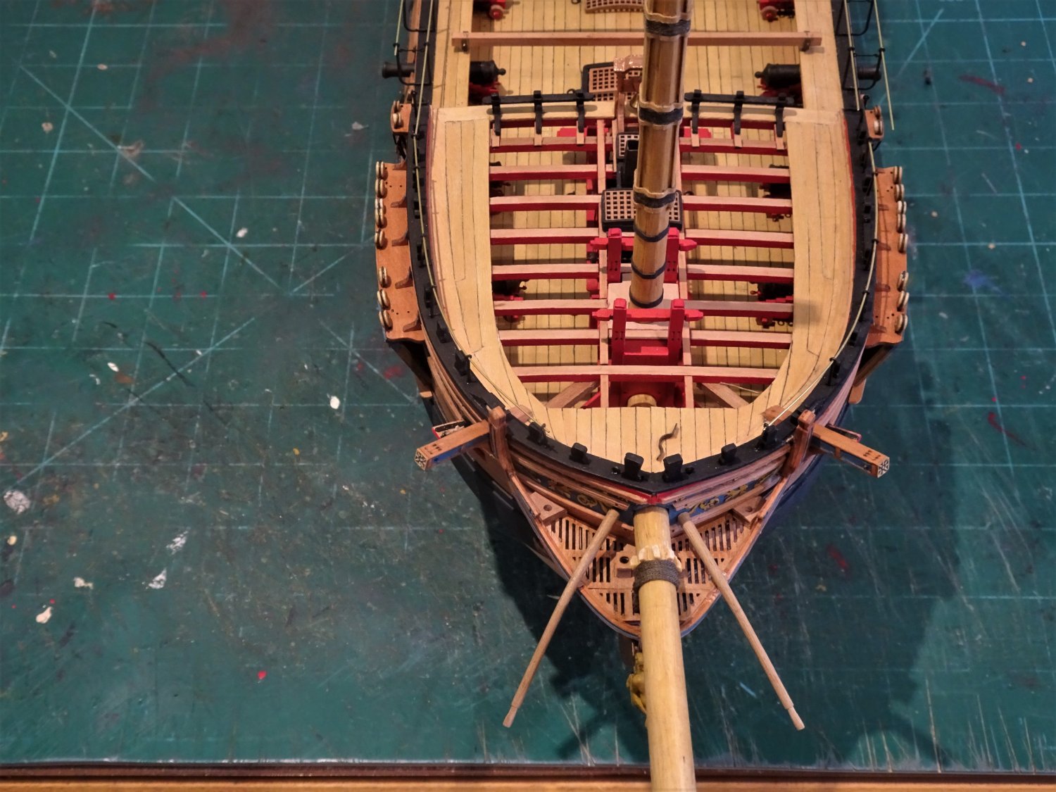
Post One hundred and Sixty-eight.
A question of Boomkins
I have been thinking about the finishing requirements for the headworks.
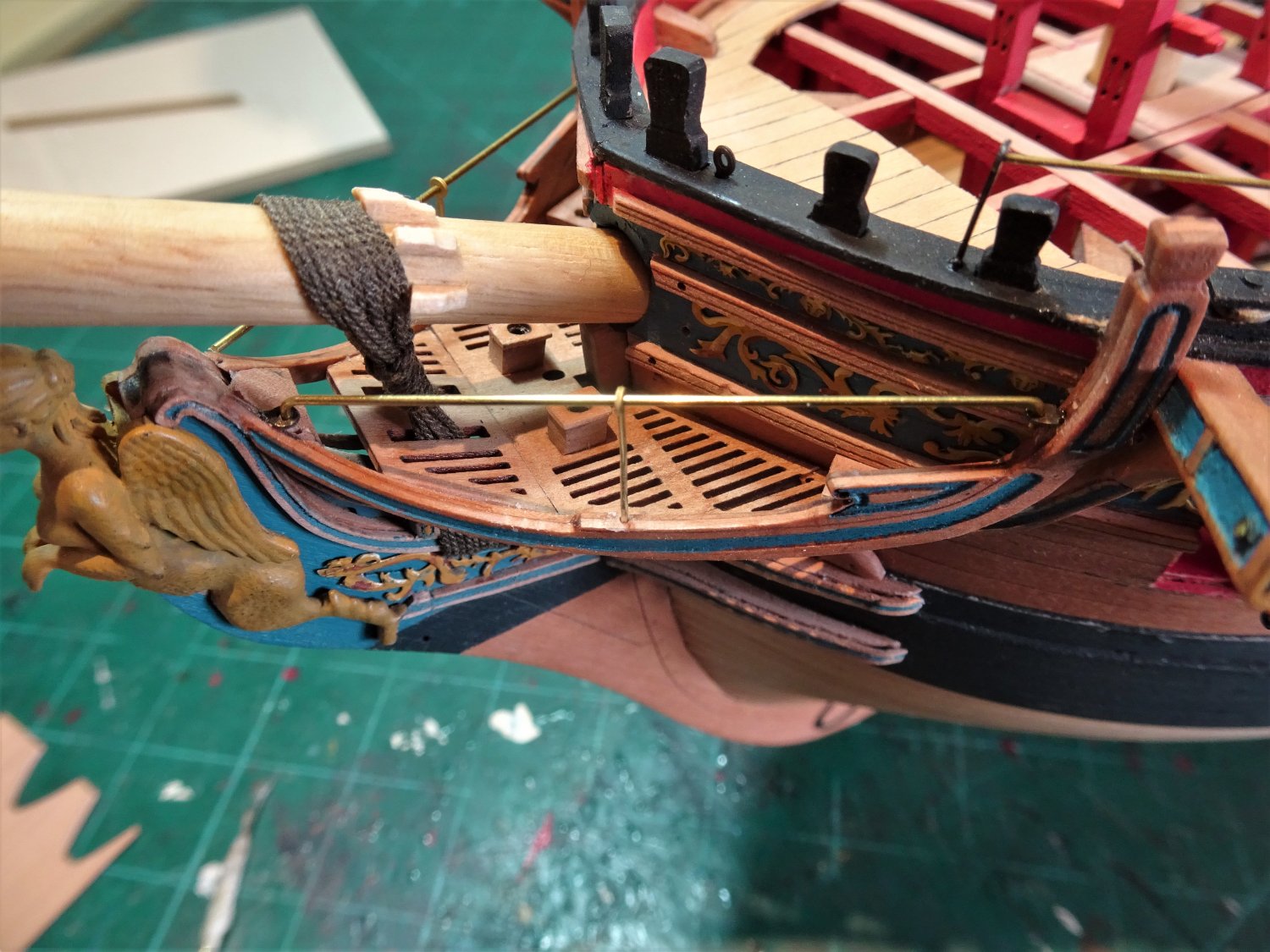
The most obvious items as yet to be fitted are the Boomkins, pointing outwards and downwards to take the Fore tacks.
The contemporary Amazon model has them in place, but most ‘Navy Board’ style models don’t.
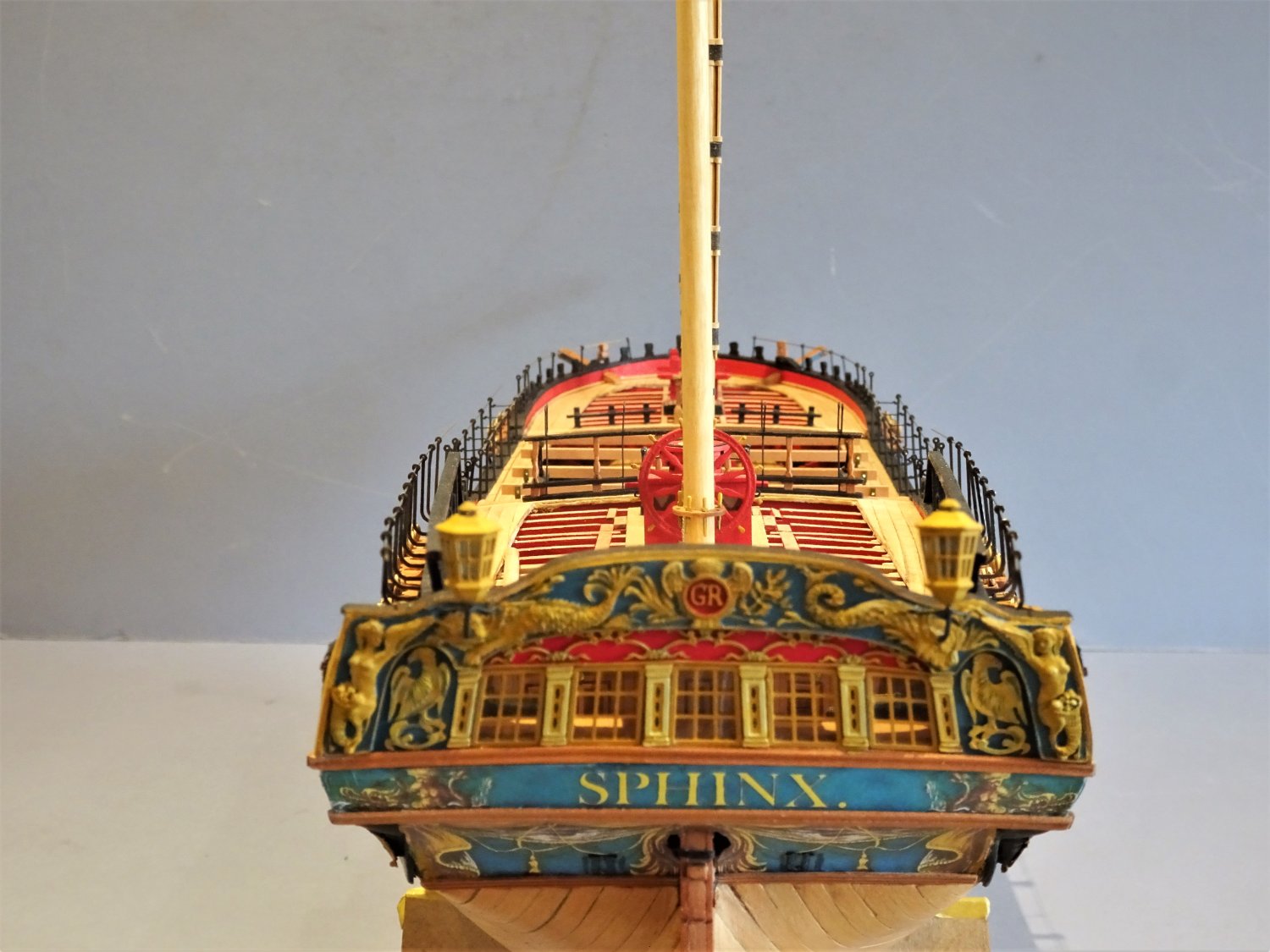
I have concerns that these not particularly attractive spars will detract from the graceful headworks of Sphinx.
The only way to find out is to make up the Boomkins.
.thumb.JPG.68c8331ded615821458c67d7da8c5665.JPG)
8669(2)
The Boomkins as presented in the kit are straight, but I decided to add a degree of downward curve beyond the headrails.
This was applicable up to around 1780, but my main purpose is purely one of aesthetics, adding a little more grace to these utilitarian spars.
The kit version has a scale length of 9’ 7” (46mm) giving an outboard length of around 5’ 6”
It looked a little short to my eye.

8646
The Pandora book plans indicate an overall length of 13’ (61.9mm) with an outboard length of 8’ 9”
Pegasus has Boomkins with an overall length of 11’4”
Lees refers to the earliest booms protruding outboard by around six feet but longer by around 1733.
The acid test is really whether the Fore tack has fair running once all the other lines running inboard are in place.
This won’t be of relevance on this build, but the subject tasked my mind a fair bit during my Pegasus build.
I finally settled on a Boomkin length of 54mm which looked best to my eye.
The Boomkins are made using 3mm ø walnut dowel, I selected a colour on the paler spectrum of walnut.
The boom tapers to 2mm at the shoulder that retains the strop of the shoulder block that serves the Fore Tack.
The shoulder is 3mm long.

8658
The angle of the Boomkins is positioned to line up with that of the Foreyard when braced sharply. (Lees)
8664
8656
8648
8655
To my eye they do detract from the grace of the headworks so skilfully replicated by Chris Watton, and I won’t include them on my display.
On a masted and rigged version, they would of course be a necessary requirement.
I will next see if the Berthing rails make the cut.
B.E.
05/10/2022
- jpalmer1970, gjdale, Rustyj and 20 others
-
23
-
Quite a journey you've had with this kit Glenn, and she does look impressive.
Well done.
B.E.
- Ryland Craze and mtaylor
-
2
-
The relationship between the bridle port and the others Is fixed as they are pre-cut on the pattern. The rail runs between the ports, above midway height, does your tape need a little tweaking?
There seems to be two options:
Run the rail smoothly along the hull letting it cross the Bridle port where it does.
Remove the planking in the area of the Bridle port, and infill to adjust the shape before re-planking. In this case the width of the Bridle port could be made slightly narrower, as was the actual case.
I think it more important that the rail looks to have a smooth sweep along the hull.
B.E.
-
Thank you Sir, for your kind words, but if anything has been nicked from the Science Museum, it’s nowt to do wi me governor😉
B.E.
- Dave_E, mtaylor, hollowneck and 1 other
-
4
-
-
-
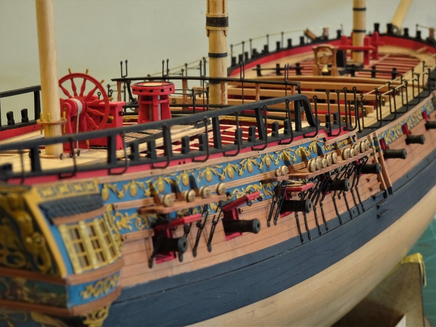
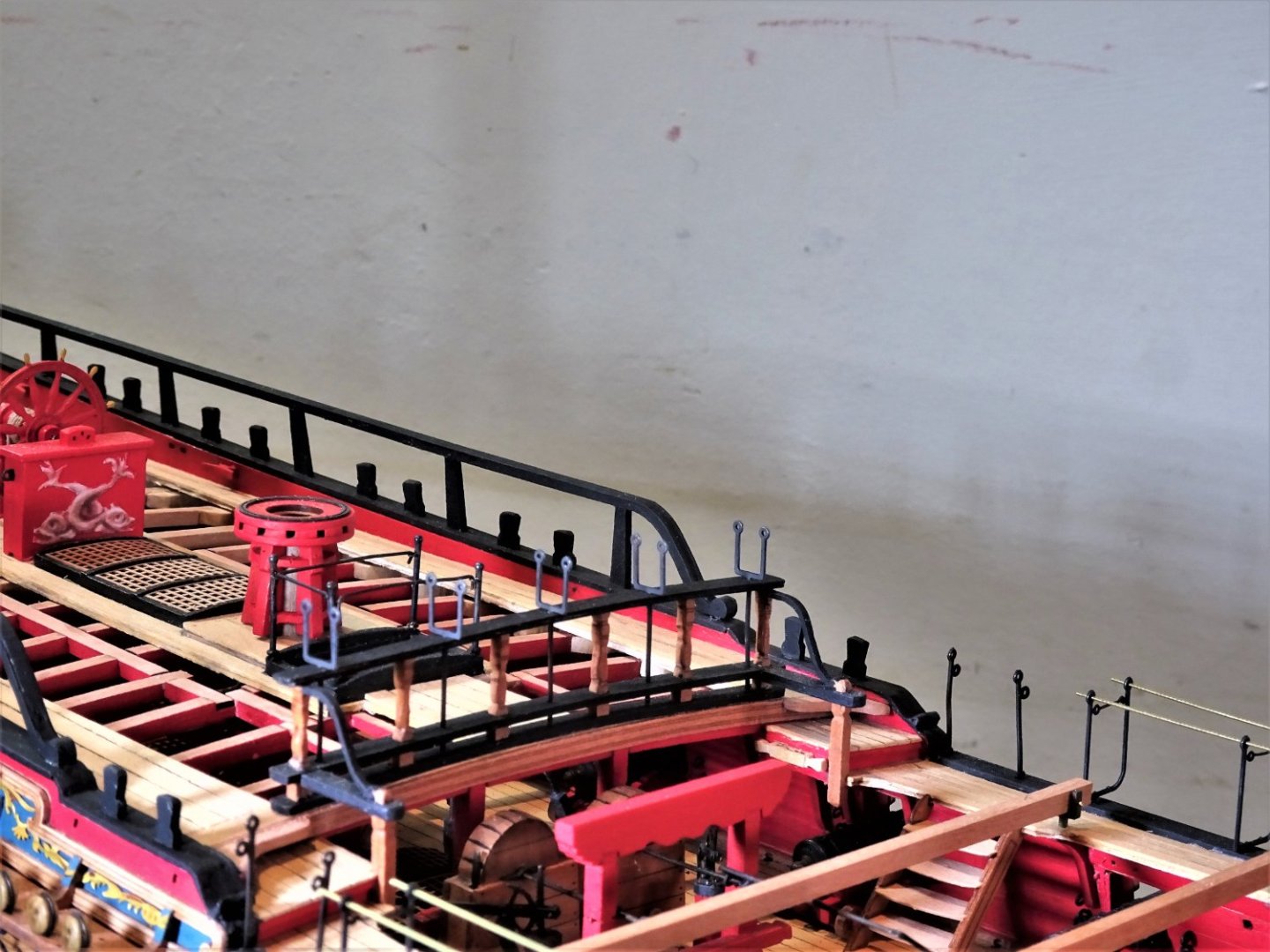
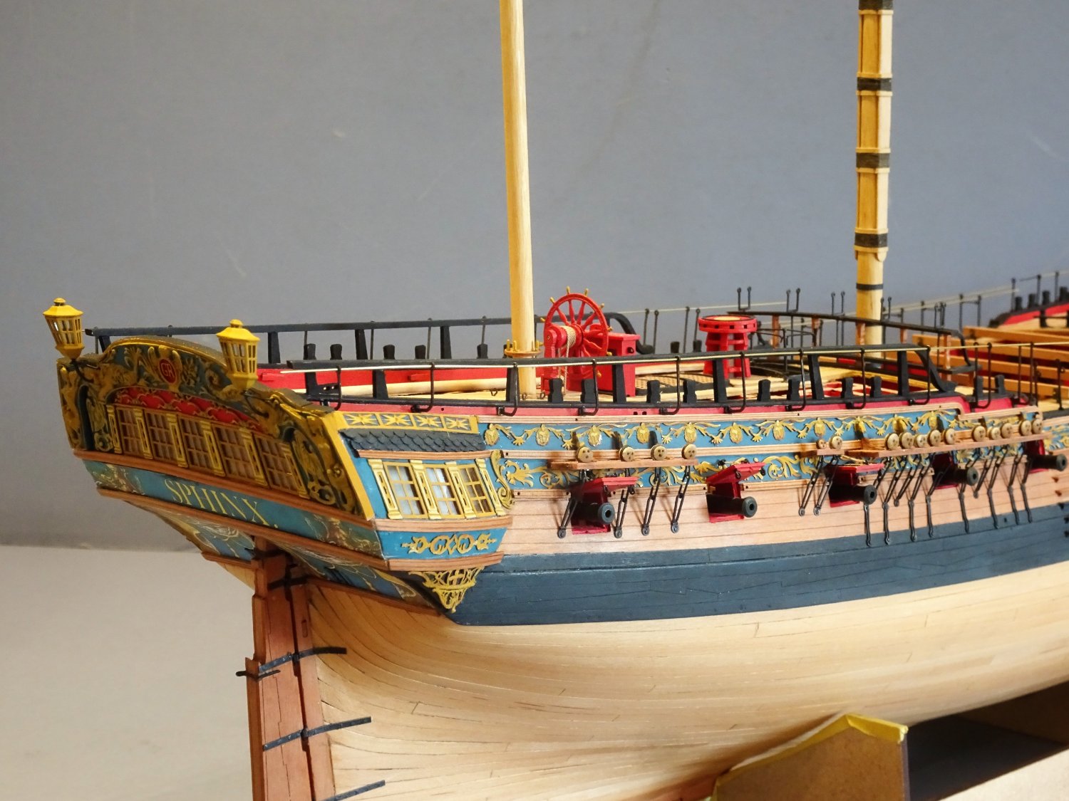
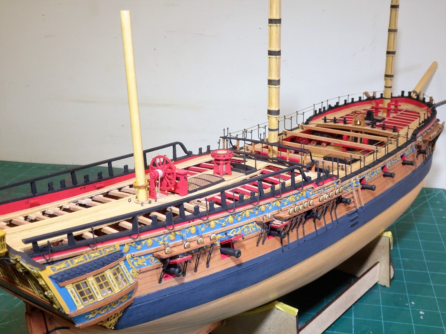
Post One hundred and Sixty-seven.
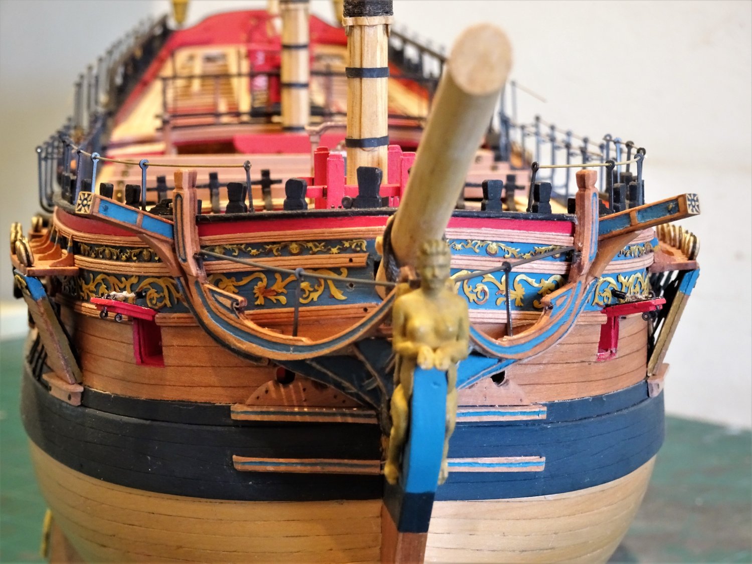
More on Cranes
Having pondered on the subject of the Quarter cranes for a few days, I have finally decided to fit them.

8630
I do like to see iron work on ship models, and they do not obscure or detract from the decorative topsides which was my main concern.

8635
8629
I have included the micro back plates, but they are the very devil’s invention for handling and filing to fit.

8620
Several of them pinged away into the ether never to be seen again, but faux plates are easily replicated using thin black card, and the difference cannot be detected.

8615
As with the other cranes thin brass wire is threaded thro’ the eyes to help maintain position.
8621
Even with short nubs the cranes held well using a smear of ca to attach to the hull.
.thumb.JPG.f8202cad37677f876a0e225d69e0de1a.JPG)
8614(2)

8628
Looks a little like a forest of cranes in these macro shots, but foreshortening gives something of a false impression.
.thumb.JPG.8864cf5b05732eb64a692e13c80bac99.JPG)
8612(2)
8631
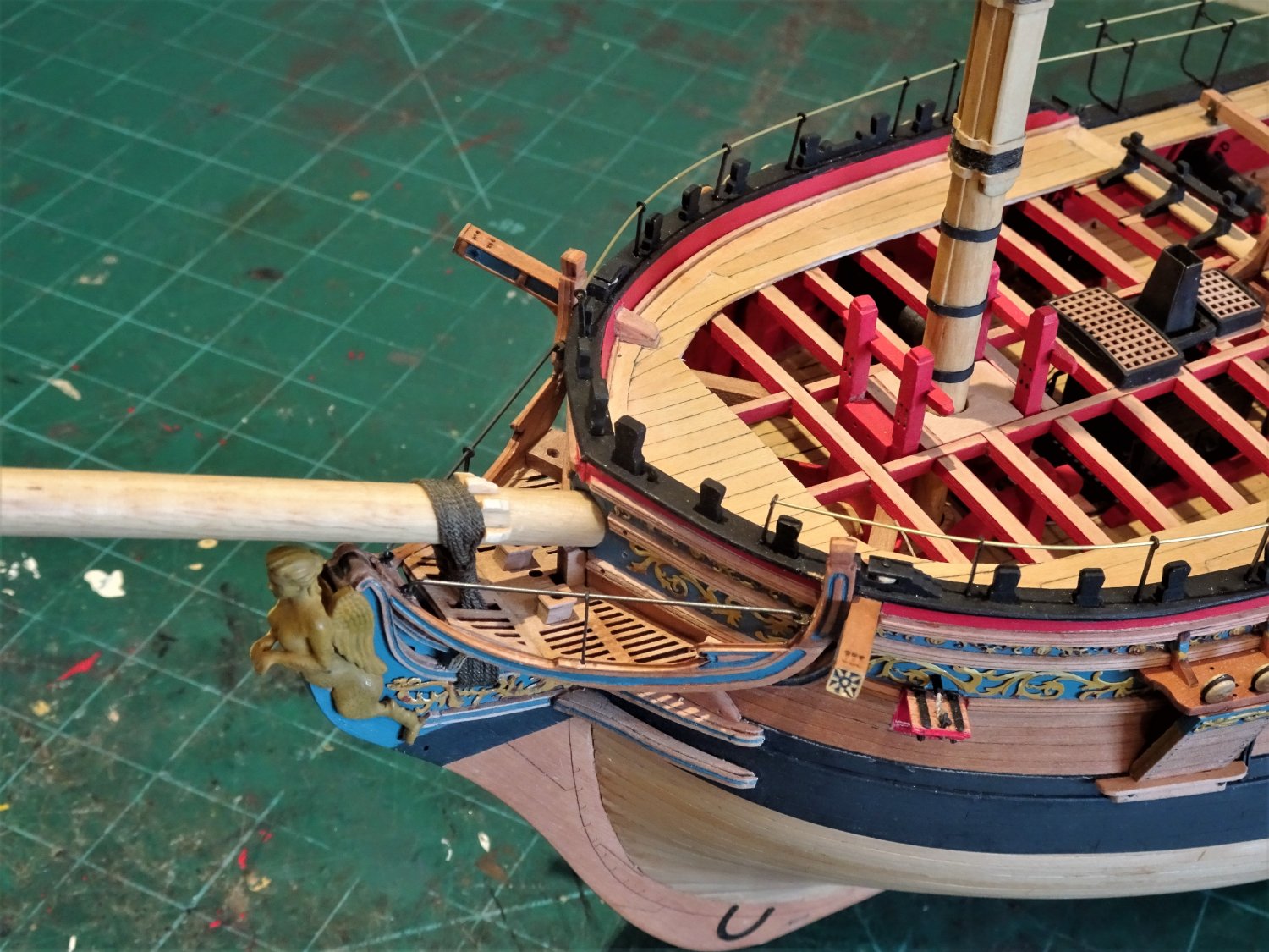
A little more enhancement to the Headworks now.
B.E.
02/10/2022
-
Nice work on the internals Yves, pity to have to cover them, but there’s satisfaction knowing they are there, and of course you have the photos.
The below decks shots are a great record to have.
B.E.
- Kevin, mort stoll, mtaylor and 1 other
-
4
-
Thank you, Glenn, Dave, and Ron.
@Ron.
I can see your dilemma, there is only effective room for the bowers just aft of the forward port with the bill supported on the fish davit support.
If the spare Bower and sheet anchors are fitted, the bill will have to be supported on the forward end of the gangboards.
When I look at rigged contemporary models where anchors are fitted, there are mostly only two in the examples I have seen across all rates. Most rates would have carried at least three large anchors, plus Stream and kedging anchors.
In terms of your under sail, ‘at sea’ depiction at least the anchor cables would have been removed and the hawse holes plugged.
The anchors would be secured with ring stoppers. Shank painters and lashings.
5464

5466
This is how I envisage the Sphinx anchors being stowed, which fortunately I won’t be troubled with. In practise there would probably be a chock of sorts where the anchor palms of the sheet anchor would rest.
5467
Pegasus carried slightly smaller 20cwt bowers, the aft anchor here is the smaller Stream anchor.
You can see here the shank painters, ring stoppers and lashings.
I hope this helps a little, but the best information about handling anchors is contained in the book Seamanship in the age of sail by John Harland.
Regards,
B.E.
- fake johnbull, davyboy, DelF and 4 others
-
7
-
-
Thanks Ron, I can understand you omitting the flanges, they mostly need filing down to fit and they are the devil to hold to do it. On a fully rigged model their absence won't be missed.
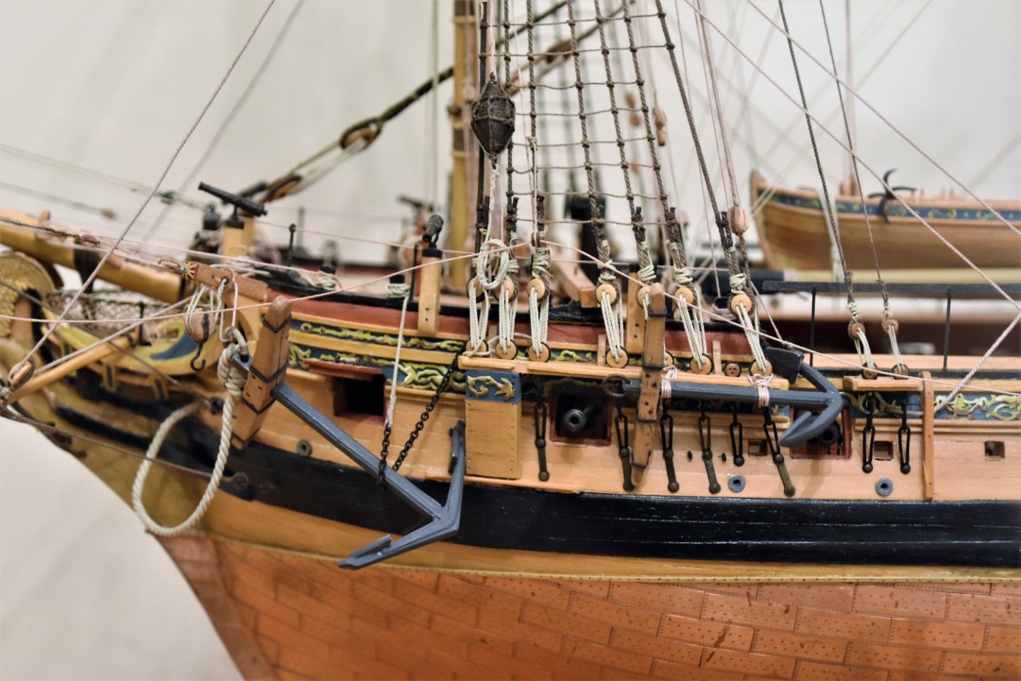
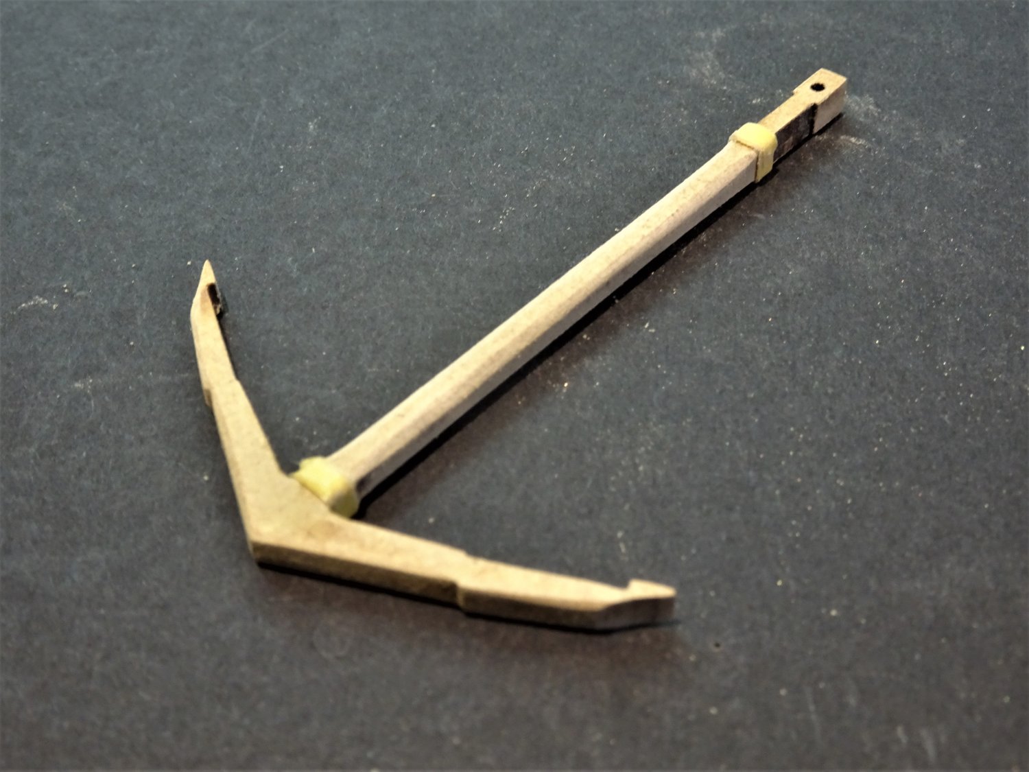
Post One hundred and sixty-six.
Looking at Anchors.
As a break from the main event (and to avoid making a decision on the cranes) I decided to make up a couple of the Bower anchors.
.thumb.JPG.3bebcd38e689b3d5f8cafb379b61e021.JPG)
8590(2)
These are pre- formed in mdf, a departure from the usual white metal versions.
I am familiar with ‘wooden’ anchors from my Cheerful build and excellent realism can be achieved.
.thumb.JPG.201d9db8bc37f5811ee8e1a822c5425b.JPG)
8591(2)
The Sphinx anchors, effectively blanks, will stand a fair bit of fettlin’ to make them look the part, assembled as is and they will look clunky and unconvincing.
Builders could do worse than consult Chapter 14 of the download instructions for Cheerful, from the Syren Ship model Co.
One major difference tho’ is that the Syren anchors were made of Boxwood which will take a cleaner edge than mdf.
This is relevant because there is properly a narrow bevel edge running down the shank and along the arms.
If this can’t be done cleanly on mdf, it is best left alone.
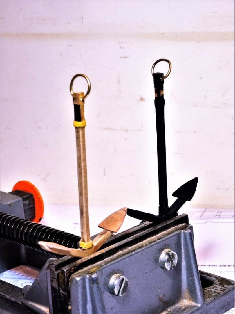
As I’ve got four to play with, I think I can risk one to check it out.

8576
The anchors clean up very well and the sanding of the bevels didn’t result in a feared fluffy edge. At least with mdf, sanding is a fairly easy operation.
For the life of me I haven’t managed to find the kit anchor flukes (0.8mm ply, part 52) or even find them on the plan sheets.
Fortunately, they are fairly easy to replicate, there is a 1:64 plan in the AotS Pandora book.
.thumb.JPG.9ebe8e7daaaedab065491d6fb97e30f6.JPG)
8578(2)
I made them from 0.8mm Pearwood stuff.
The bill beyond the palm of the anchor should ideally be fined down to more of a point than the chisel finish shown on the kit anchor, which looks a little broad to my eye.
The anchor stocks are Pearwood, faced with engraved Pearwood patterns detailing the treenails and iron band positions.
.thumb.JPG.596e09ed4345908eef8bfa576bae2ae8.JPG)
8580(2)
In this photo the anchor stock is shown as supplied, but each half should properly have a slight taper on the outer faces from the centre section banding to the tips which needs to be done before the detail patterns are applied.
Anchor ring
For a 29cwt anchor Steel gives the thickness of the anchor ring as 215∕16”, 18⅛” in the clear.
.thumb.JPG.2c6f01764beb3b45a8c8af9abad820ce.JPG)
8583(2)
This scales to 1.00mm ø brass wire formed around (in my case) a 7mm ø brass tubing section.
8588
The rings are fitted before the stocks.
.thumb.JPG.b874e50704918aa6a6a67d65de512fa9.JPG)
8592(2)
The stocks are fettled to sit square at right angles to the arms, but when glued to the shank the glue is applied to only the outer third of the stock to allow the split line to be apparent.
.thumb.JPG.d45c8bbfd2e5f5c9614e0e36ff36b6e8.JPG)
8600(2)
The stock bands are slices of heat shrink tubing which is my preferred medium for this sort of thing.
.thumb.JPG.6d1dc810a6a9a538fd50200f477c78e3.JPG)
8606(2)
For the ring puddening I have used Syren 0.30mm ø line.
.thumb.JPG.d794eae7132a3af19214fd89fbd15e50.JPG)
8608(2)
.thumb.JPG.c5969436f32c5c1c3fe27aa6e0a623df.JPG)
8609(2)
.thumb.JPG.8610f5a20518d7eb5a81125a8c493ced.JPG)
8601(2)
The final stage is to apply a little weathering powder to enhance the iron look.
The anchors won’t be fitted on the ship but will be included in the display case.
B.E.
30/09/2022
-
They look excellent figures Ron and have come along at just the right time to man your Camilla.
I'm not sure the athletic member of the gun crew with the admirable 'six pack', whose job it is to insert the charge down the barrel, would be pleased about being called a powder monkey.
Perhaps Chris will produce a young boy, short and nimble, to transfer the charge from magazine to station. 😉
B.E.
- hollowneck, druxey and mtaylor
-
3
-
I'm sure you will enjoy this build Erdict, it is a fine model to make.
As for emulating the builds of others, we all do it, picking up ideas, and learning from methods employed, it's a lot of what MSW is all about.
Have fun.
B.E.
- hollowneck, Ryland Craze, mtaylor and 4 others
-
7
-
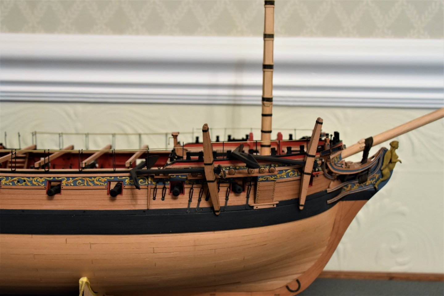
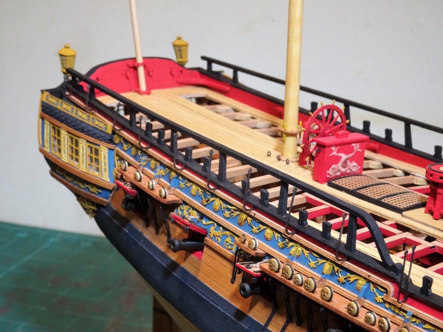
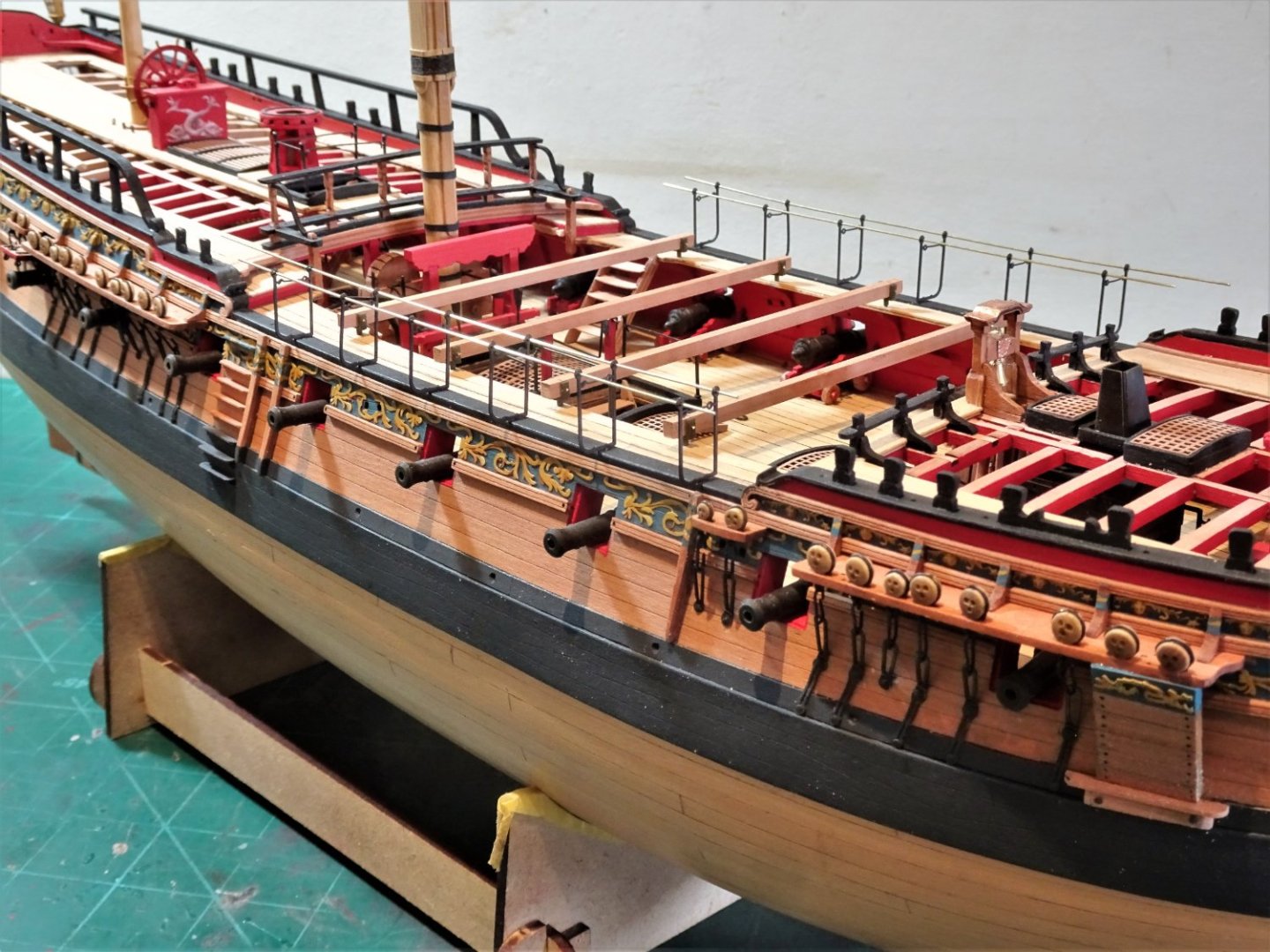
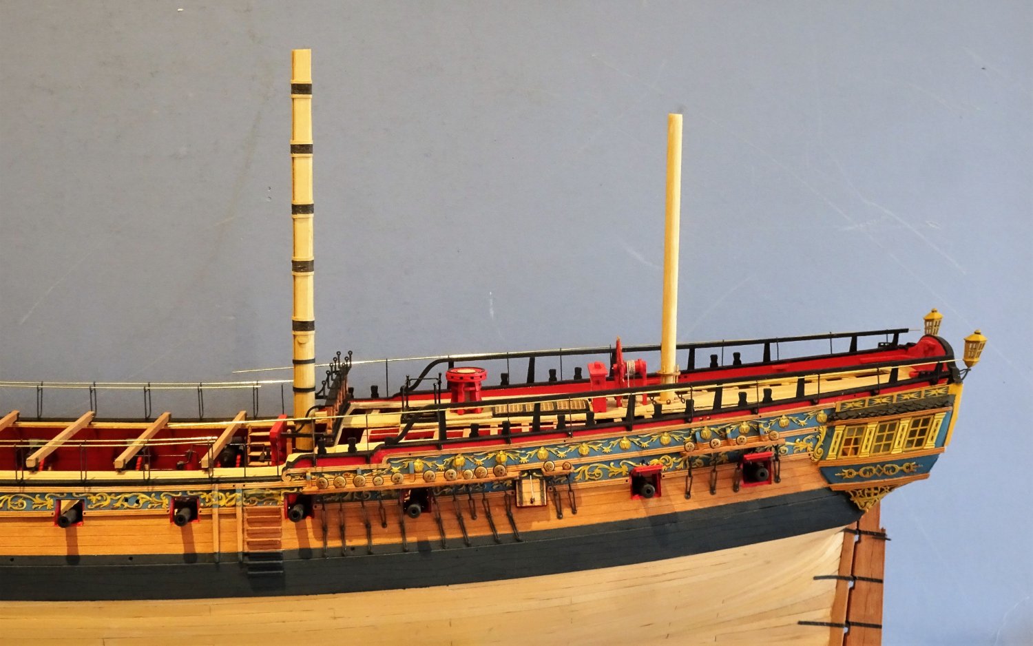
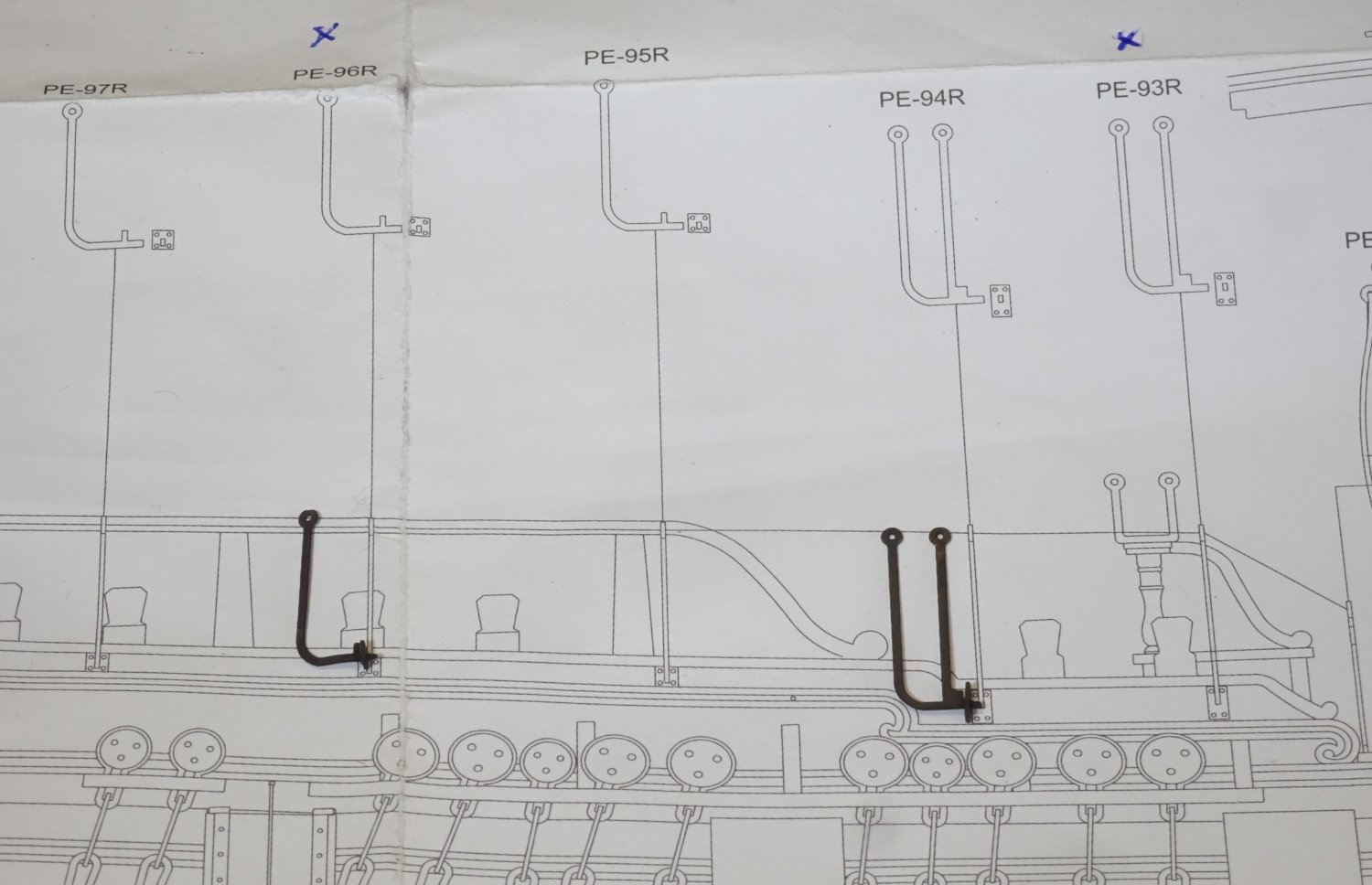
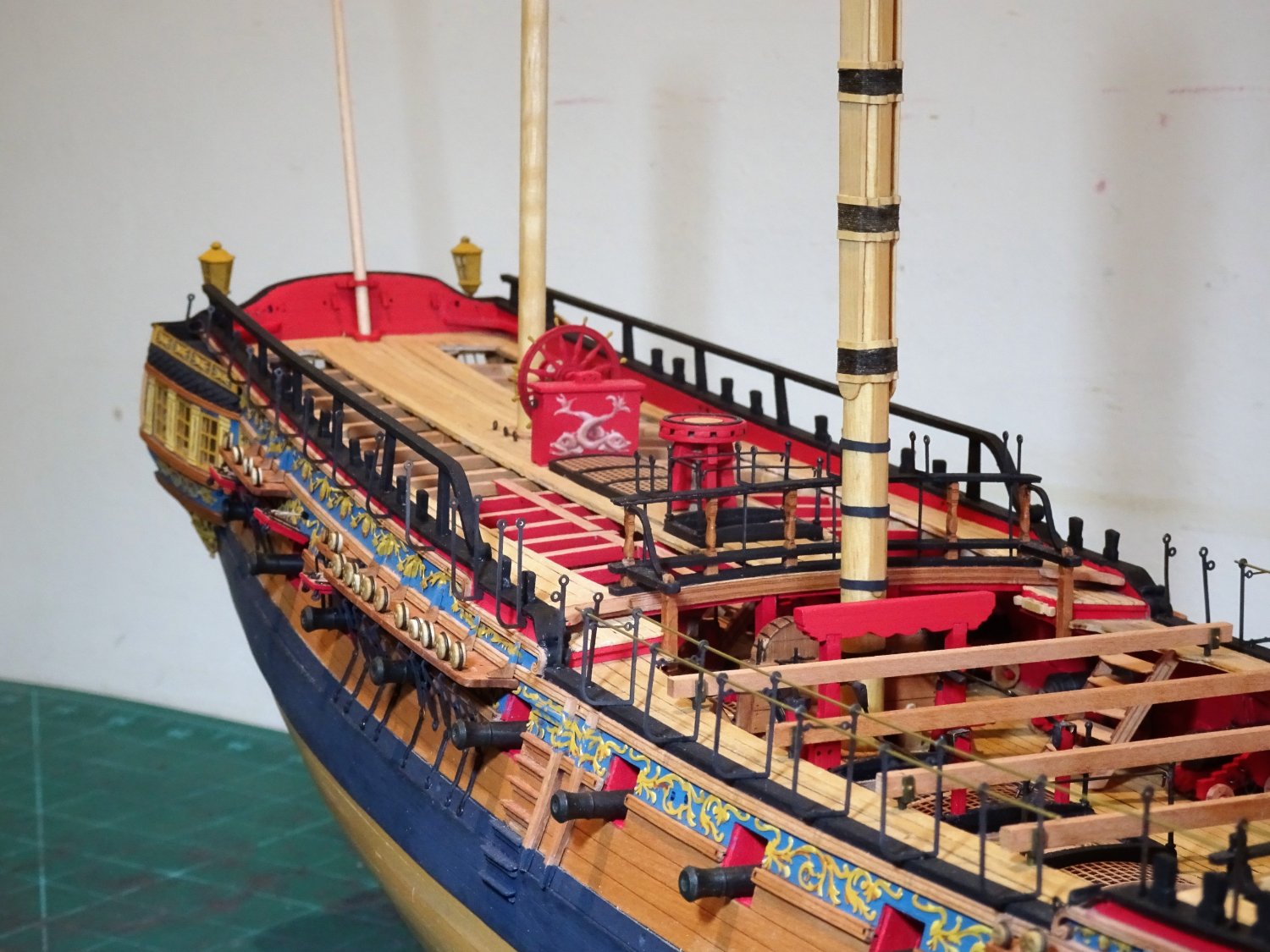
Post One hundred and Sixty-five.
Back to the Qtr deck cranes
I’m not entirely convinced about fitting these items, but I’ll look at them as the manual and instructions are somewhat thin on these fittings, and hopefully fill in some of the gaps.
As previously noted, these are position specific so will be dealt with on a pair-by-pair basis. There are eleven sets of these which require sorting, fettlin’ and blackening before fitting.
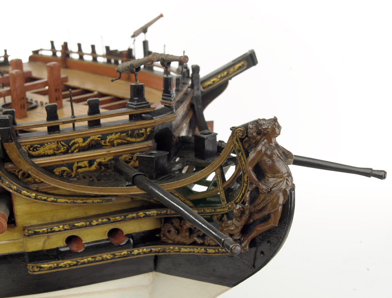
They are present as indicated on the contemporary model of Amazon.

Amazon Model
The cranes look a lot finer on this contemporary model than on the kit.
I also note that the first two cranes are single unlike the kit, but to what purpose?
8530
This is the foremost crane along the Quarterdeck and the base plate has been fitted to the crane prior to fitting to the hull.
The plate mortise required some adjusting before it would fit onto the crane, and the plates needed a little filing before they would fit into the available space.
8528
The crane in place; they are fiddly little items to assemble, but it is a mark of Chris’s attention to detail that the base plates are even supplied, I suspect many kits would have the cranes just slotted directly into the hull, even if they were supplied in the first place.
.thumb.JPG.411b41e4293a5bef329dbfad02a3b92f.JPG)
8551(2)
I do not intend to glue the base plate to the crane, only the stem of the crane to the slot in the hull.
8573
The cranes are chemically blackened with the base plate attached and a spot of ca will secure the unit to the hull.

8560
Those two foremost double cranes do rather catch my eye, even if they are a logical structure. For this section, beyond the Quarter rail, there is nothing otherwise to secure the inboard side of any netting.
8559
8562
8556
For the purpose of this test I have left the base plates off to give a more secure fit in the hull.
8568
I don’t think I would like to fit these cranes post full rigging, it will be a very tricky operation, and I can understand why James left them off.
Personally, I would have fitted them first, but if fitting post rigging, I would have left the base plates off, which will make it easier to get a firm fit into the hull.

8565
Another decision to make but one I will defer for a few days while I get on with something else.
B.E.
26/09/2022
-
-
I run out of superlatives to describe the quality of your work Glenn, suffice to say I greatly admire what you are achieving.
Regards,
B.E
- FrankWouts, glbarlow, hollowneck and 1 other
-
4
-
I'm sort of thinking that also Glenn, after all Navy board style by its nature is incomplete in many respects, and I don't want to over egg it.
I usually ask myself - What would Chuck do but he hasn't got to the iron work aspect of his Winnie yet, and maybe doesn't intend to.
The waist cranes are fixed, along with the Foc'sle stanchions, but the breast rail cranes are removeable.
The contemporary Amazon model has them fitted, but they somehow look finer on that model, and not so intrusive
I think I will make up a few of the quarterdeck cranes to get an impression of how they will suit my eye and refer back to my peer group.
Thanks for your advice.
Regards,
B.E.
- jpalmer1970, davyboy, Gahm and 9 others
-
12
-
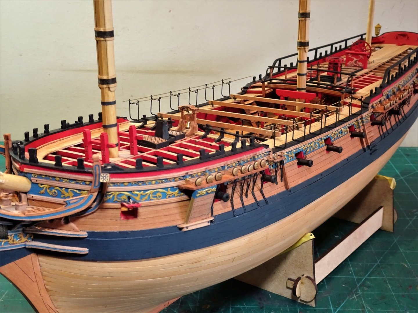
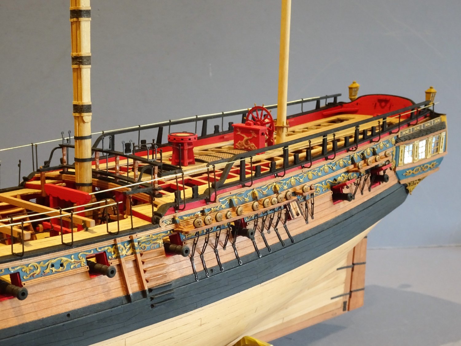
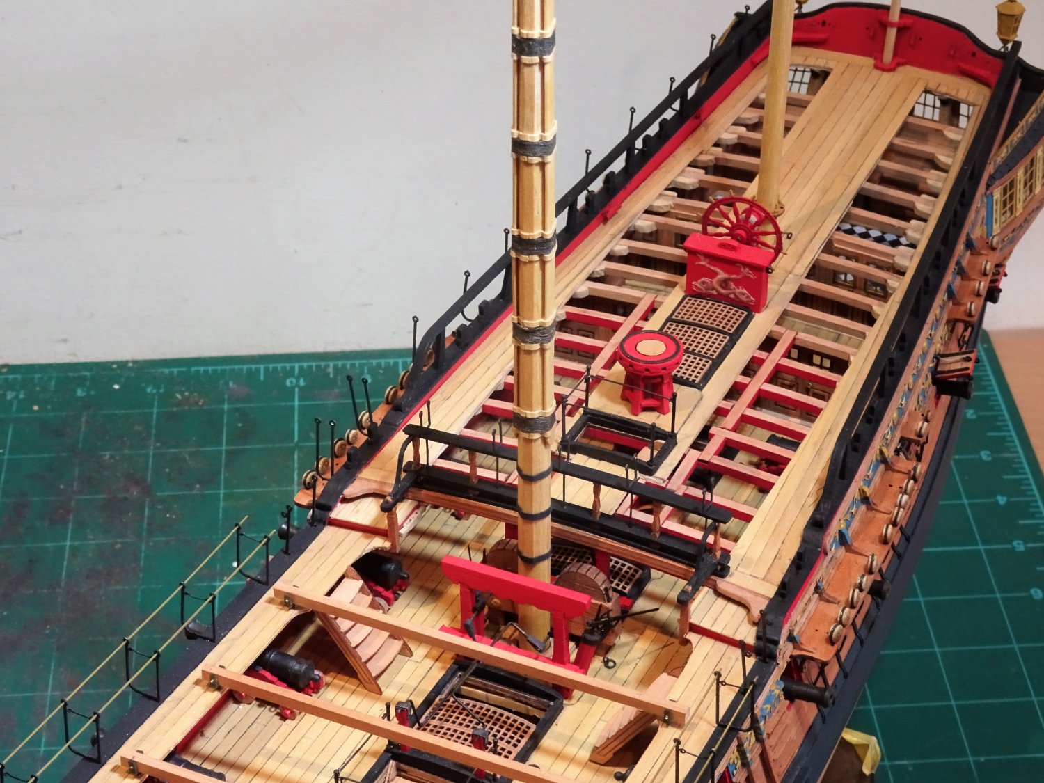
Post One hundred and Sixty-four.
While I ponder on the best way to fit the Quarterdeck Cranes, or even fit them at all, I turn my attention to the Waist Hammock cranes.
The cranes are beautifully formed and detailed brass etch fittings even down to the hooks and eyes.
.jpg.03f510057aa87a53a92e34a0298a94ac.jpg)
Amazon model
I do have the excellent example of the contemporary Amazon model which includes the cranes, and having test fitted them on Sphinx, I have decided to follow suit.
8525
My approach to fitting these cranes is to glue the foremost and aftermost cranes first and use fine brass tubing to align the holes.
I then fix the centre crane, and infill with the remainder.
Ca applied to the crane stems fixes them in place.
8518
8524
I will leave the brass tubing temporarily in place to highlight their presence and hopefully reduce the risk of knocking them as I continue to work on the model.
8534
The Foc’sle rail stanchions are location specific, and these are separately bagged, and blackened before fitting.
.thumb.JPG.9030fb56d19e8e126f3f7dc94ea48fa1.JPG)
8546(2)
8545
Cranes are fitted along the Quarter-deck breast rail.
8549
The stanchions for the boarding ropes complete the ‘ironwork’ set in this area.
Now, what to do about those Quarter deck cranes. 🤔
B.E.
24/09/2022


.JPG.1b6383cedc35beed05e1c7b76bdca6de.JPG)


.JPG.49cc717e3bd159bbe894325e720983a0.JPG)
.JPG.5a678f22ad7ab755b87051f68e45e6fc.JPG)


.JPG.ff5c6287d2c6aa4c08bf995947ce0ffe.JPG)
.JPG.7e177bfa975e6e16110c1931ed6059c2.JPG)
.JPG.975743e5b48e9ff32a6096d6e4f09084.JPG)
.JPG.73b79331e90e10f4bc5fff312a43cd5a.JPG)
.JPG.d2952ad13548ebead02bb7b751340363.JPG)

.JPG.8f4fb7f6d22a90e1470a912fc9fedb24.JPG)
.JPG.b160ee2d1662937c3191a0c2bae297ce.JPG)
.JPG.a513461ee98e8f9292f89e934c9814e0.JPG)
.JPG.91c0e970e5fa7e8a4f5eeb5bbd4afefa.JPG)
.JPG.bbd7b97e7a2556f619593f0d8cd05195.JPG)
.JPG.2247e49d03d265a3643f7b984badaa0a.JPG)


.JPG.914871f4e922b24e0c0b91822213fead.JPG)


.JPG.bcf39f9574df338896f93fb2fb890203.JPG)

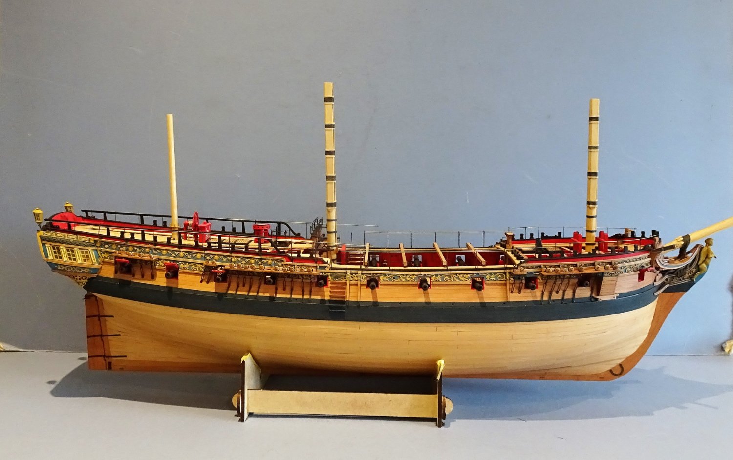
HMS Sphinx 1775 by Blue Ensign - FINISHED - Vanguard Models - 1:64 scale
in - Kit build logs for subjects built from 1751 - 1800
Posted · Edited by Blue Ensign
Thank you, Ron and Jesse,
@Ron - I just love your description of the cranes, such an image it conjures up. 😄
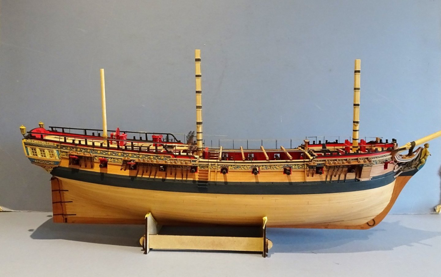
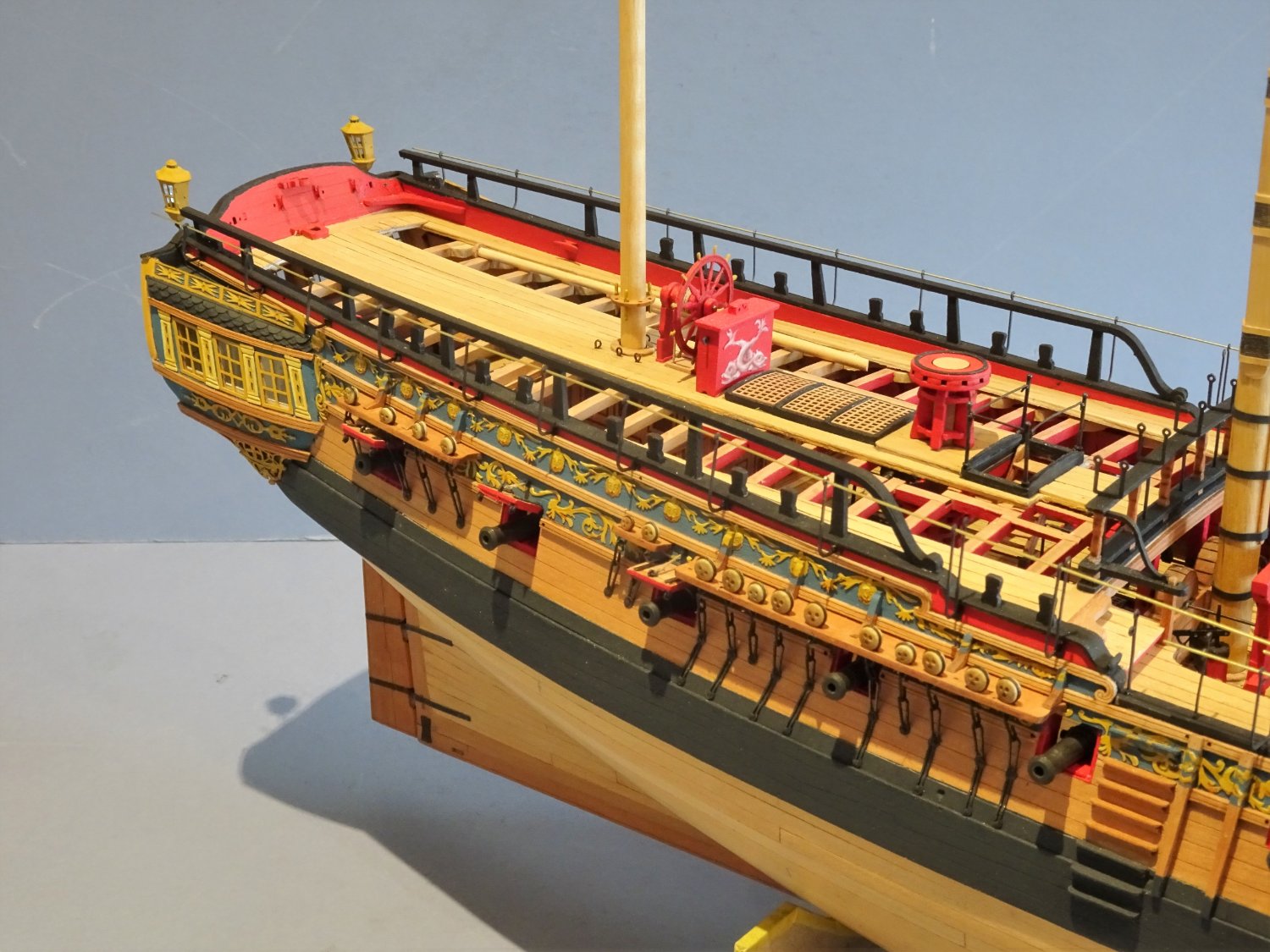
Post One hundred and seventy.
Final fettlin’
I have now reached the stage of tidying up bits and pieces, and re-checking to see if I’ve missed anything.
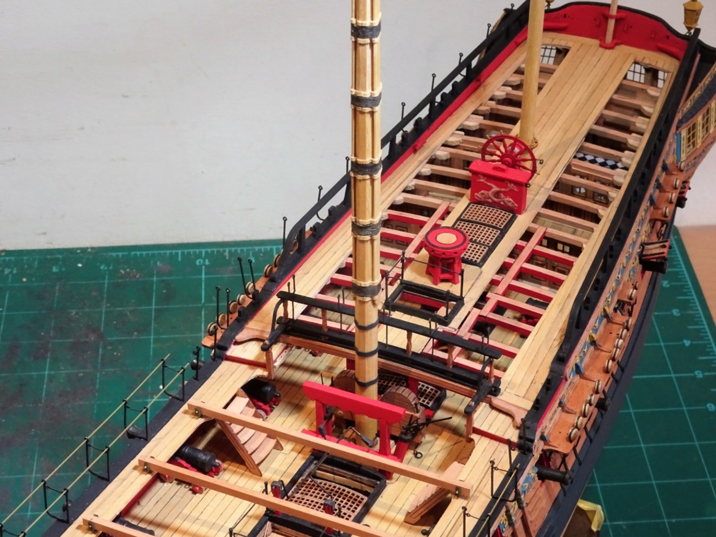
The Upper Capstan pawls are one item; I found the teardrop shaped kit versions a little unconvincing and were replaced.
8728
I followed the arrangement in the ffm Vol11 as I did with my Pegasus build.
Another decision to be made is whether to add the passing ropes thro’ the guard stanchions and cranes or leave them unadorned.
I doubt I will be able to look at the cranes in the same light again after Ron’s (hollowneck) apposite remark black prickly bits randomly popping out of her hull, an image I have some agreement with, but will probably not get out of my mind’s eye.
I used 0.31mm ø Syren line to check the effect.
I needed additional eyebolts to take some of the seizings.
8705
I added an eyebolt and secured the aft end of the quarter crane rope using false splices as the neatest option.
8709
Securing the Foc’sle passing ropes.
8726
The two double cranes at the break of the Quarterdeck are still a puzzlement, there doesn’t seem a sensible way to finish off the passing ropes on the inboard side or a clear indication of how and where they extend to.
The Pandora book drawings seem to show a line secured to the Quarter rail; the kit instructions seem to pass over this awkward little detail.
8713
Fixing of the double crane ropes.
8715
8714
A small eyebolt is fitted to the Quarter rail timberhead to secure the inner crane passing rope.
The above photos show how I finally decided to tackle the passing ropes in this area, which is my best guestimate, but I offer no guarantee of authenticity.
8712
The Foc’sle end is less problematic.
8731
8722
8720(2)
8725(2)
8723
I think on balance the model looks better with passing ropes in place, so they will remain.
I’m also finding lots of little areas needing paint touch-ins, a process that will probably continue for a while.
Then there’s the dust.🙄
B.E.
09/10/2022
Night of the Hunters Moon 🌕