
.JPG.ca33079f5815b861e67b9c2cccd37982.JPG)

Blue Ensign
-
Posts
4,286 -
Joined
-
Last visited
Content Type
Profiles
Forums
Gallery
Events
Posts posted by Blue Ensign
-
-
Post Nine
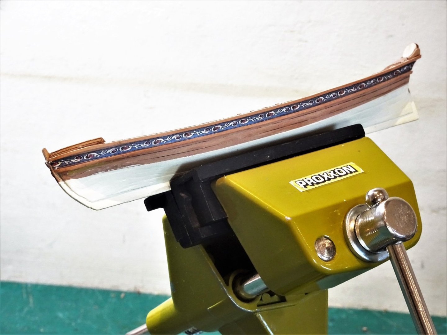
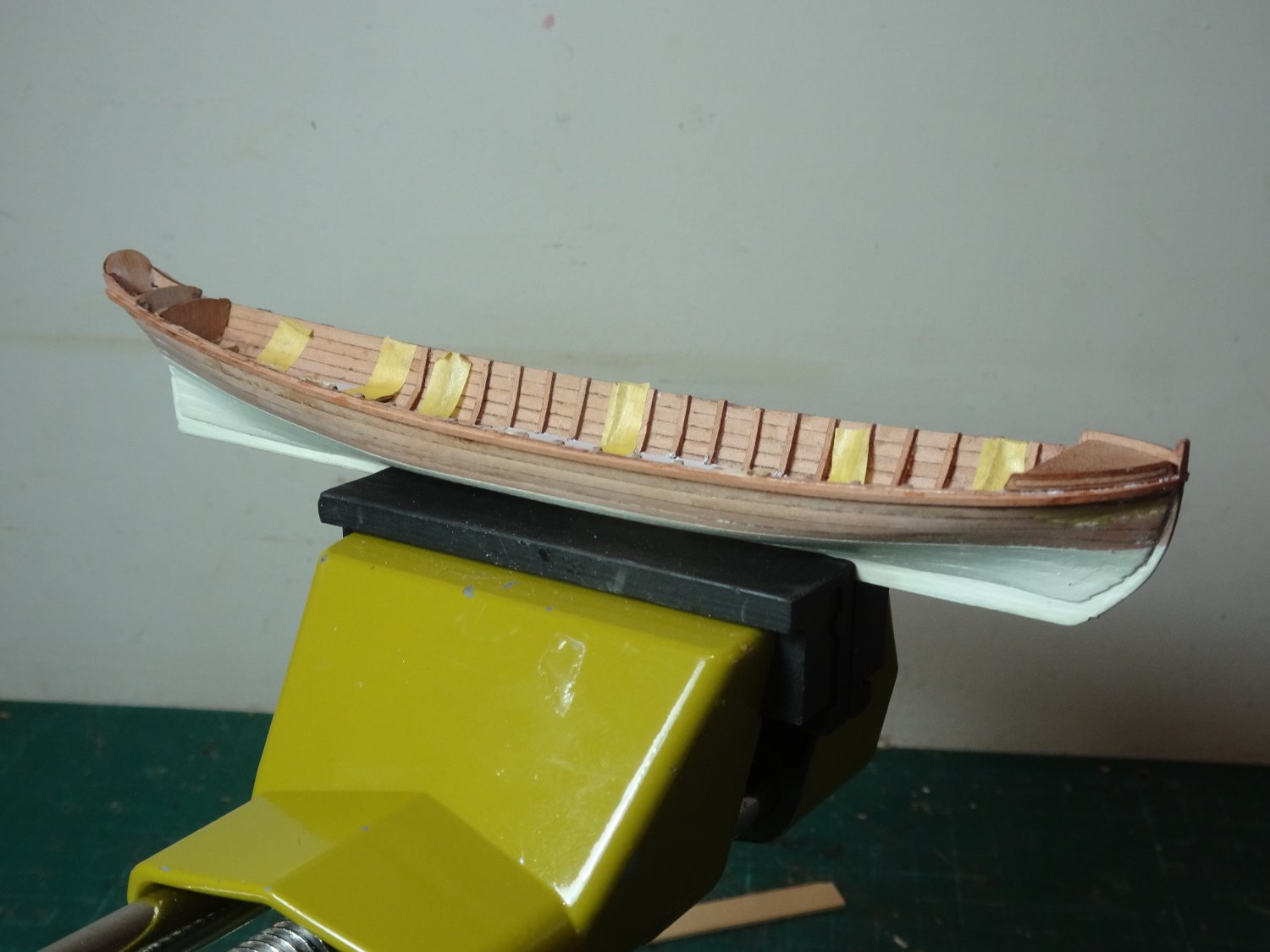
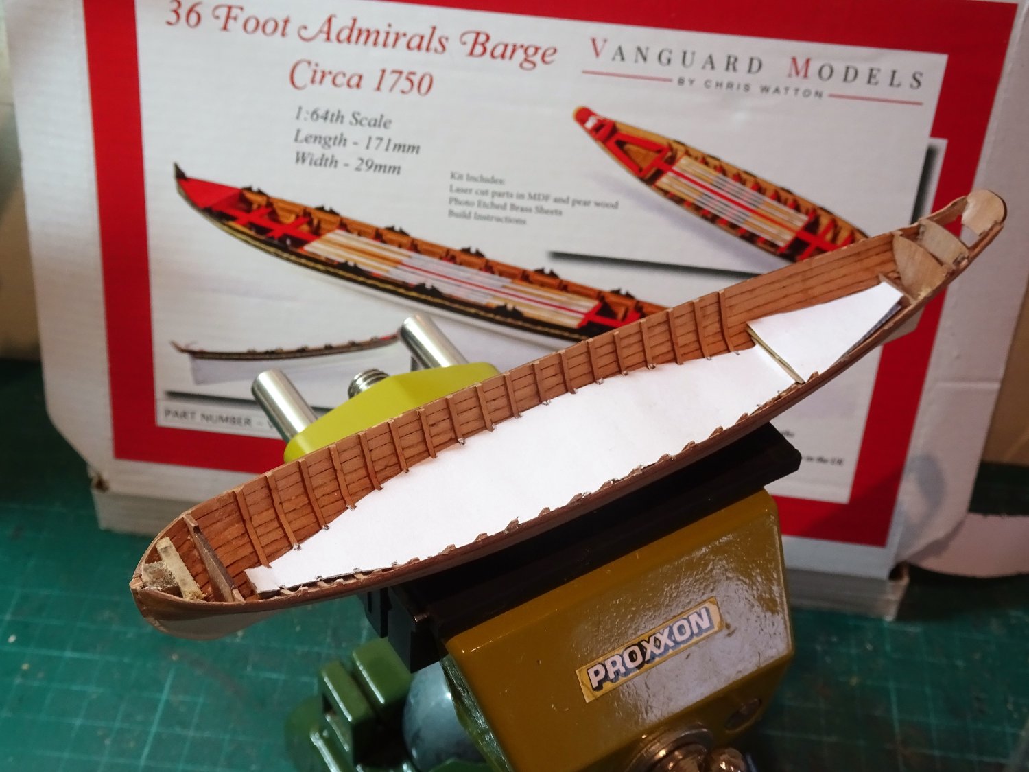
At this stage I am departing from the suggested build sequence, to work on the outside hull.
The kit arrangement involves using spare hull planks to form rails between which a frieze decoration (brass etch) is fitted.
To my eye the 2x0.8mm strips look a tad heavy and I have opted for 1mm wide strips to represent the rails.

9434
The top rail is fixed level with the gunwale, follows the sheer, and extends to the flying Transom. The rails are fixed using spots of ca.
9450
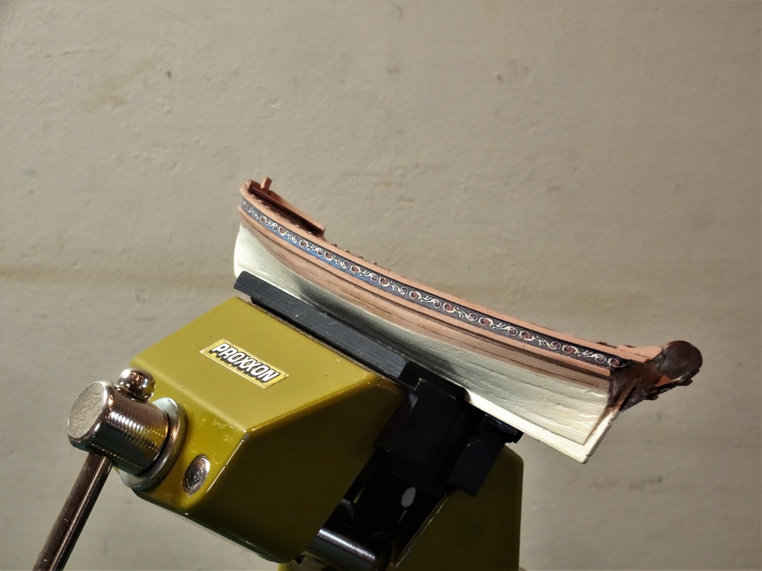
A paper frieze pattern is used in preference to the etched frieze. This is simply printed on 90gsm printer paper, sprayed with artists fixative, and glued using slightly diluted pva.

9452
The lower rail is then applied following the pattern line and terminates at the transom proper.

9449
I think this arrangement gives a better scale appearance.
9446
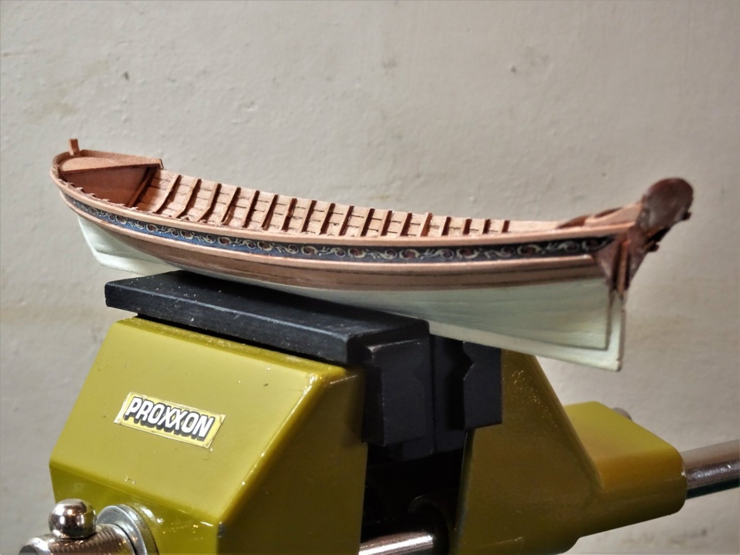
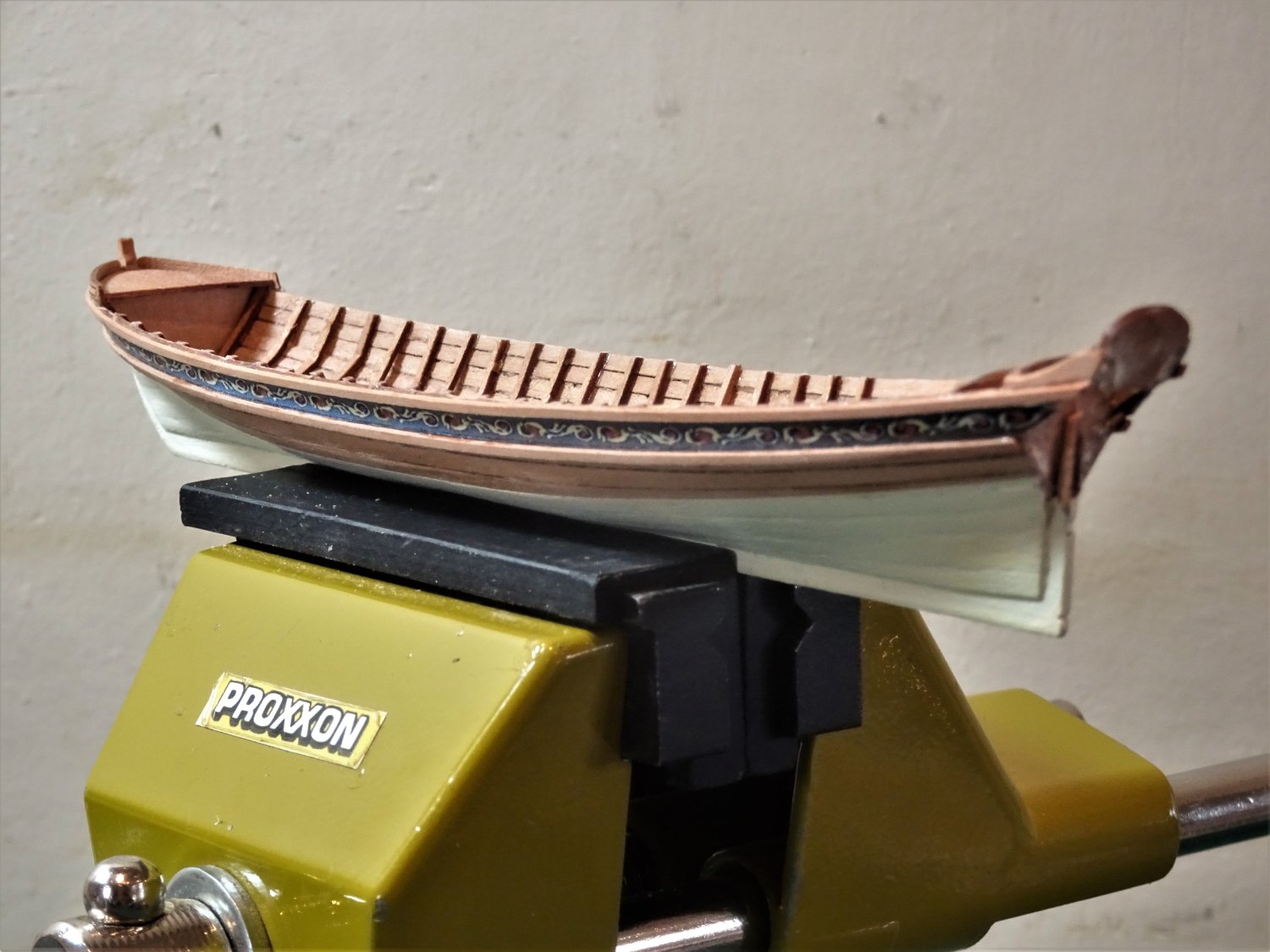
With the rails in place, I can now tidy up the lower hull and fix the waterline.
The macros also reveal that some of the ribs need a little attention.
B.E.
19/11/2022
-
Thank you, Yves, Jim, and Andy.
@ Andy, - good spot, but I was aware, it was easier to go with the grain for cutting out, and the deck is to be painted.
Cheers,
B.E.
- bruce d, realworkingsailor and mtaylor
-
 3
3
-
Post Eight
I took the obvious and simple approach.
9397
The bulkhead was faced up with a piece of 0.6mm Pearwood sheet.
9404
A new platform was cut out of the same stuff.
9405
The plank lines were lightly scribed into the surface.
 9410
9410
Wash boards will be fitted around the edge.
9412
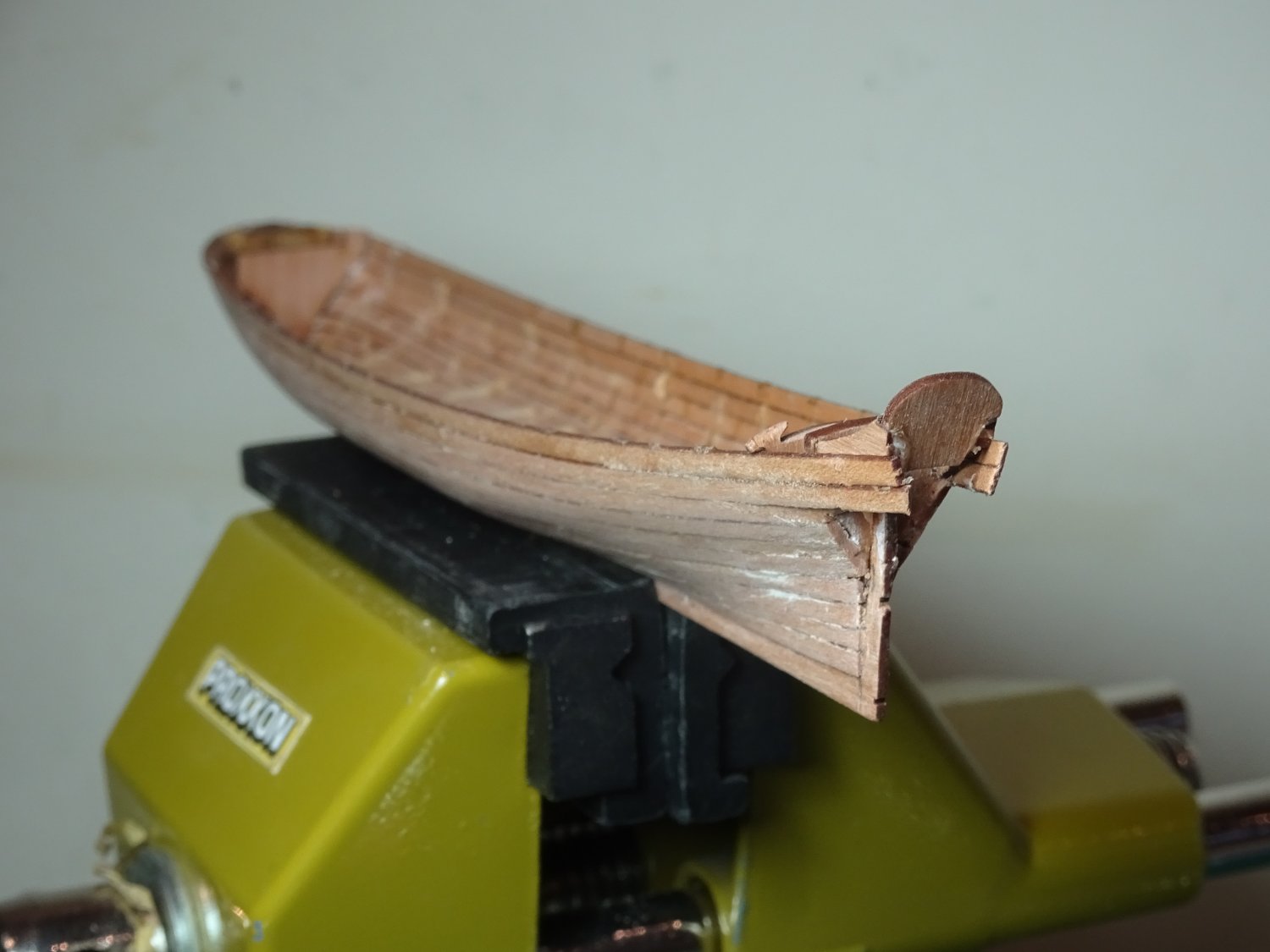
I still can’t help feeling that the fore platform should sit below the gunwale level.
Every contemporary model I have seen shows this, as indeed does the Vanguard Pinnace kit in the same series.
I did wonder if I had somehow made a mistake in the build, but the kit photo’s show pretty much the same result.
I can’t contemplate chopping out the bow bulkheads to lower the platform, I fear it would put too much strain on the delicate construction, so we are where we are.
.thumb.JPG.84b48e3ceb363df0241d31ecd2a3ac11.JPG)
9414(2)
The final option is to add wash boards which go some-way to redress the balance and give a more authentic look, but it is a compromise.
.thumb.JPG.ed5af25071051589c2cc870152f318fe.JPG)
9415(2)
I happened to have some spare wash boards from the Yawl kit.
9429
The detail devil in me can’t help noticing one other anomaly.
The first thole pins are shown adjacent to the fore platform, at the same level.
It was not uncommon for the first rower to sit on the platform but with the kit configuration the rower would be above the tholes which makes no sense.
This is an attractive model, and perhaps many will care little about the details I have highlighted. Some may say at 1:64 scale it is sufficient for the purpose.
I would, however, urge Chris to re-visit this kit, re-design the first two bulkheads to lower the platform to the same level as the thwarts (as per the Pinnace kit) and reconfigure the oarlocks to single banked rowing on each thwart.
‘nuff said, on with the build.
B.E.
18/11/2022
-
Post Seven
The gratings are secured in place using tiny spots of ca but I have found with my previous small boat builds that small enough not to spread thro’ the gratings with an annoying shiny reflection, is not always sufficient to hold securely, we shall see.

9395
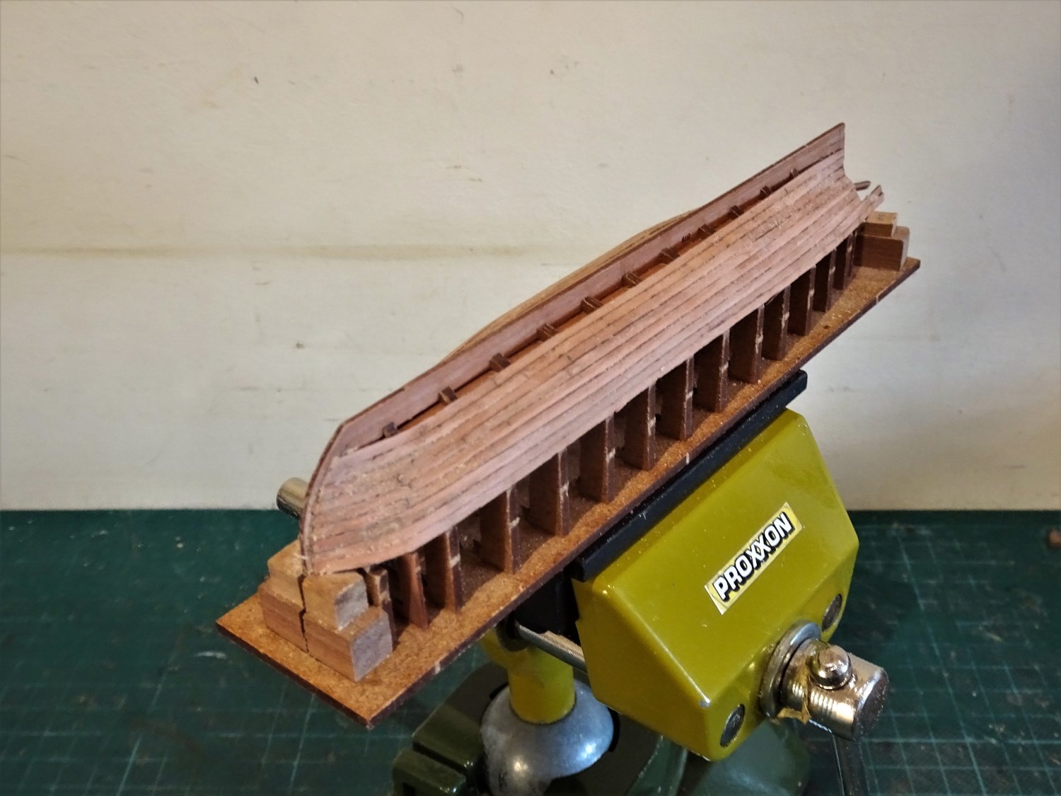
I took the precaution of cutting a pattern to fit over the gratings to protect the surface during the extensive messing around inside the boat to come.

9394
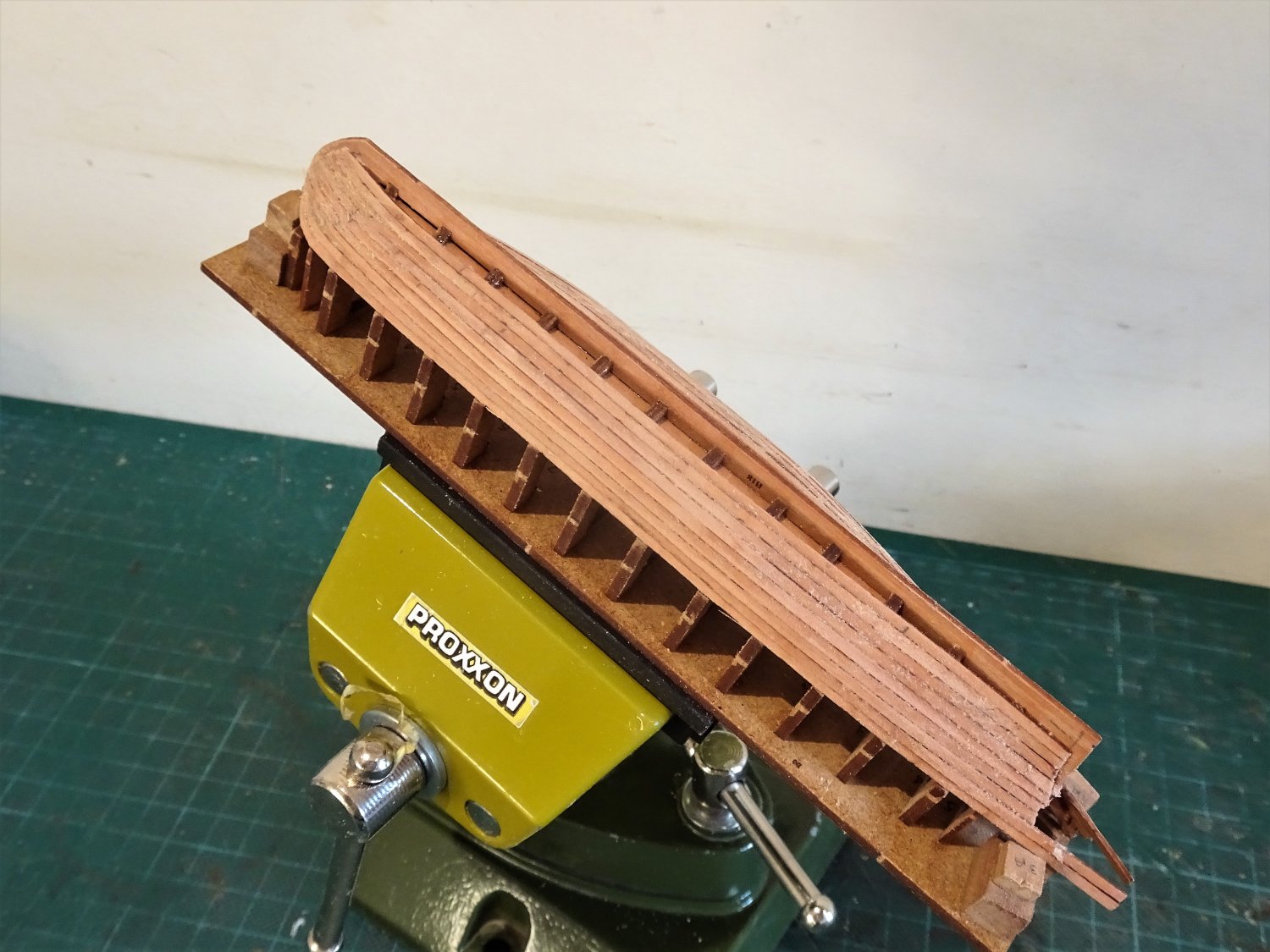
The ribs are easily fitted given the notches in the grating pattern, and they do stiffen up the hull.
.thumb.JPG.f393276319c3cca7cce6c689af7eb096.JPG)
9393
There is an adequate supply of strip for this purpose.
There are one or two little bits to fit as per sections 32- 35 of the blurb, but back in section 13 there is a part B25 indicated, which as far as I can see is not mentioned again.
.thumb.JPG.e9cdc87d637c5c3851f9331a85cbb53d.JPG)
9389(2)
I suspect it may have something to do with the Foredeck but If it is, I think the instructions need re-visiting to be more specific in this area.
.thumb.JPG.b7afd6a754b2fd7add19e3d8bfdbb2c3.JPG)
9388(2)
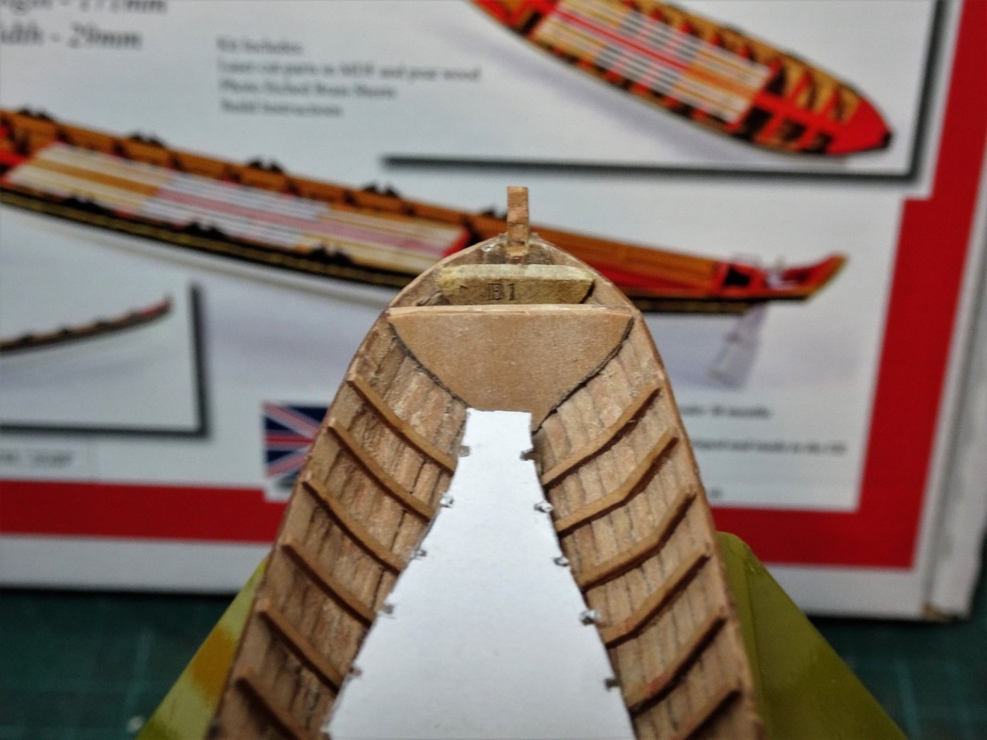
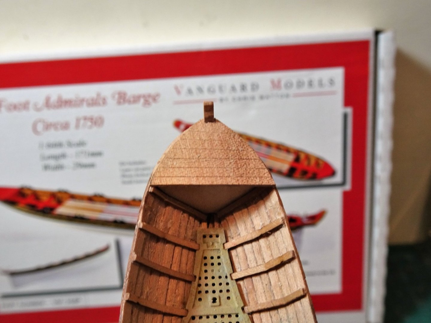
It’s not an easy match in any case, and the foredeck fitting has issues. If the notched back edge is intended to slot into the second bulkhead, then the first bulkhead should sit below the gunwale.
.thumb.JPG.7d0d780d0f84c71081d3ccf2e4cd2371.JPG)
9292(2)
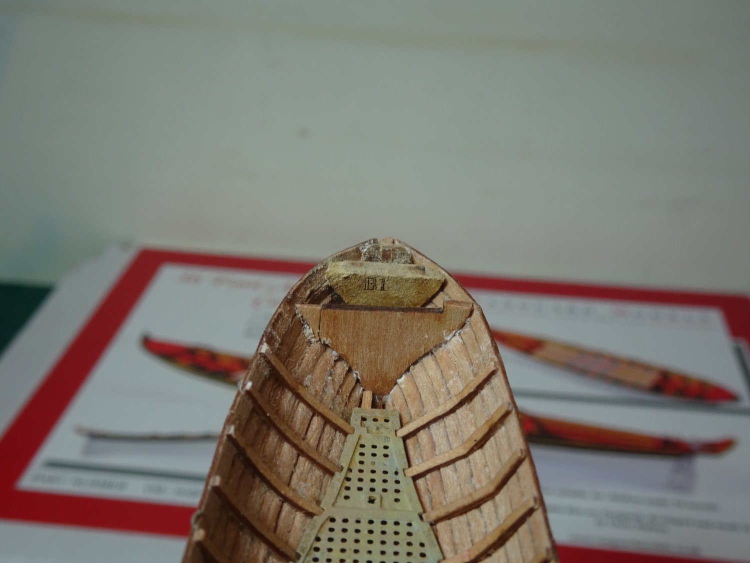
The first bulkhead and bow pieces are level with the gunwale.
(The bow stem extension has broken off, but that is easily fixed.)
9393(2)
This bulkhead, from the photos appears to form the vertical face of the fore platform.

9390
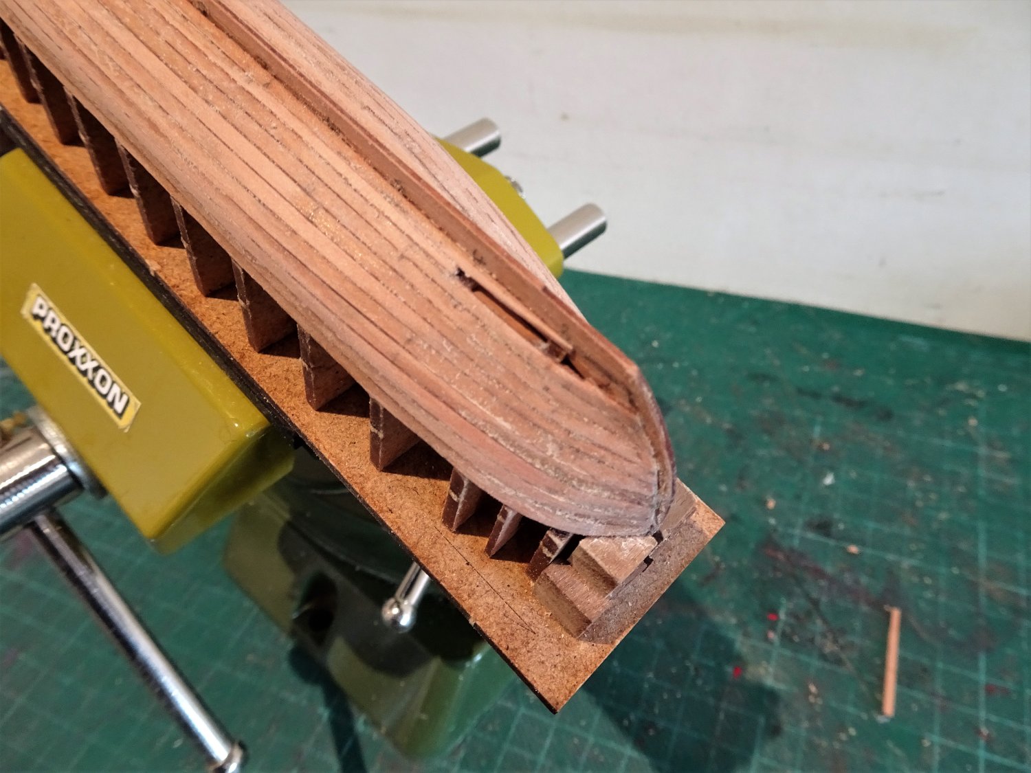
This rather unflattering macro of the bow end demonstrates the issues.
(Part of the Pearwood bulkhead on the port side snapped off during trimming.)
The problem is how to model the fore platform.
To use part B25, the first bulkhead would need to be rebated to accept the part, not an easy task at this point.
My thoughts are that the second bulkhead be infilled and brought level with the first bulkhead, and a piece fashioned to fit.
If this stands a tad proud of the top line planking, it can be used to support a bow wash strake.
I need to ponder this awhile, but until it’s sorted, I can’t really move forward with this build.
B.E.
17/11/2022
-
Thank you, Allan,
The kit is set up for double banking on alternative thwarts which seems unusual.
I will be adopting the single banked arrangement as shown on the contemporary model (1750) above.
ps: It is interesting that the model NMM SLR0489 is described as having twelve crew rowing double-banked.
To my eye they are rowing single banked, unless I have misunderstood the terms all these years. 🤔
The other anomaly is the barge is shown flying the Royal Standard which struck me as a little odd.
Still the model is very nice, and one I am using as a reference.
B.E.
-
Thanks Jason,
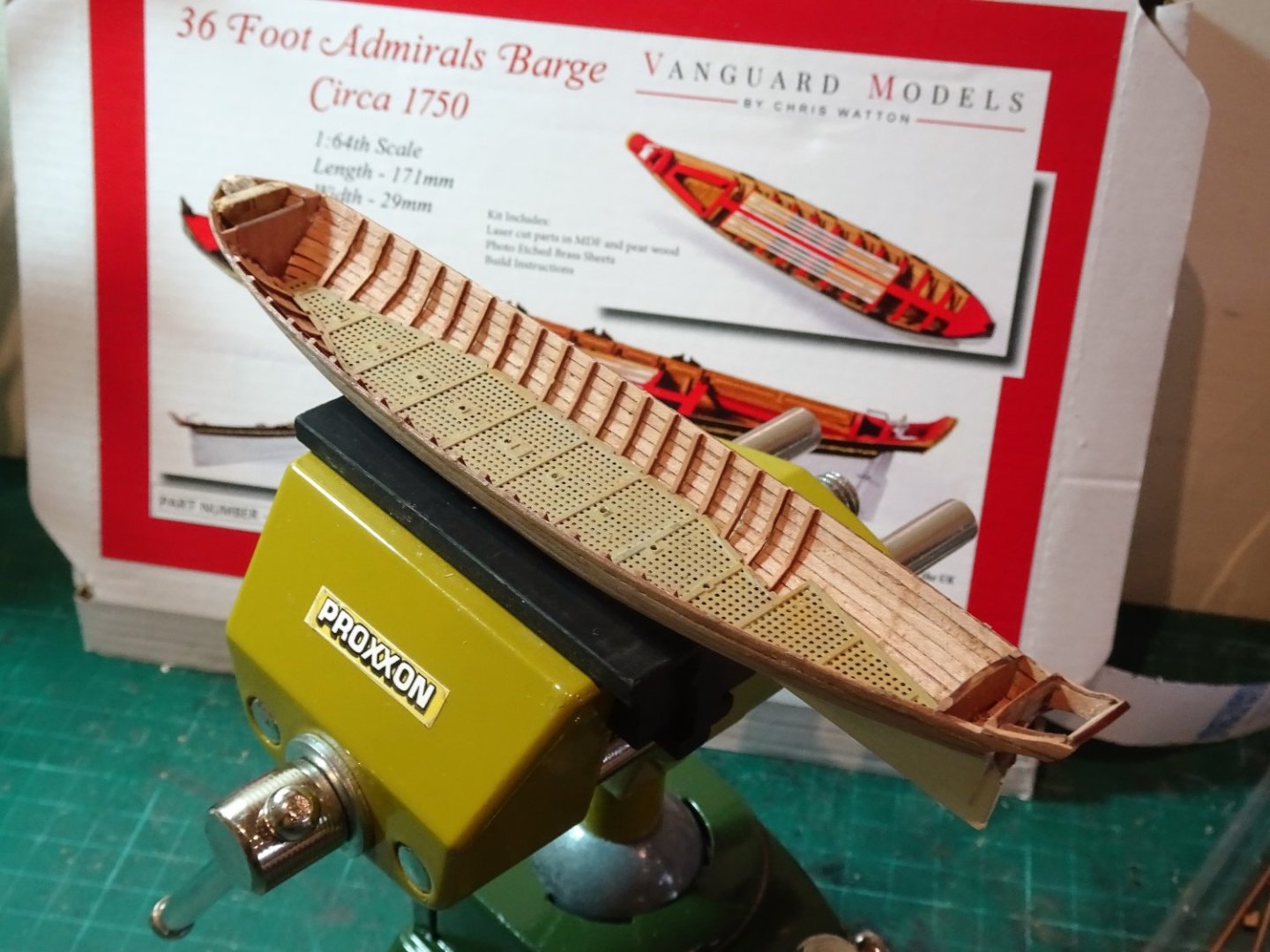
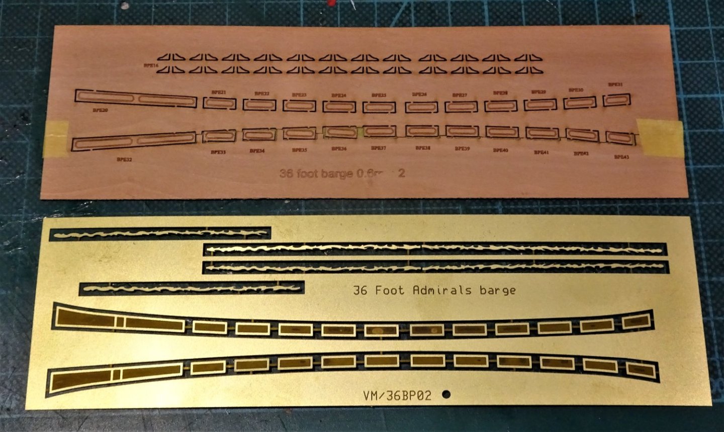
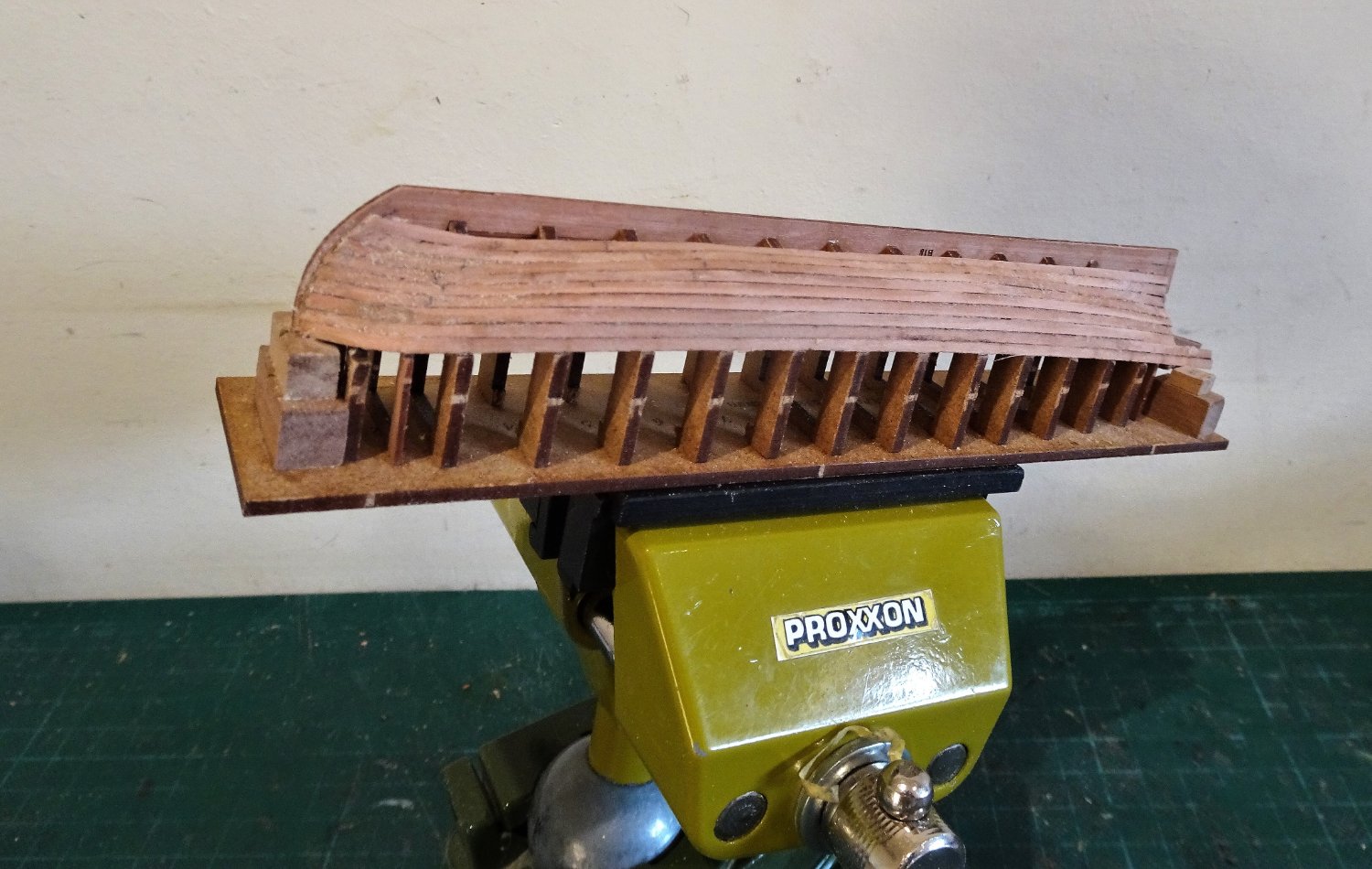
Post Six.
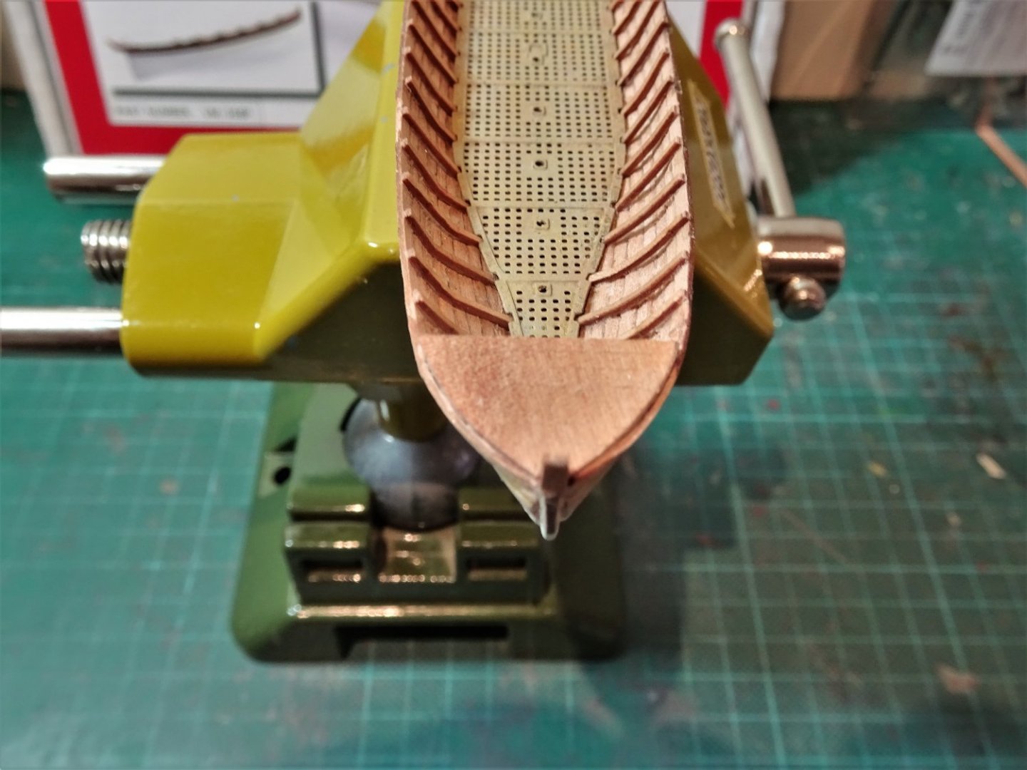
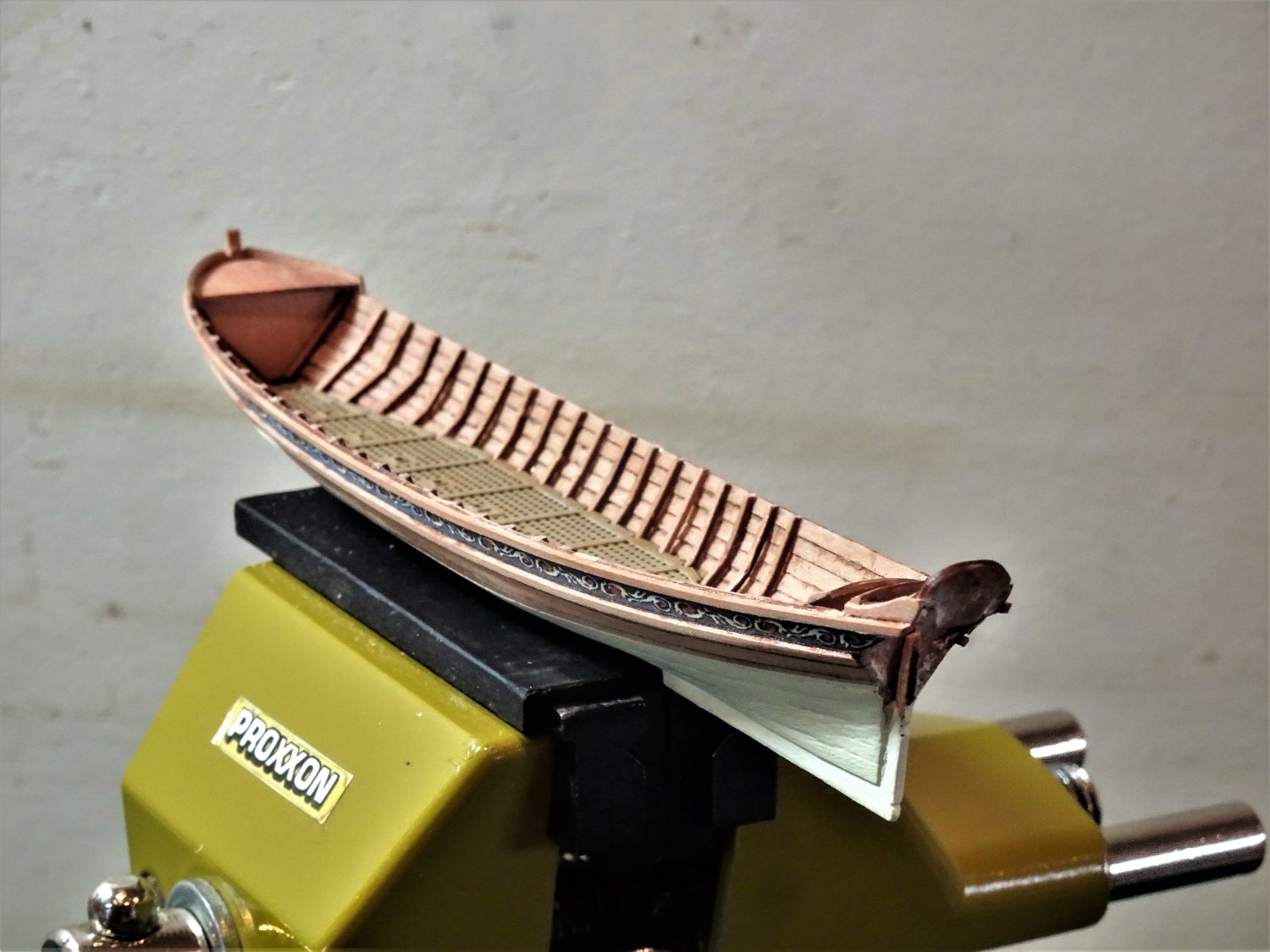
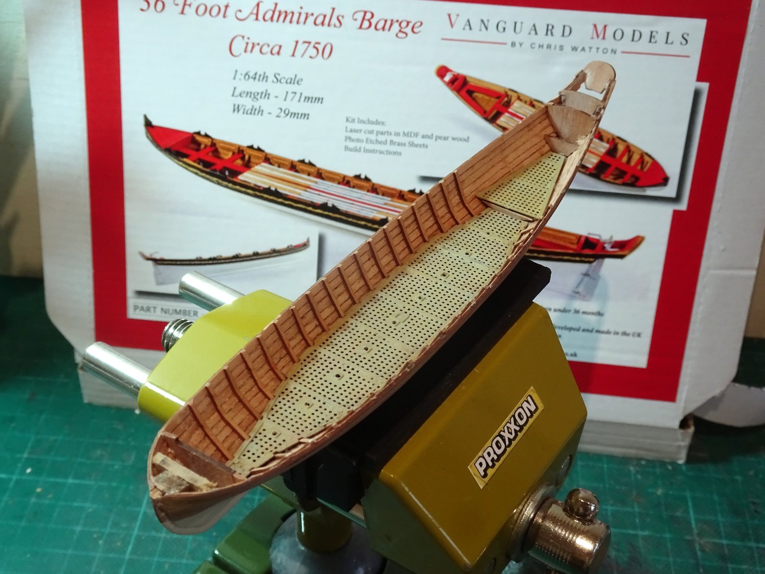
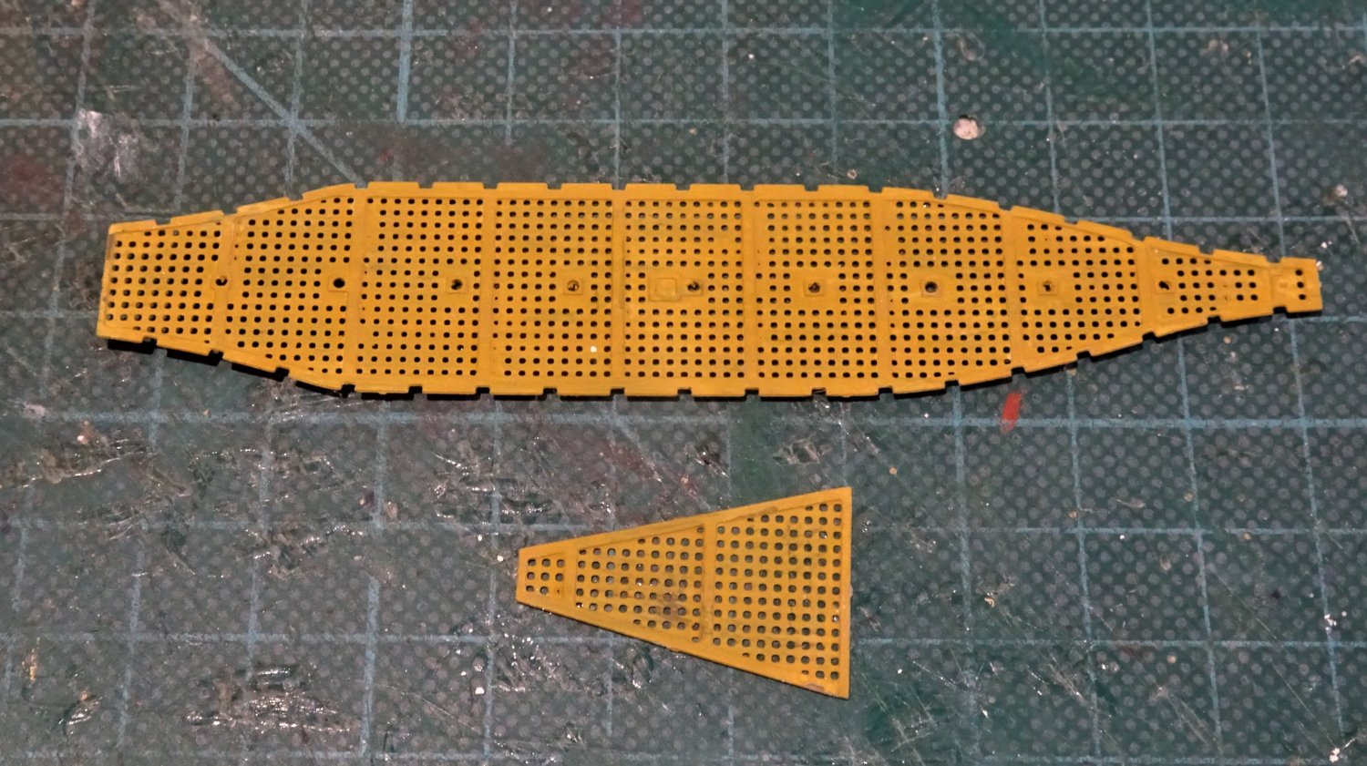
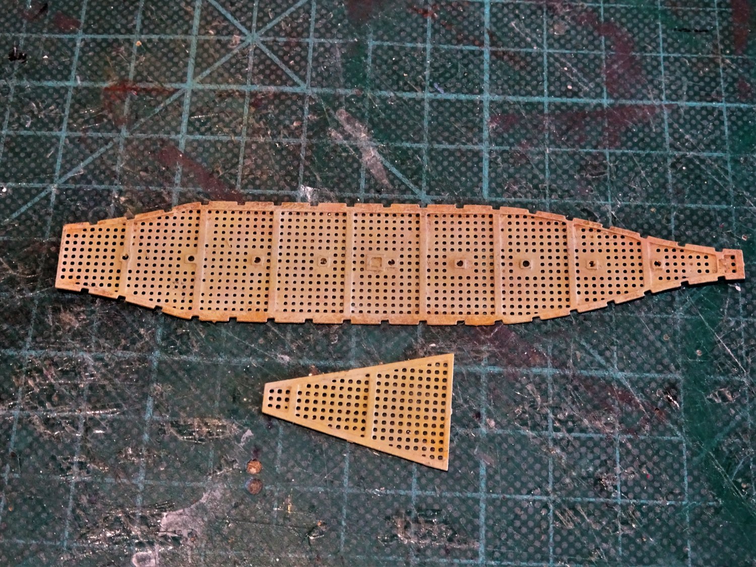
In this post I have concentrated on preparing the Foot-waling, which for kit purposes is represented by brass etch gratings.
Traditionally, based on contemporary models, barges were boarded out, but I have decided to use the provided pieces, not least because the central bench support pillars are marked and drilled for insertion, which makes things a lot easier.
The gratings are also pre-notched for the insertion of the frames, an excellent idea which saves the hassle of spacing calculations and positioning.
Using the etch does mean that the gratings must be painted to replicate wood.
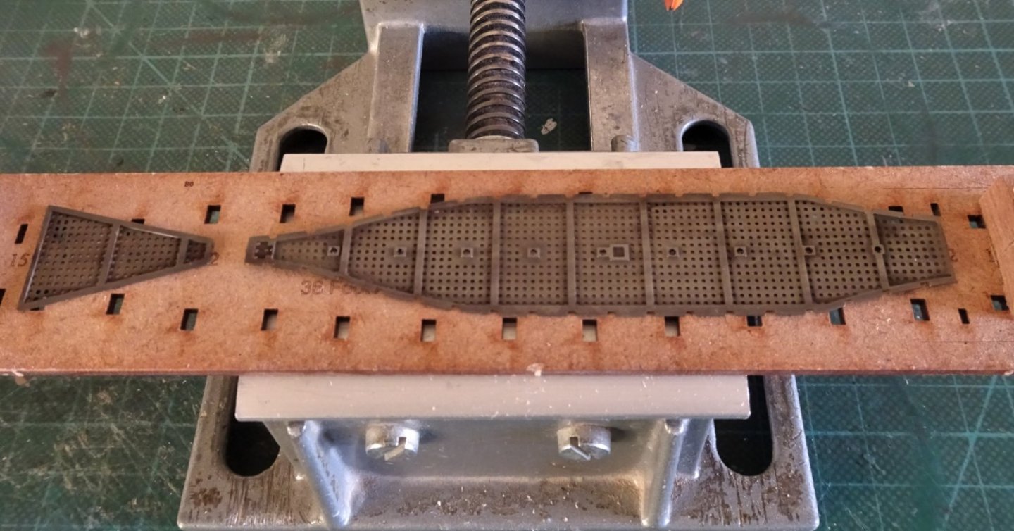
9364
My approach is to chemically blacken the etch which provides a good key for subsequently painting.
The blurb gives a method to follow to achieve the finish and is broadly how I do it.
I am using Vallejo paints throughout.
A base coat of dark sand, which is light in colour, is applied.

9366
Second coat of Ochre Brown.
Too yellow for my eye, I had in mind a more scrubbed wood look.

9381
To this end a mix of Ivory/ slightly coloured with dark sand and a spot of Black/grey was mixed almost full strength and stippled on with a dry brush.
Getting there, I think.
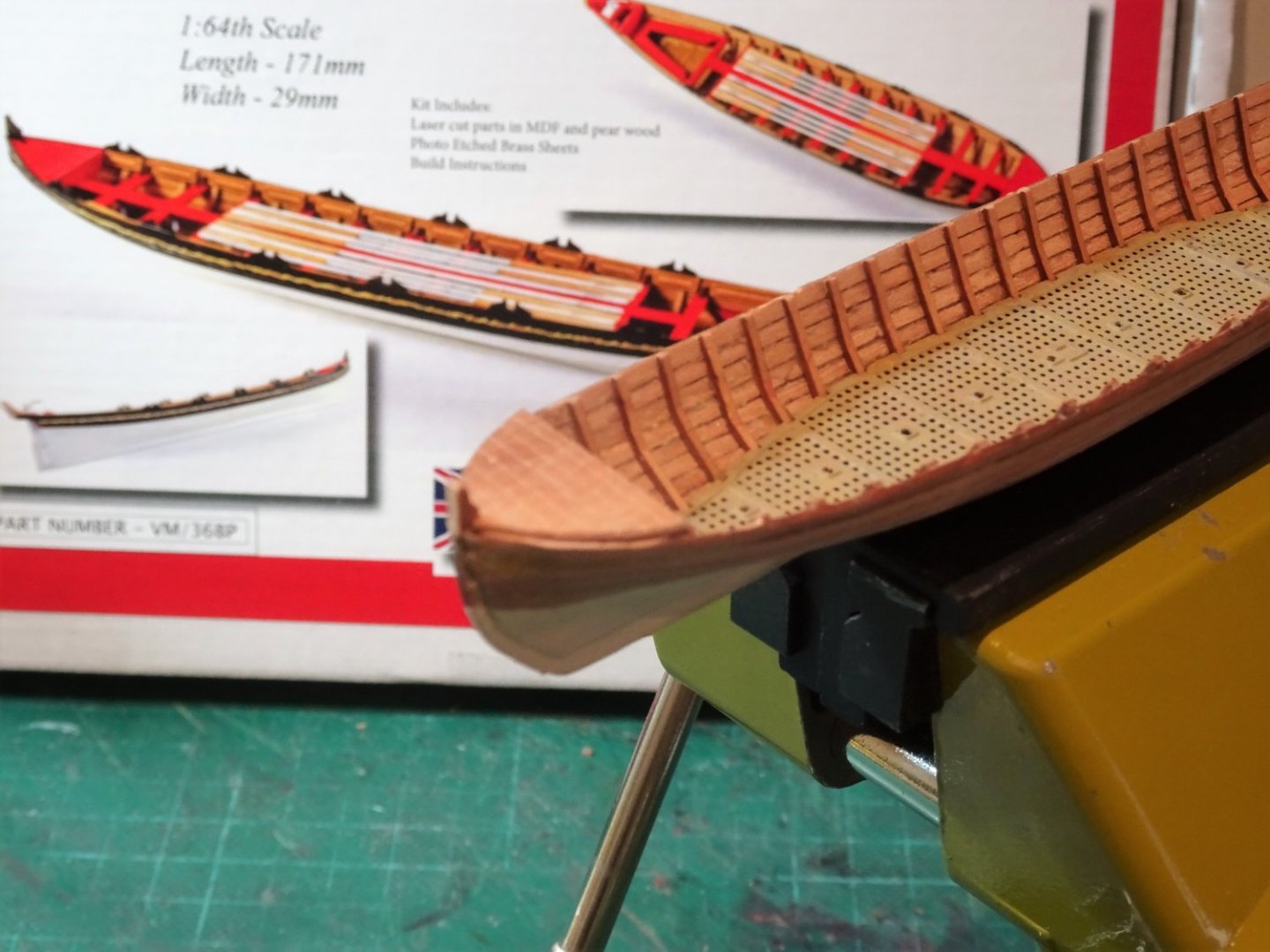
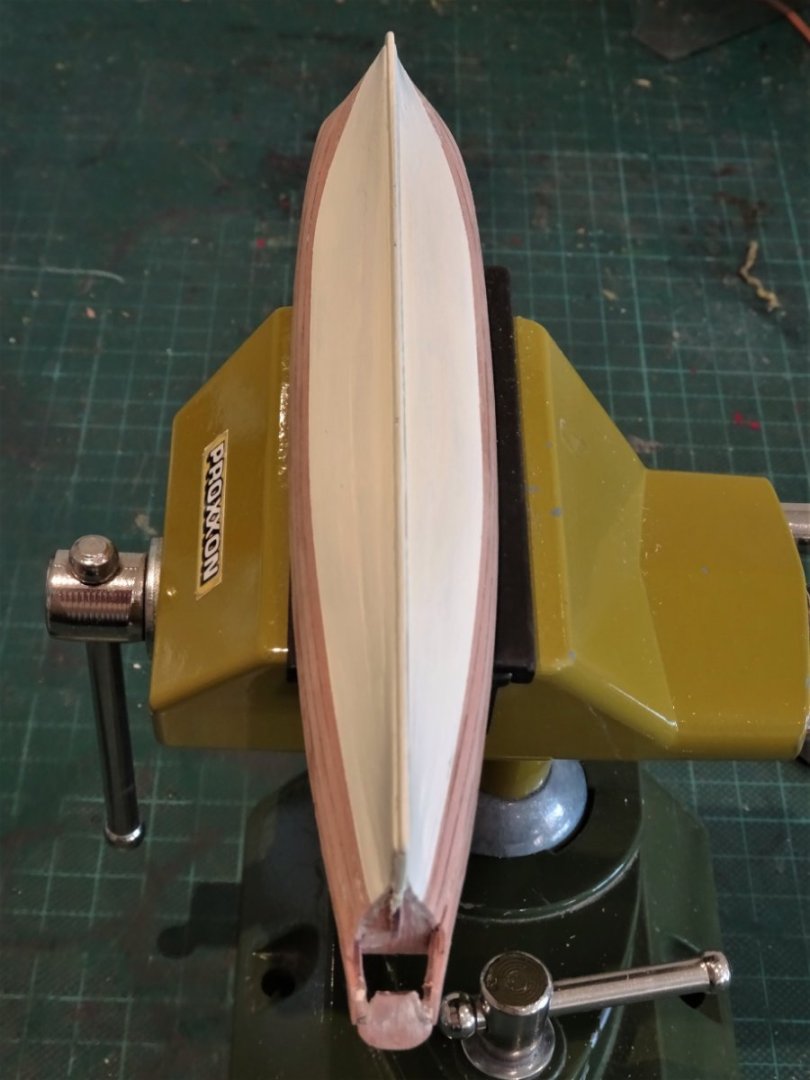
The kit scheme indicates painting the hull white up to the top three strakes, which then contains the rails with the painted frieze between.
I prefer the look of bright work between rail and waterline, and I applied a couple of paint coats both to gauge the line and highlight any areas that need attention on the lower hull.
9367
9370
I have used ivory for the lower hull, which I think gives a more scale look.

9379
This is not the end of the lower hull painting, but I think I have the waterline about right, and this will be re-visited later.

9375
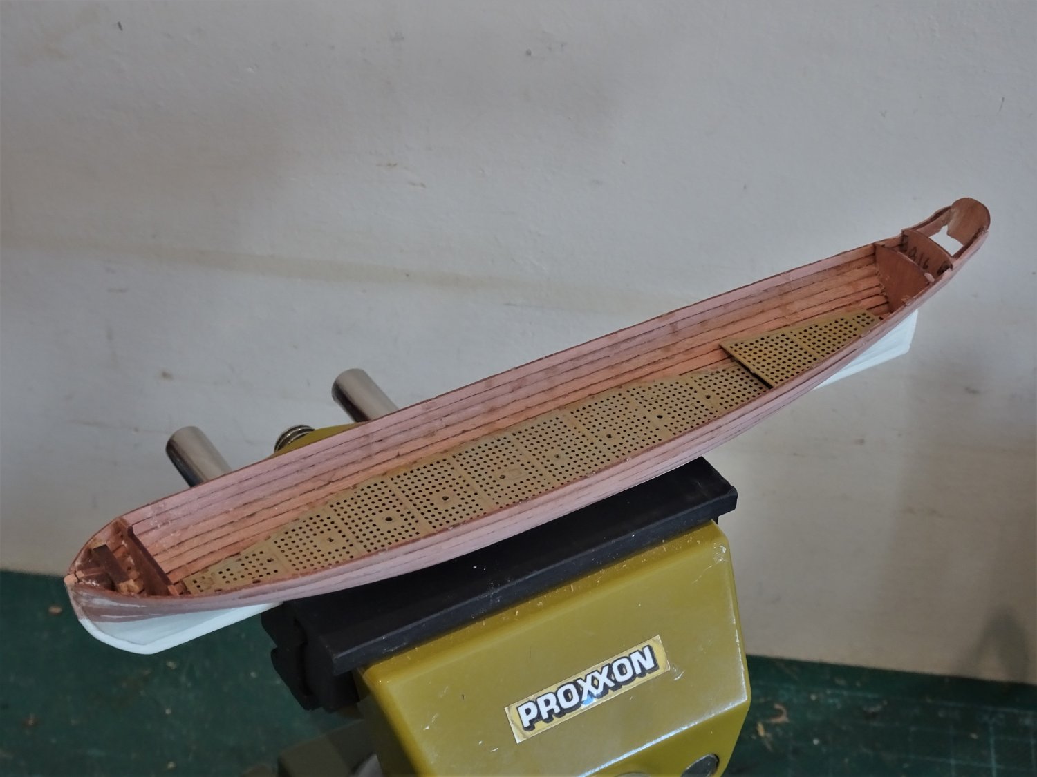
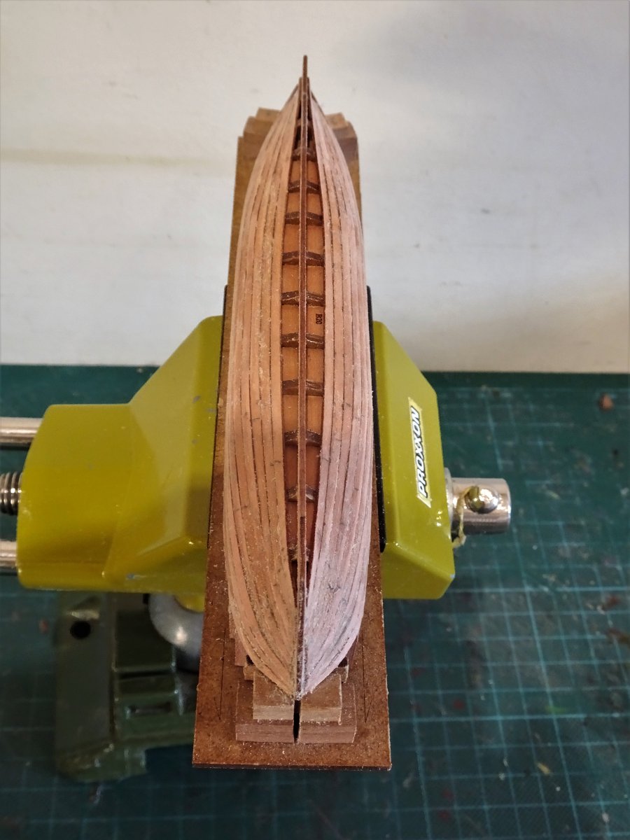
The internal hull has been cleaned up and I am fairly happy with the gratings look.
The next stage is to fix the gratings in place and fit the ribs.
B.E.
16/11/2022
-
Seamanship in the Age of sail by John Harland gives the complete process from getting underway from anchoring, to coming to anchor, and stowing the cables.
A very useful book.
It is exhausting just reading about handling the cables; cleaning and setting them to dry before stowage, and the highly skilled task of passing them down to the hold and faking them in the correct manner for subsequent use.
B.E.
-
-
Post Five
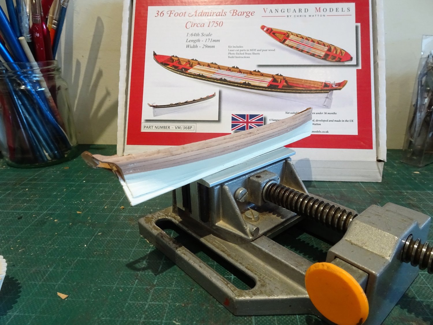
I continued to use the provided strip for the planking and there is more than sufficient for the need.
A representation of the Garboard is fitted first, followed by a final spiled plank.

9331
I terminated this one on the third bulkhead leaving just the forward part that meets the stem and abuts the Garboard.
A drop plank of sorts was then formed to complete the planking.
.thumb.JPG.49f069882976273861f27d8d3e6a5fcc.JPG)
9332
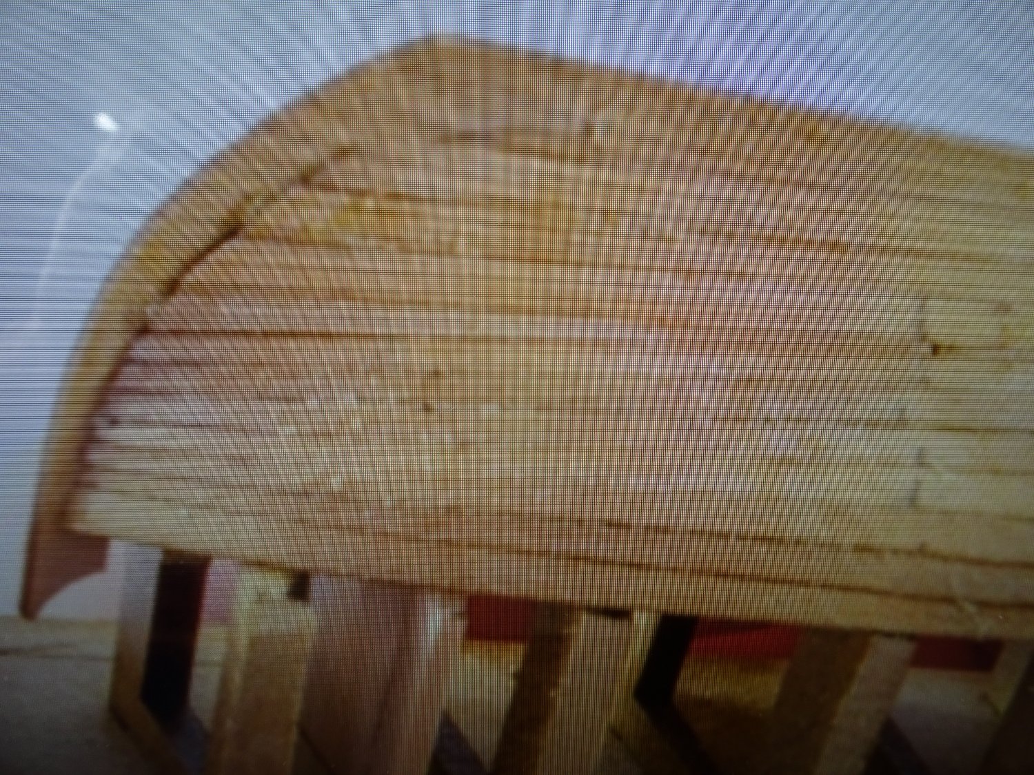
I didn’t get away without a little filler in the bow area, but once the frieze is added, along with rails, and the waterline is painted in, it should look ok.
.thumb.JPG.39c4e2e0e1d8b62a3195282f7e3d294f.JPG)
9335(2)
.thumb.JPG.8d1686998c2bb16509c59f5688d5a7cf.JPG)
9341(2)
With the bulkheads twisted away there is not too much cleaning up to do.
.thumb.JPG.9351e8cba84715a71c3bba49bb329631.JPG)
9345(2)
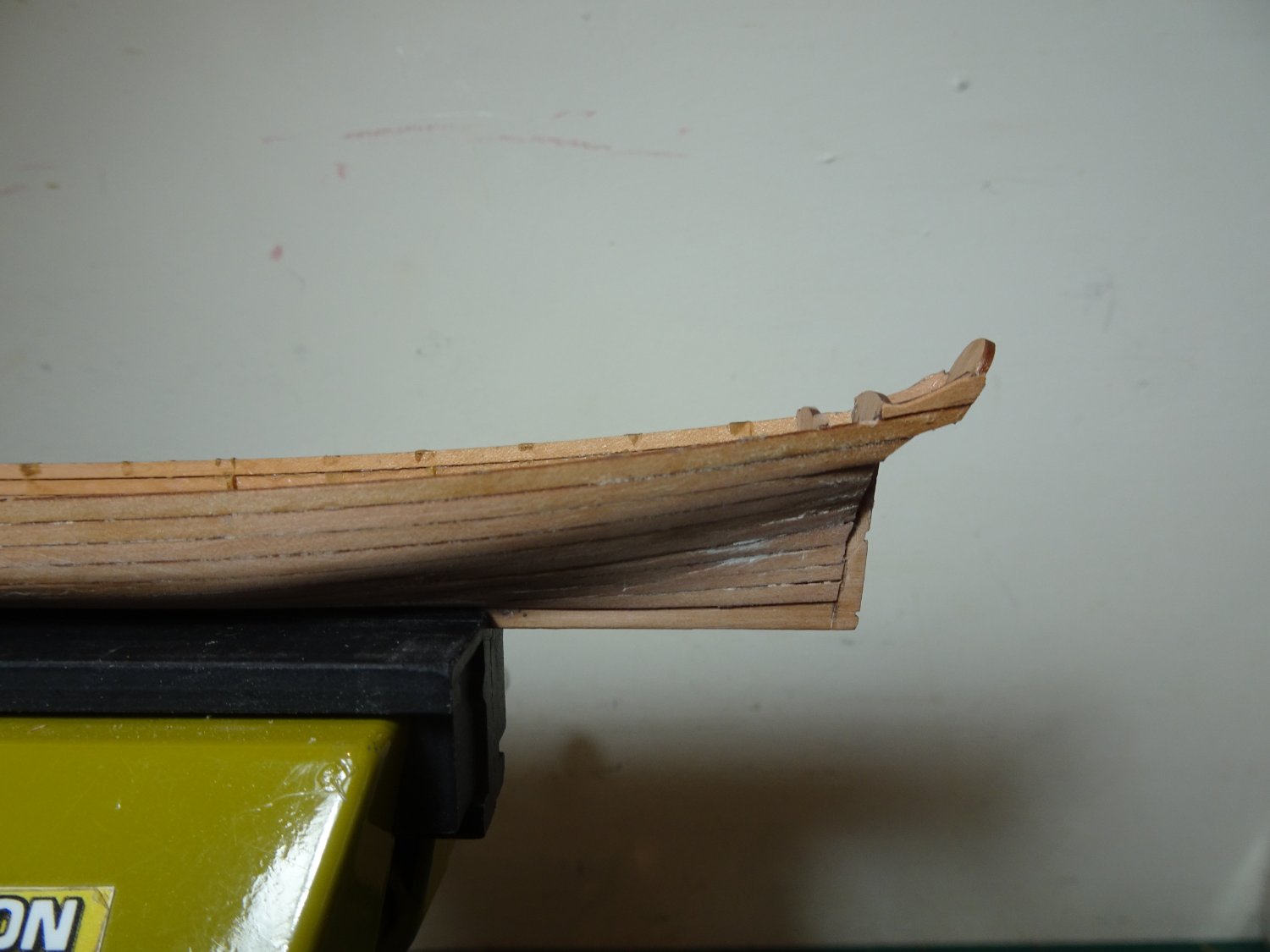
During construction the Flying Transom detached so this needed to be re-fixed.

9339
There is a lot of fettlin’ to do to shape the extended planking to conform to the Flying Transom arms.
The aim is to achieve that elegant sweep typical of Barges (and Pinnaces)
I think a few extra photo close-ups would have been helpful in the blurb to show the set-up more clearly.

9350
An additional planking section is required to be fitted over the arms, and shaped. (still w-i-p)
.thumb.JPG.9283da3a26e8c350d8e3ea21b6e35ef1.JPG)
9358(2)
A brass etch transom panel is provided, but there are no photos of this in place, and it is not mentioned in the blurb.
.thumb.JPG.aebb3dd2b2d7aeb8ee5fe2239b350864.JPG)
9361(2)
I have decided not to use it except as a template to make a wooden version on which an appropriate design can be applied.
The macros are brutal at this stage, but with a fair wind and following sea hopefully a silk purse will emerge from this sow’s ear.
Onwards,
B.E.
15/11/2022
-
Well expressed, Jason,
It is a useful tool to set down one's reasoning both to help formulate approach and answer those 'why did I do that' moments some way down the road.
I think your choice is spot on, but there is always wriggle room with this sort of thing; between plan, Admiralty order, and fitting out I suspect that in reality there was an element of 'availability' involved.
No one is going to gainsay you as you have worked using contemporary evidence, personally I like the four-carronade configuration.
B.E.
- Beef Wellington and AJohnson
-
2
-
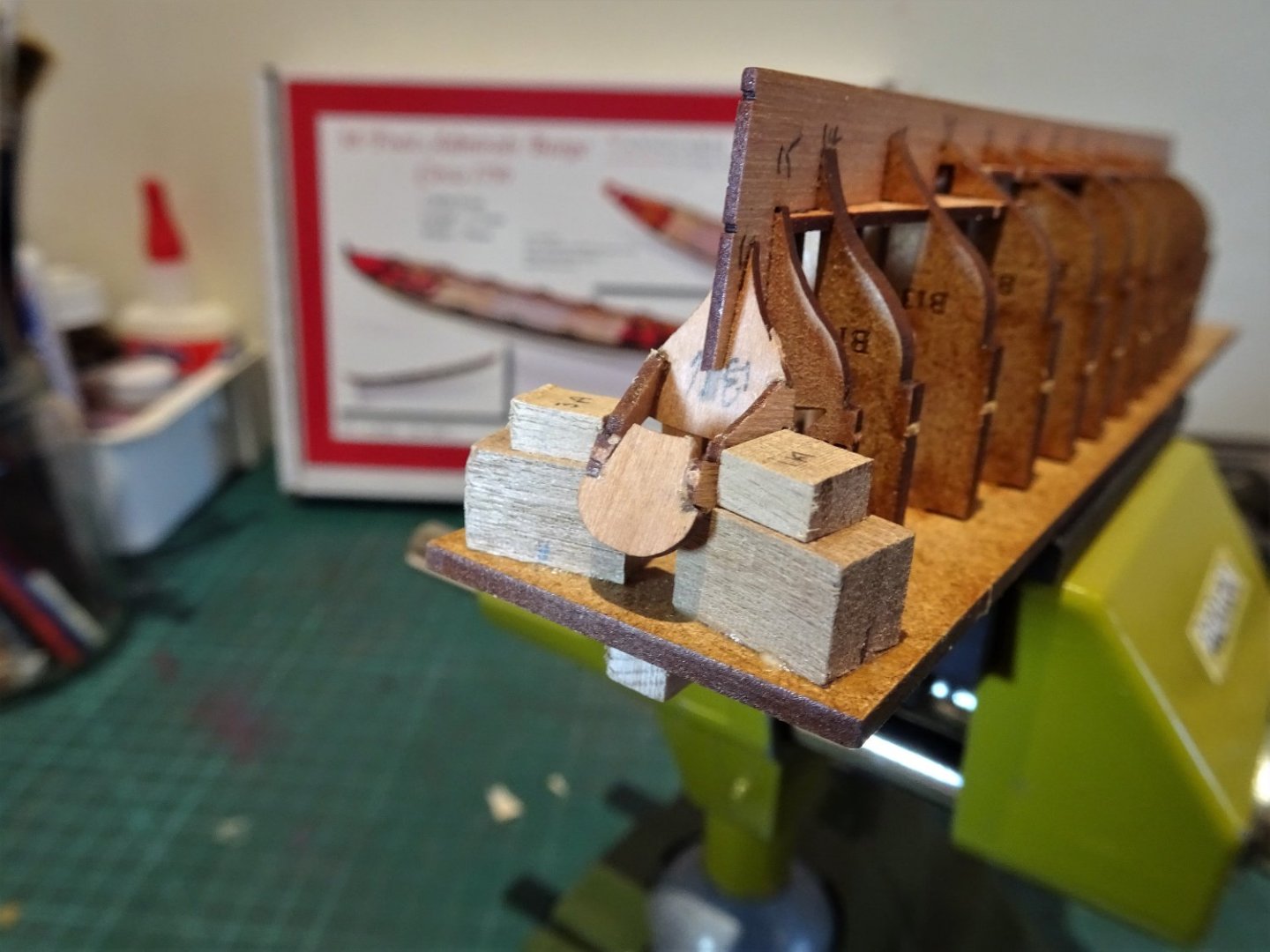
Post Four
Planking and more planking.
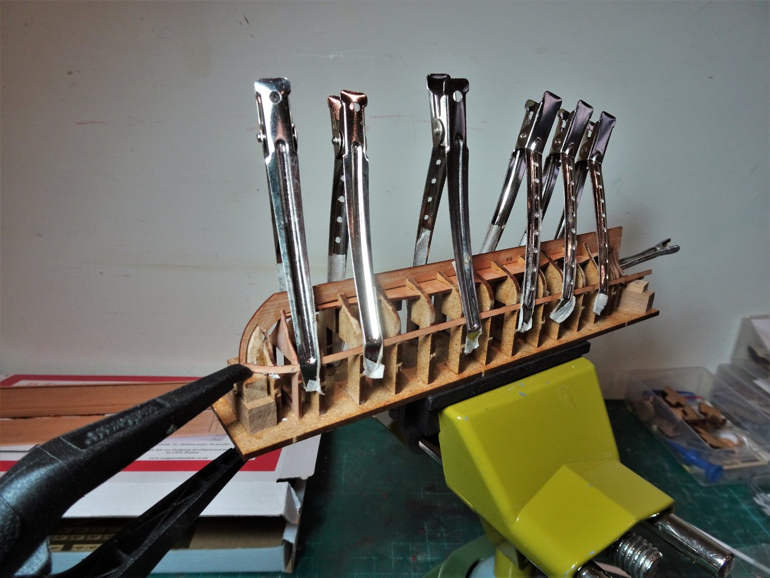
It is a slow business planking at this scale.
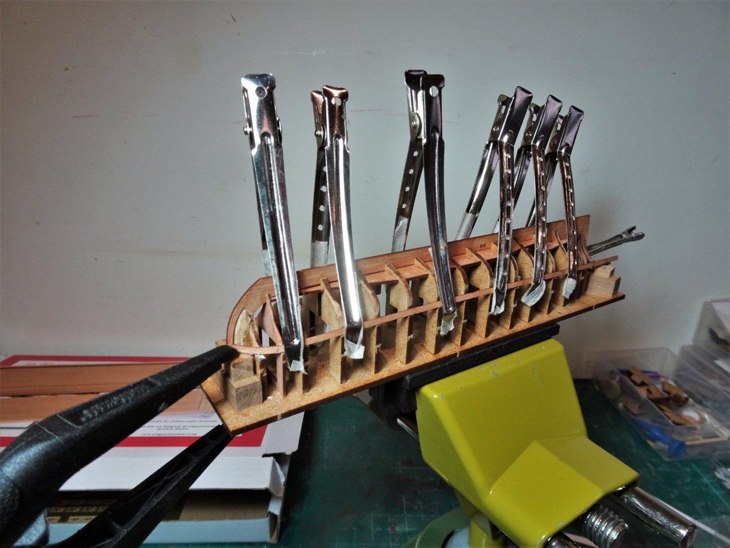
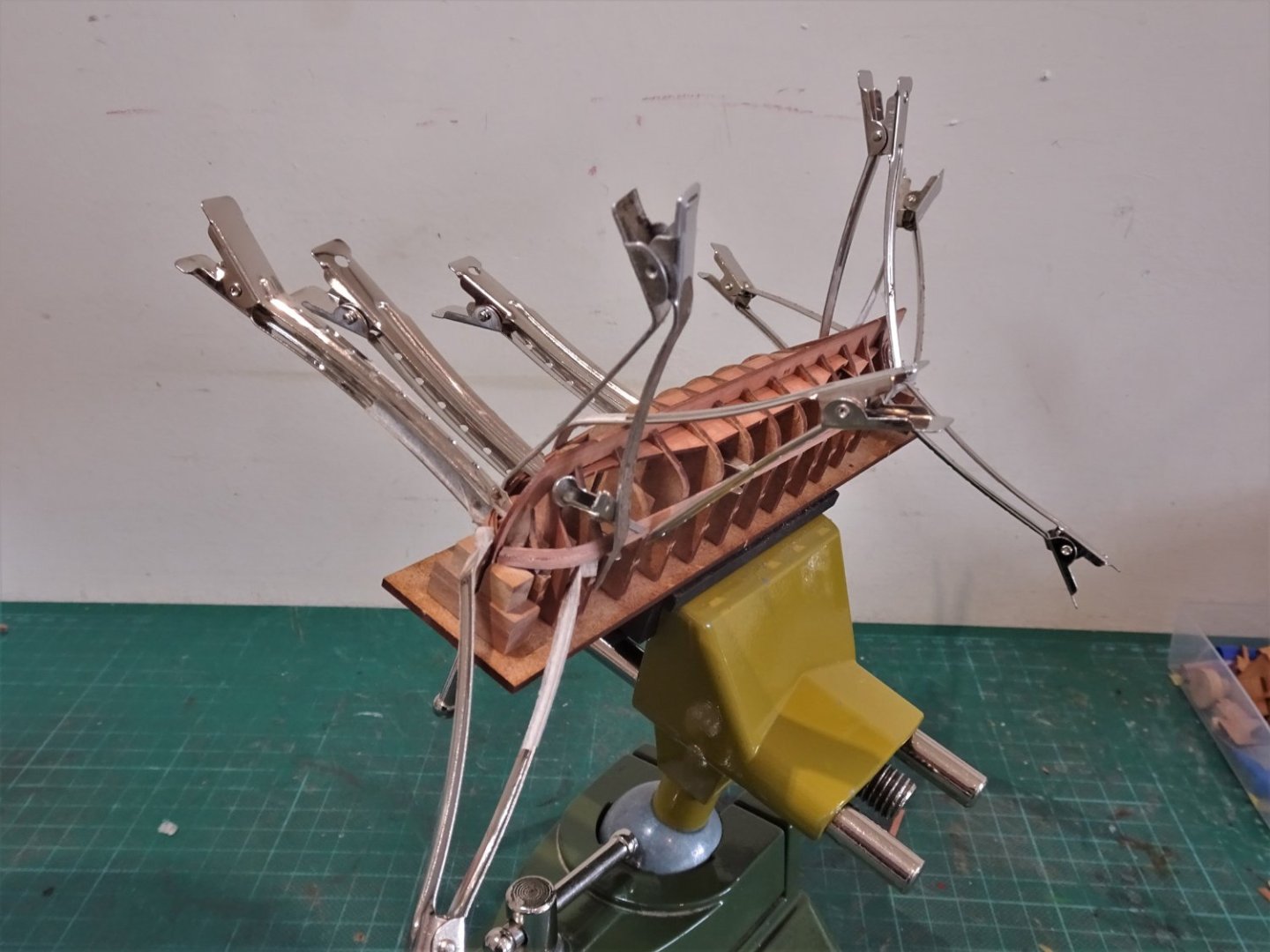
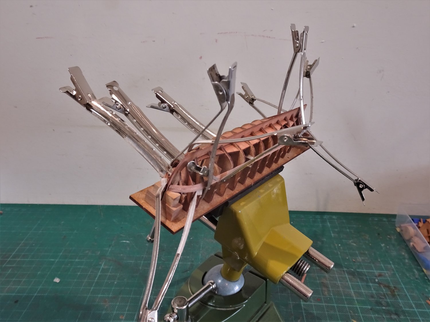
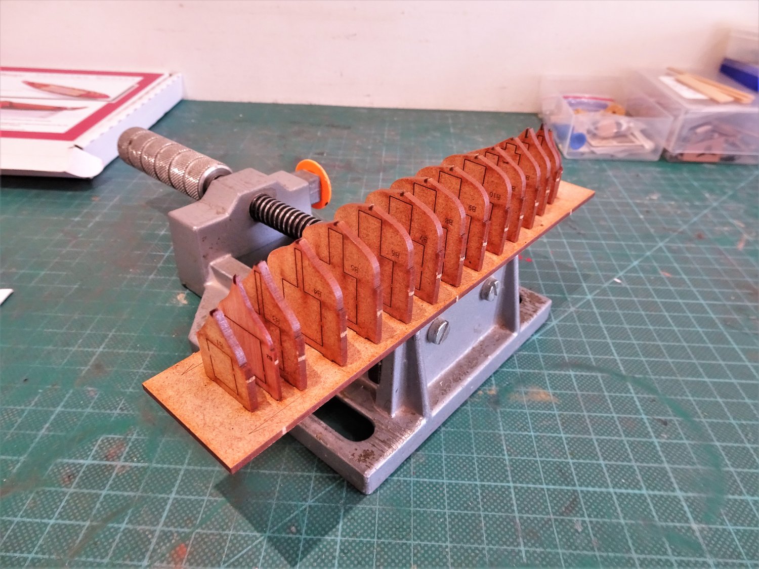
Each strake has to be tapered, bevelled, wetted, edge bent, wet fitted, clamped in place, and blasted with the hairdryer, and left until formed.
9259
These sectioning clips are ideal for the purpose, applying the right degree of pressure on this fairly delicate hull.
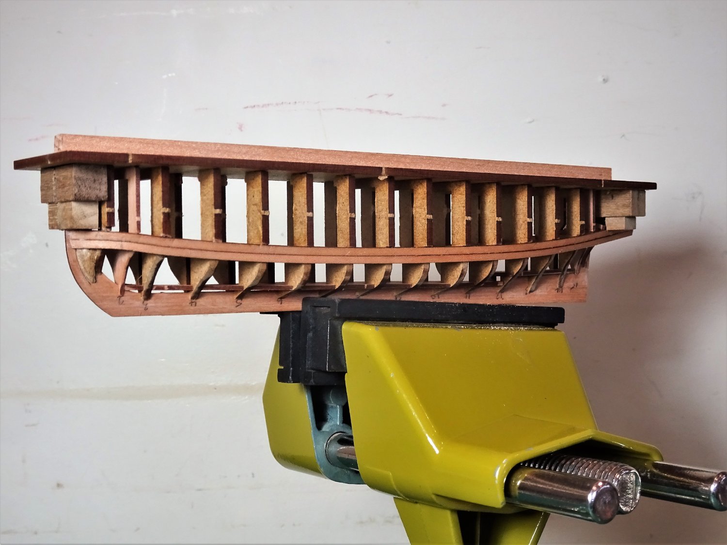
After what feels like half a lifetime the planking nears completion.
.thumb.JPG.9001b7e5b1f1ea9ad0e4551a22d54e39.JPG)
9307(2)
.thumb.JPG.754331d91a30f2e080486bb8d5f5c499.JPG)
9309(2)

9310
9308

9319
A week’s planking leaves two strakes left to finish.
These will be the garboard plank and a spiled plank that will sit on the bottom of the hull out of sight.

9314

9318
I have not found planking an easy job on this project and it looks pretty rough at this stage, a lot of fettlin’ to do to get an acceptable finish.
Hopefully it will look a lot better in the next post.
B.E.
12/11//2020
-
A fascinating process Ron, I will follow with great interest.
B.E.
- mtaylor, Beef Wellington and Jack12477
-
3
-
A fine crew indeed, nicely done Ron.
I am surprised that Captain W has arrived to take command wearing britches that look like he found them in the bilges, what is his servant thinking of.
The officer class must maintain standards.
B.E.
- hollowneck, mtaylor, HardeeHarHar and 3 others
-
5
-
 1
1
-
Thanks for looking in Håkan, I suspect the age comment has something to do with liability to guard against claims that my little rug rat has just eaten your barge - you never said it wasn't edible. 😉
Even so, 36 months is a pretty low age bar, but then I wouldn't be surprised to learn that Chris was knocking stuff like this out aged four.
A more appropriate warning would be; getting involved with this kit may seriously damage your mental stability at any age.
I jest of course. 😬
B.E.
- Wintergreen, James G, hollowneck and 2 others
-
2
-
3
-
Fun of course is a relative term; I'm missing a pathfinder build log from you James, where I can sit and stare at the process, does not Indy have a barge?
I think my Flying Transom has shifted somewhat since I fitted it, but as long as the arms don't break the panel can be re-jigged.
The more I look at your Indy build, the more my resolve not to succumb to it weakens - repeat I cannot do another large-scale build, I have not the room for another large-scale build......
B.E.
- mtaylor, hollowneck, gjdale and 1 other
-
4
-
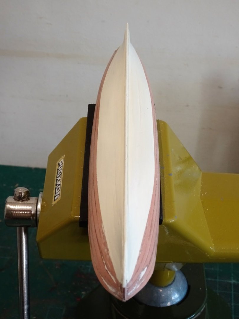
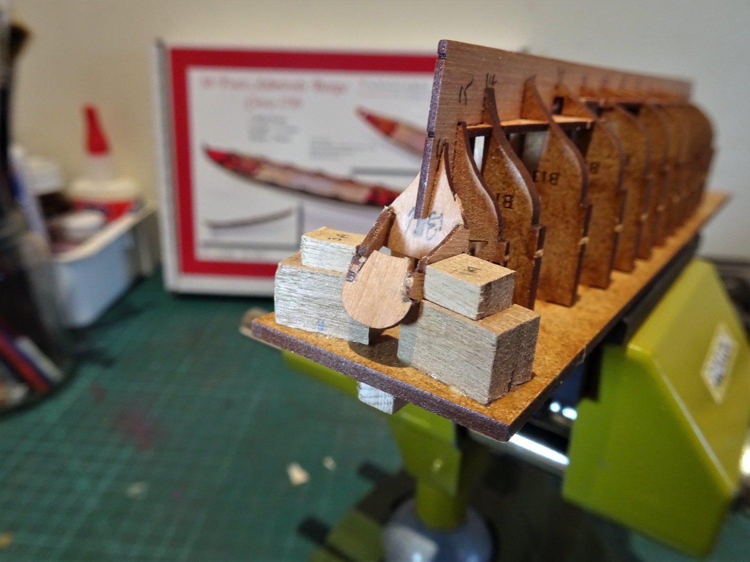
Post Three
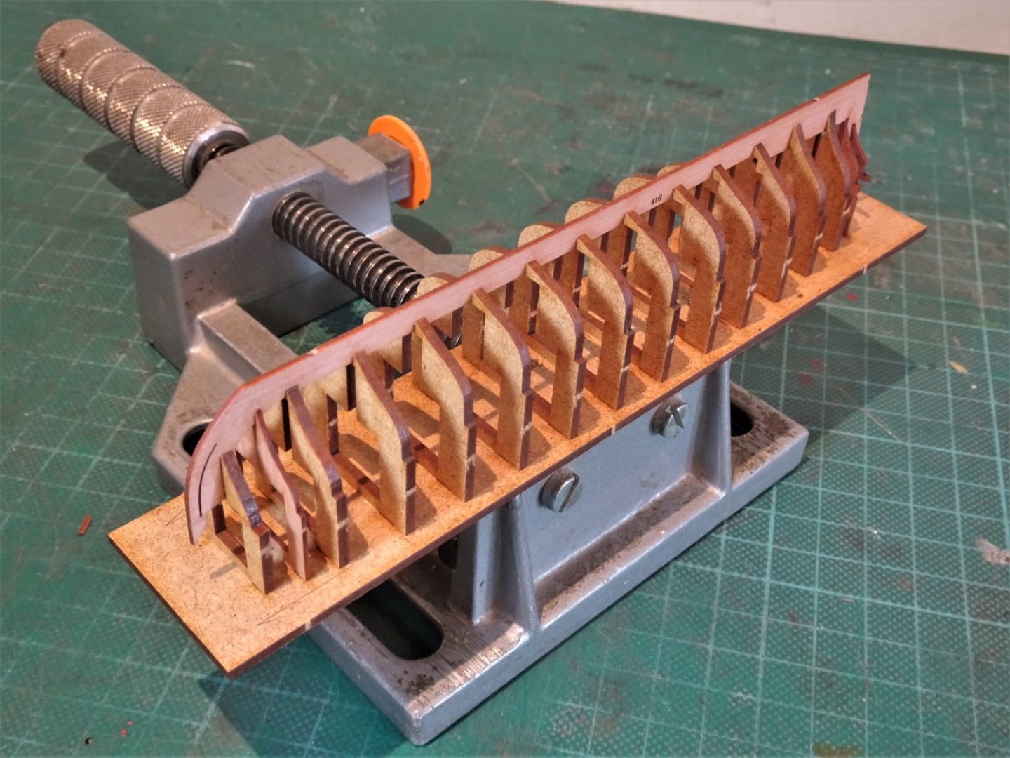
Bevelled bow patterns have been attached.
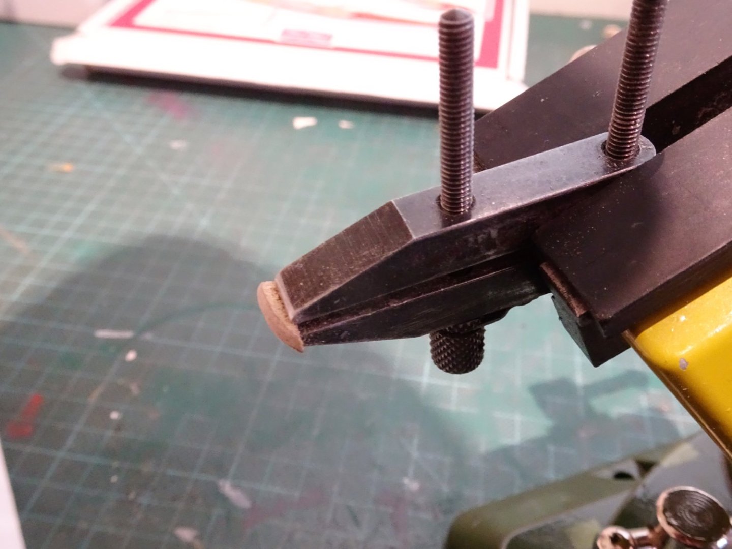
9202
These are tricky to hold for bevelling, I use my toolmakers clamp which works very well.
9211
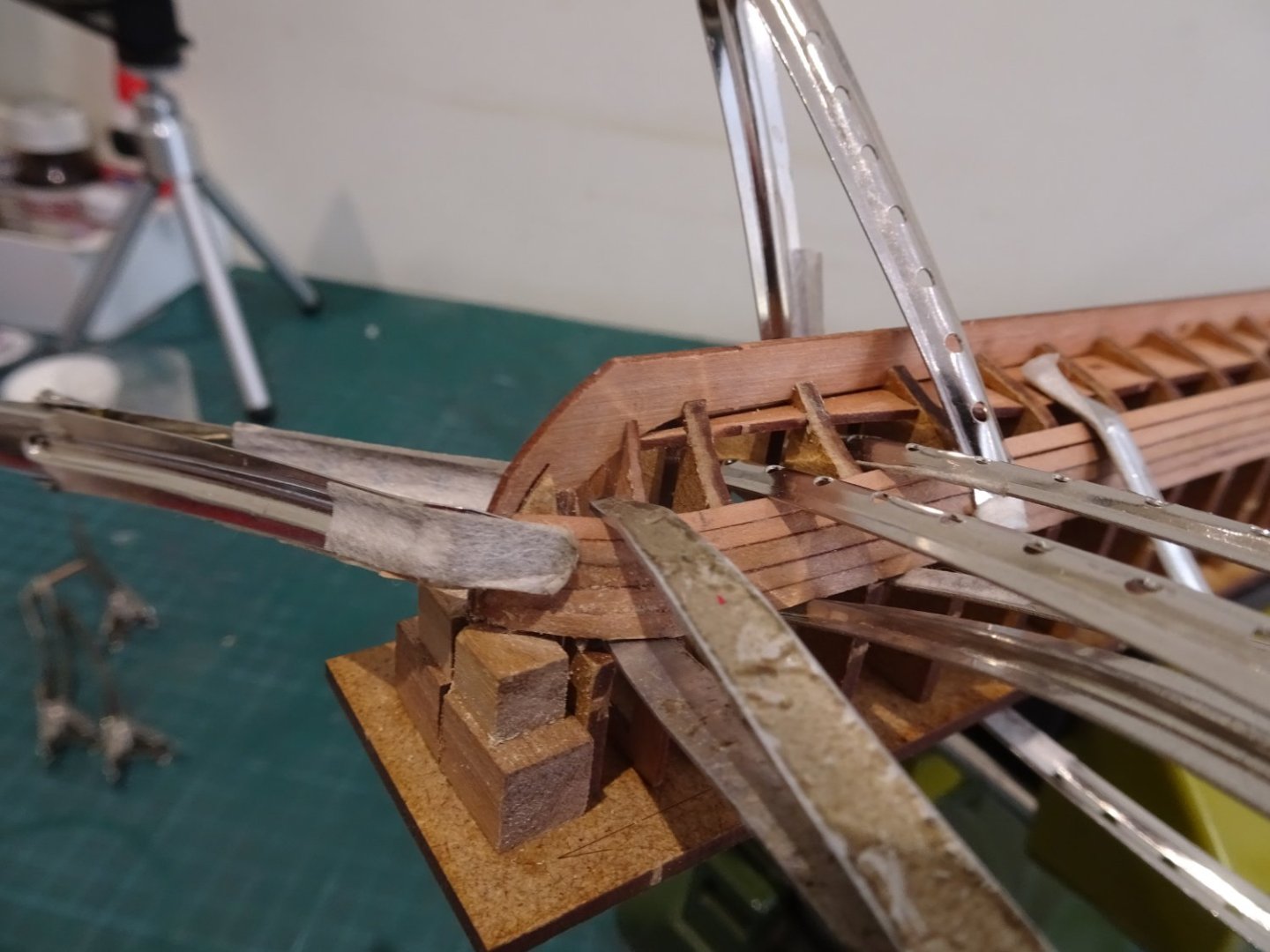
Before the fairing is started, I add support blocks to protect the Flying Transom; at this stage it is very vulnerable.
For the fairing I am using 320 grade paper attached to various width sanding sticks. Being mdf the fairing is quickly done, the four bulkheads from the bow and stern are the ones involved.
As with all this range of boats the first plank rests on the shoulder of the bulkheads to give the correct line and sheer.
More easily said than done at the bow in relation to the Barge.
The bows of Barges were fairly bluff so there is a tight turn from the stem around the first two bulkheads.

9213
Coupled with this there is a sharp drop in shoulder levels from Bulkhead 1 to bulkhead 3 requiring lateral bending also of a greater curve than is easily achieved.
The instructions don’t mention any need for lateral bending on the first strake, only referring to tapering from the second strake plank.
To secure the planks spots of ca are used from the stem to the third bulkhead, and pva thereafter.
9217
After a fair bit of fiddling around including breaking the end off the first plank, I am relieved they are finally fitted.
I derived a small amusement that the box contained the statement Not suitable for children under 36 months
Double that, call it years, and then some, and I still wonder if it’s suitable.😉
I don’t think this is going to be an easy planking job.
Close examination of the prototype pics indicate that stealers have been employed at the bow and what look like broader planks for some of the strakes towards the keel.
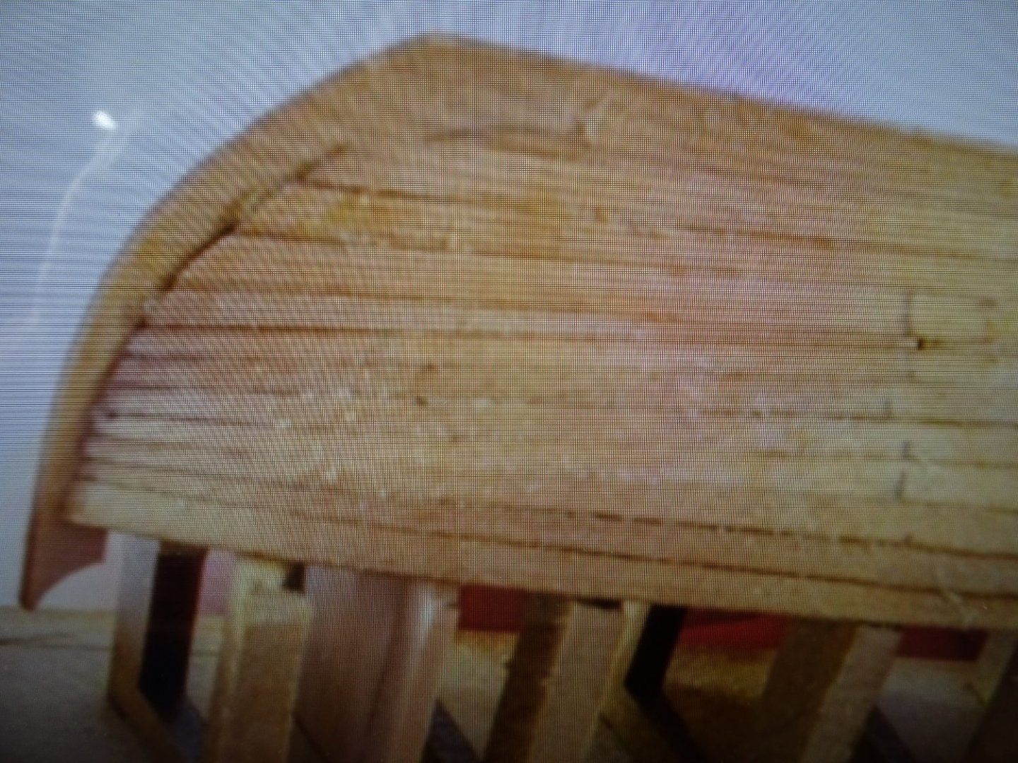
Prototype close-up – the pdf photos are a little small for detail, but it can be seen how James achieved the result.
This will get the job done and as the hull is intended to be painted such simplifications are perhaps less relevant.
However, I will try to attempt a more conventional arrangement.
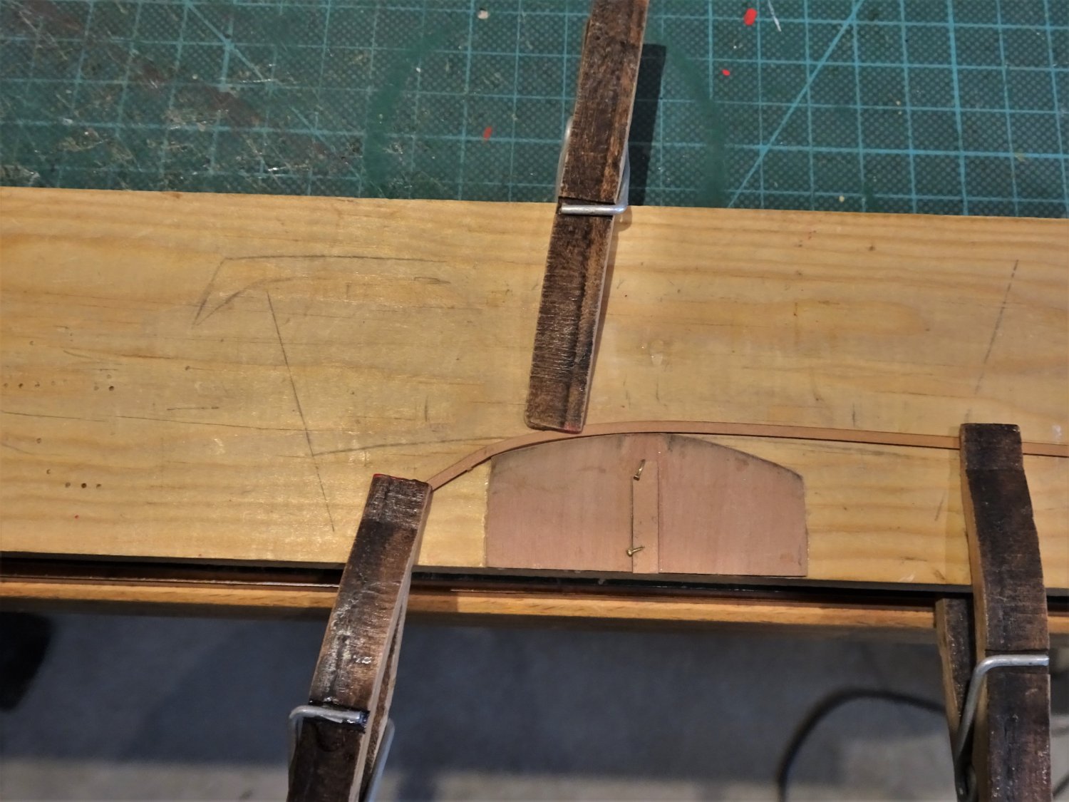
From the second plank tapering is indicated.
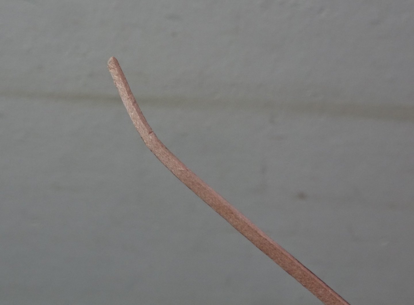
9222
I opted to leave the plank full, but edge bend it to follow the first.
On the question of tapering, the planks used are 2mm x 0.8mm which makes it difficult to adopt the usual tapering method of cutting the line using rule and scalpel.
Tapering is done by means of scraping and careful sanding on a flat board to finish. Any tapering should not exceed half the plank width ie 1mm.
Fortunately, I do have some 0.8mm Pearwood Strips in varying widths, which will give more options.
9228
It is more difficult edge bending the kit lengths as it has to be done at the end of the strip which is obviously less flexible.
Having soaked the planks, the bend was induced by hand, fitted to the hull, held in place as above, and blasted with the hairdryer.
.thumb.JPG.d7123ee3b3fc1c1e49c0c3c6201c3db1.JPG)
9236(2)
Spots of ca are used to secure at the bow, with pva along the edge joints, and sparingly on the bulkheads, which will eventually be removed.

9234
.thumb.JPG.0a612c6738a32fcc76db36ea00579c1c.JPG)
9237(2)
The sheer of the hull can be seen in these shots.
.thumb.JPG.1d915ee59da35a91ccde2eb051cf45e2.JPG)
9241(2)
Note the blocks glued to the base board to protect the delicate stem.
Hours of unremitting fun now to be had completing the hull planking.🙄
B.E.
06/11/2022
-
Cheers Guys,
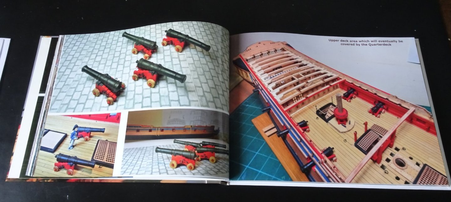
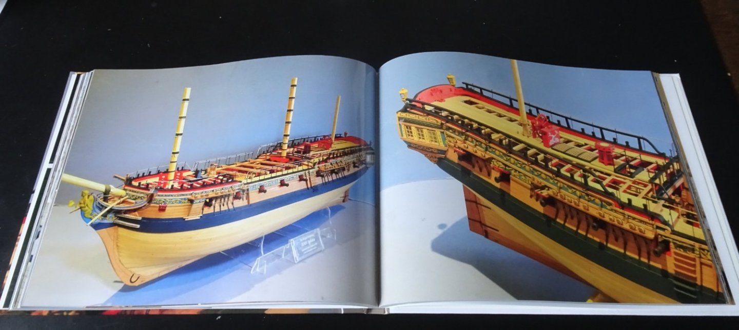
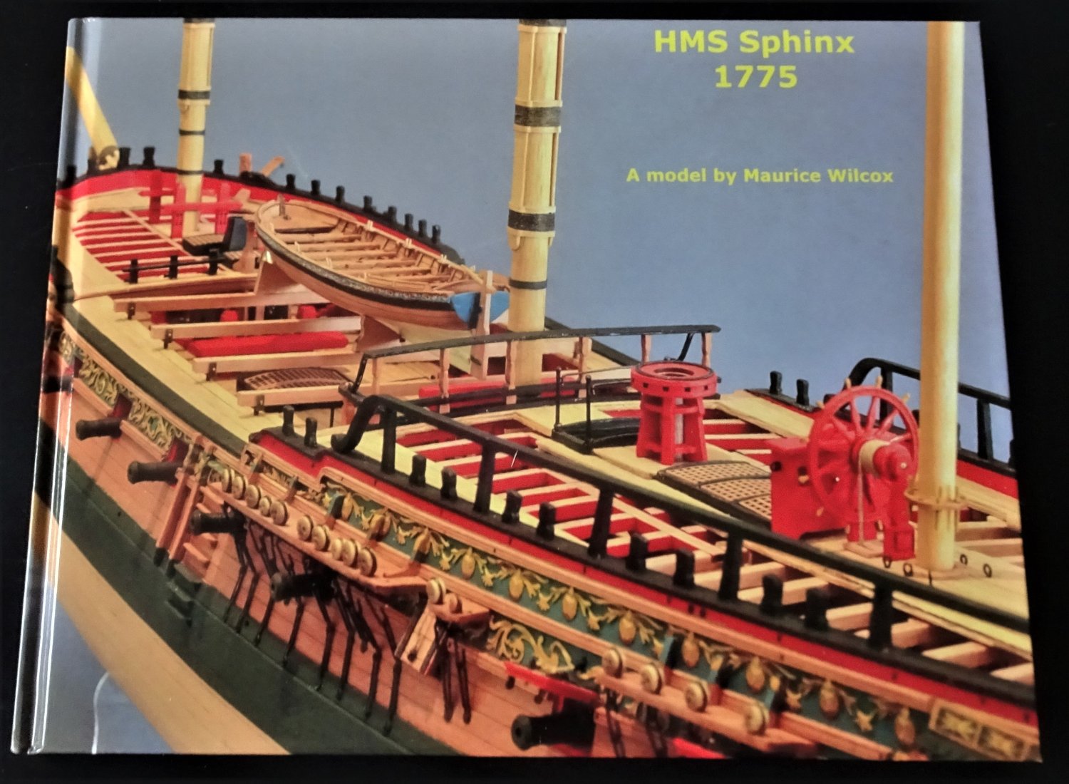
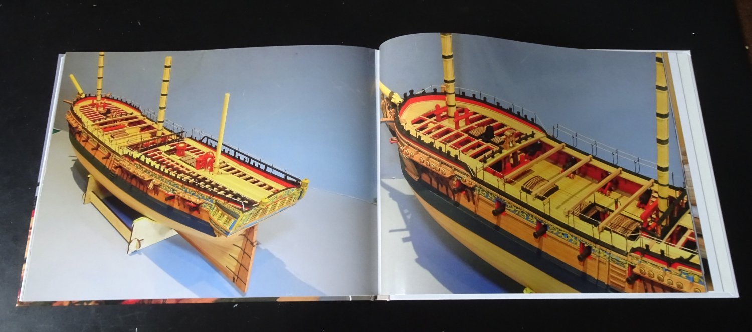
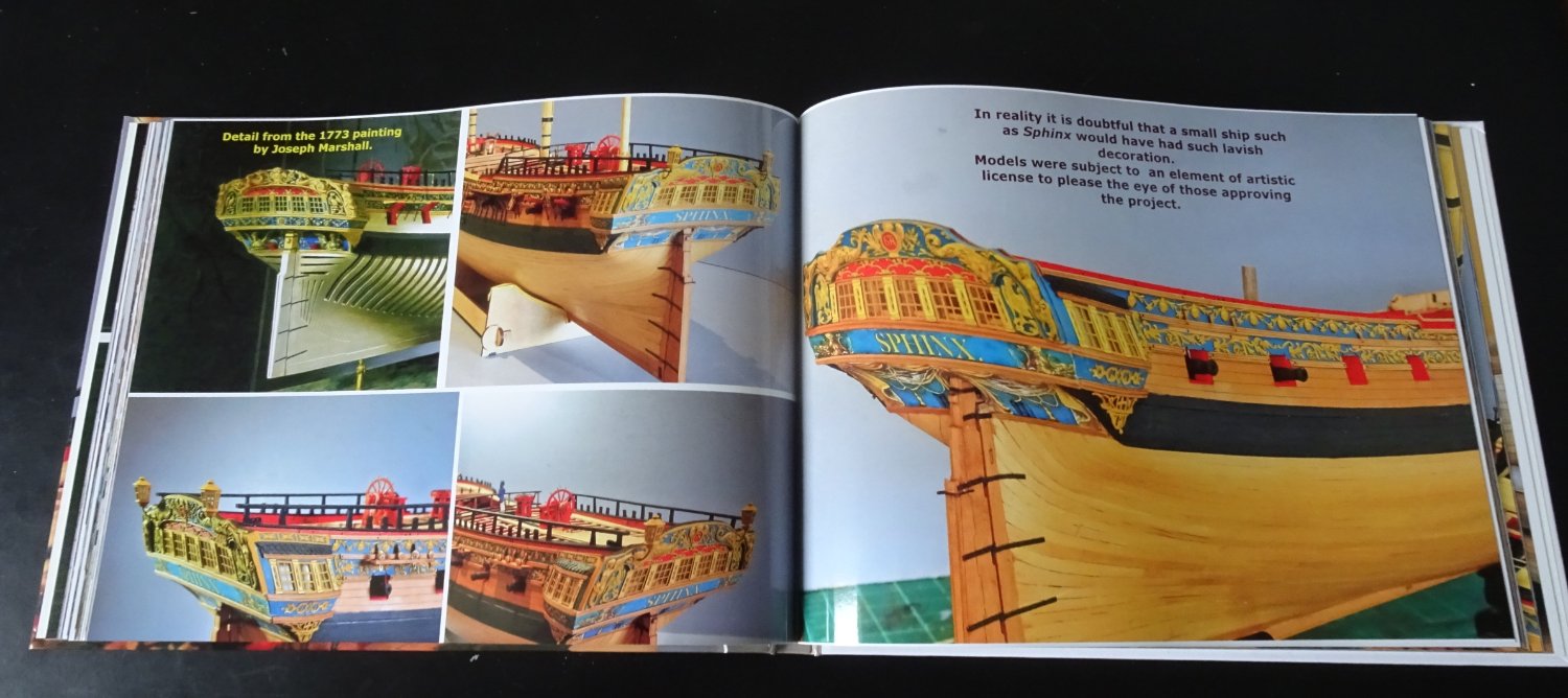
As it happens in the past week, I have received my printed pictorial build album.
I have done one of these for all my builds, it is a shame not to use all those build photos and record those internal details lost from view.
A few pages to give a flavour.

9094
9095
9096

9097

9098
.thumb.JPG.3dde3f42fcf7baa29e2f061f0b22ea7c.JPG)
8926(3)
Once again, thanks for your support, much appreciated.
B.E.
05/11/2022
-
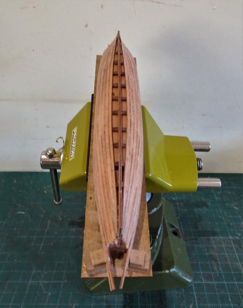
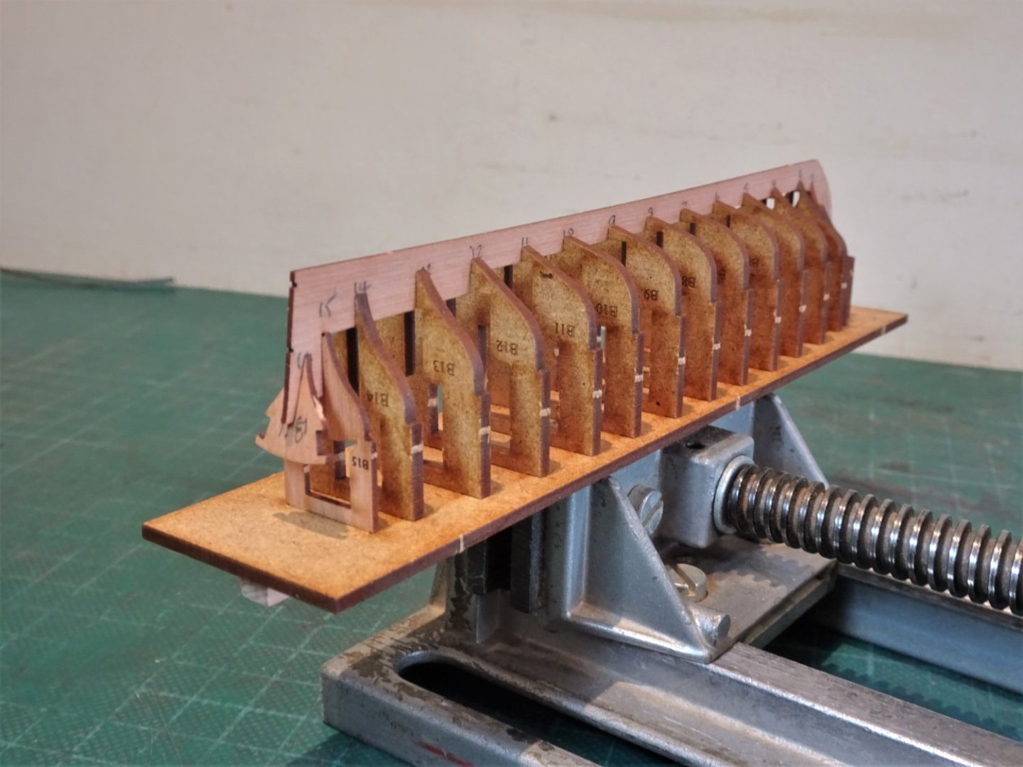
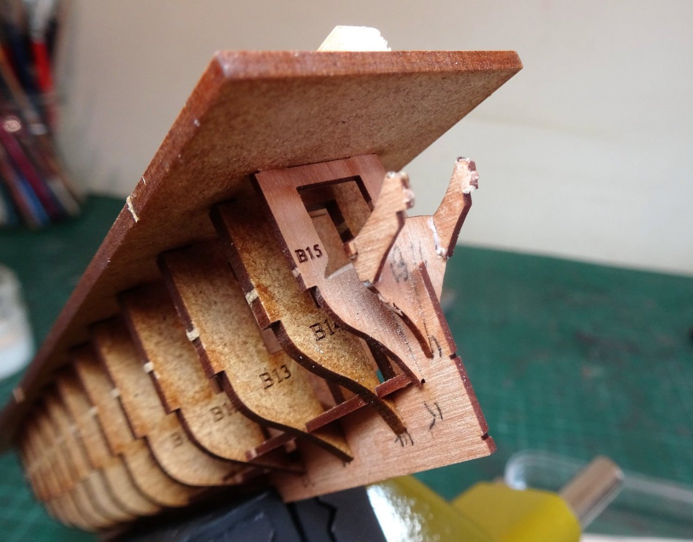
Post Two
Not the most exciting part of a build, but I don’t think James has covered the Barge in his build logs, so I’ll run thro’ the initial stage.
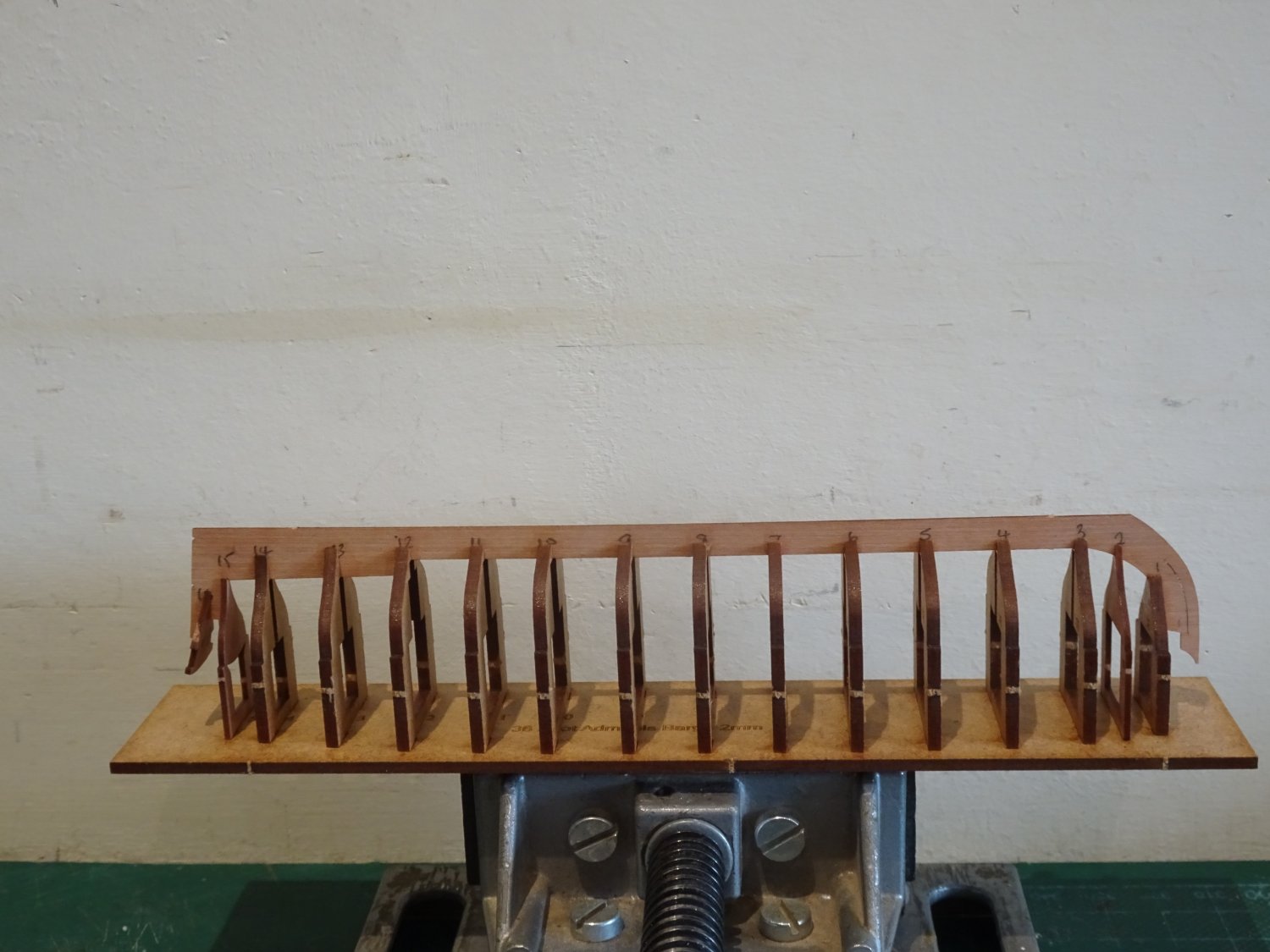
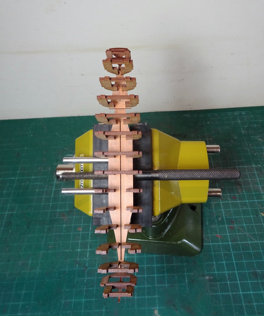
The bulkheads fit snugly into the building board to the underside of which a grip is glued to secure in a vice.

9165
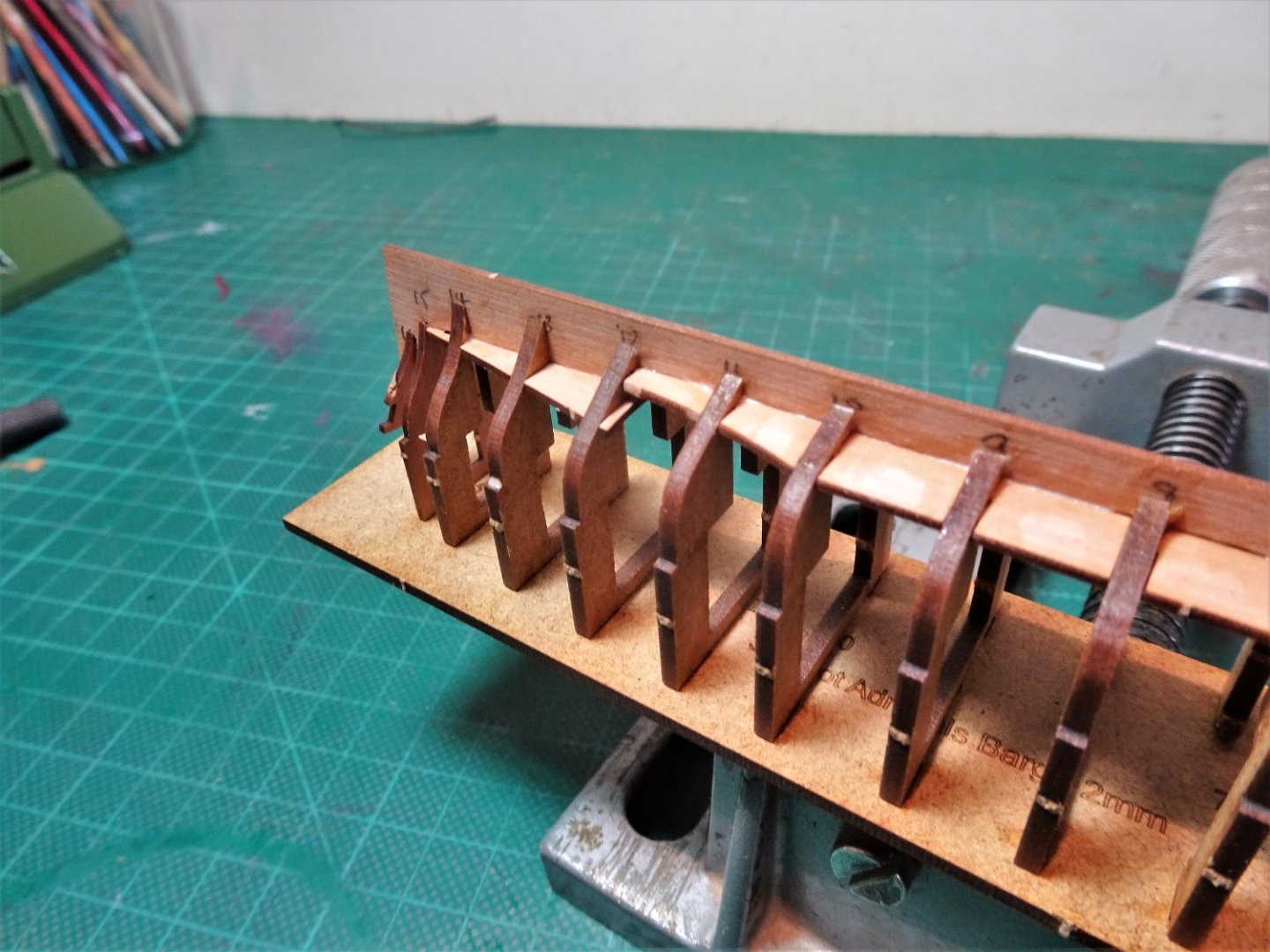
In short order the next stage is to fit the delicate Pearwood keel.
This is a soft hands procedure and care must be taken not to force the keel slots into the bulkhead slots which are very fine particularly those at the bow and stern.
I tested each keel slot against its bulkhead partner before attempting the keel fit.
 9170
9170
9167
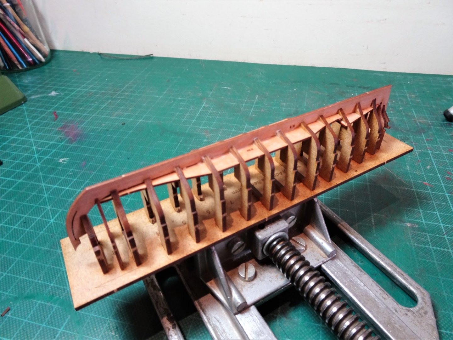
The keel is eased into position, and I ensure it sits fully down on the bulkheads.

9173
The keel is also checked for true. Once satisfied diluted pva was run into the joints.
9186
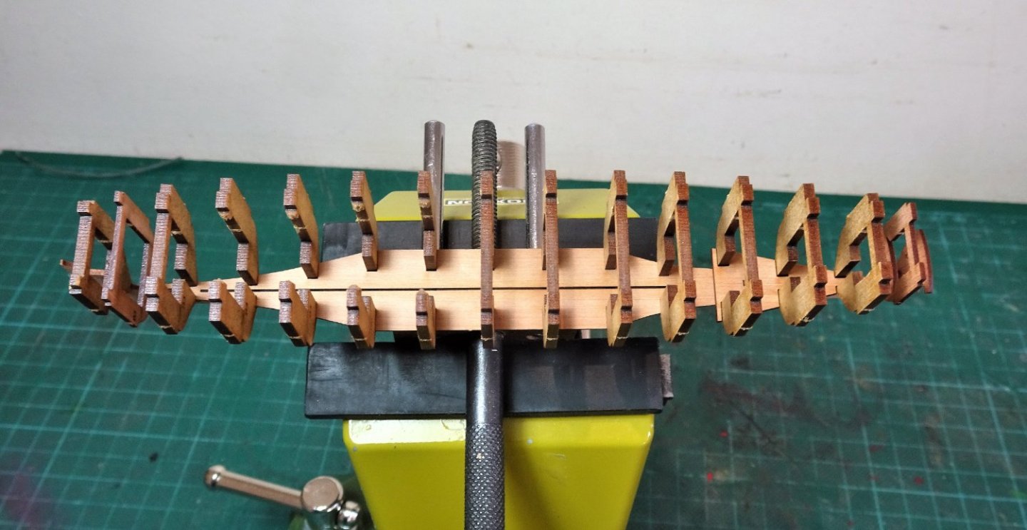
Unlike other boats in the range the barge has a sub-deck. To fit this four of the bulkhead bridges have to be removed to allow access.

9177
9189
9192
One of the advantages of the sub-deck is that it should help to counter twist in the bulkheads once the fairing begins.
9193
The arms of the Flying Transom are glued into place.

9199
Fitting the Flying Transom is a tricky business, I opted to glue the arms to the fixed transom first, and then slotted the Flying transom between before the pva hardened off.
The hull is now set aside for the glue to set.
B.E.
04/11/2022
- tkay11, Ryland Craze, yvesvidal and 11 others
-
14
-
-
-
-
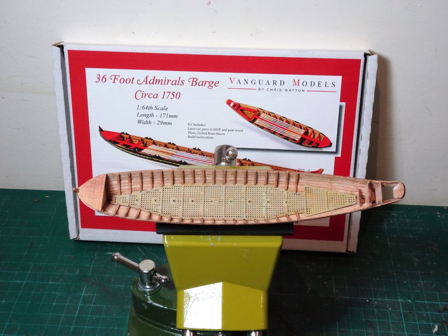
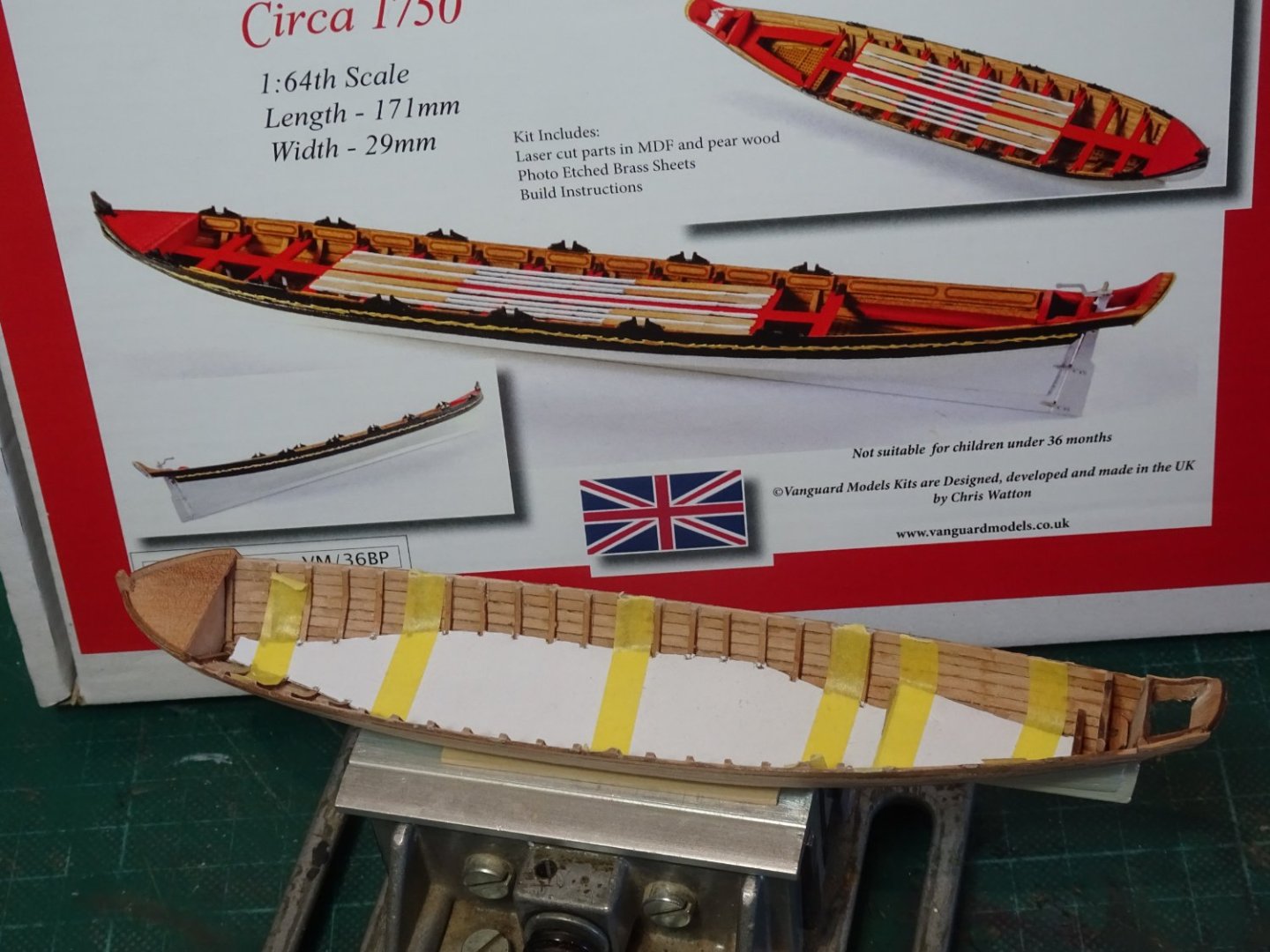
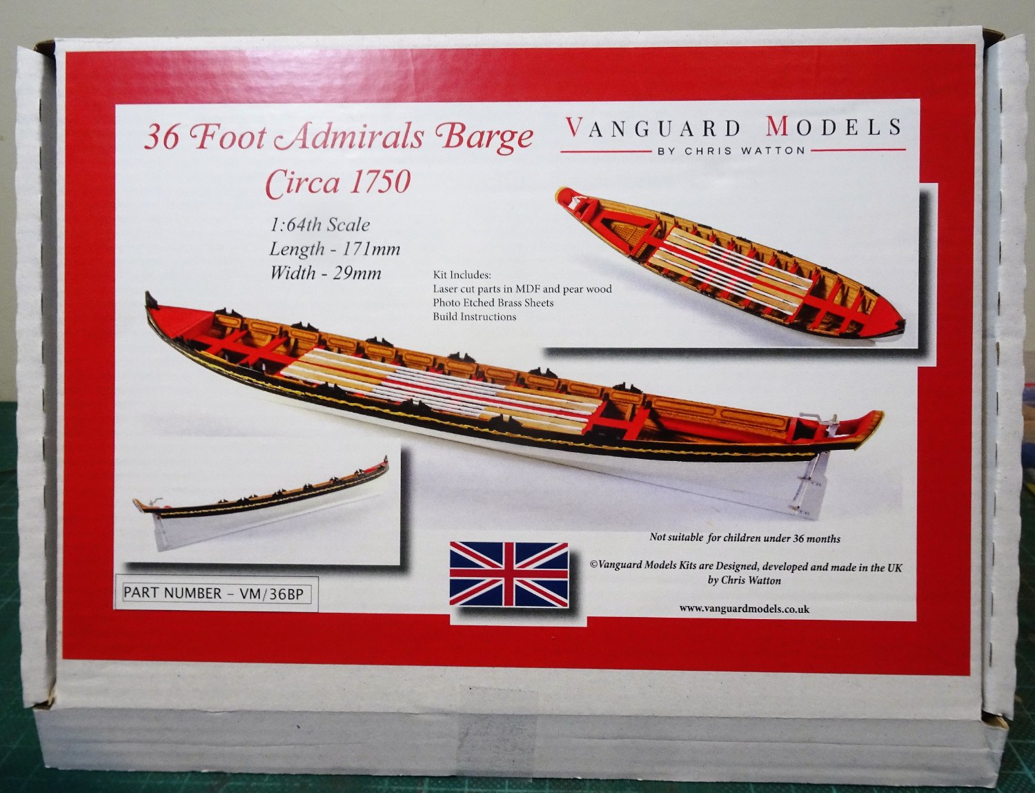
I am still not ready to move onto a larger project, but I have had for a while an example of Vanguard Models 36’ Admirals Barge circa 1750.
I have included this build in the 1751-1800 section as it generally reflects the style from the middle to late 18th century.

09158
At £48 this is the most expensive of the current boat range, an added incentive not to cock it up.
The model has a length of 165mm - 6½” in old money – still pretty small to fit in the extra detail applicable to an Admiral’s Barge.
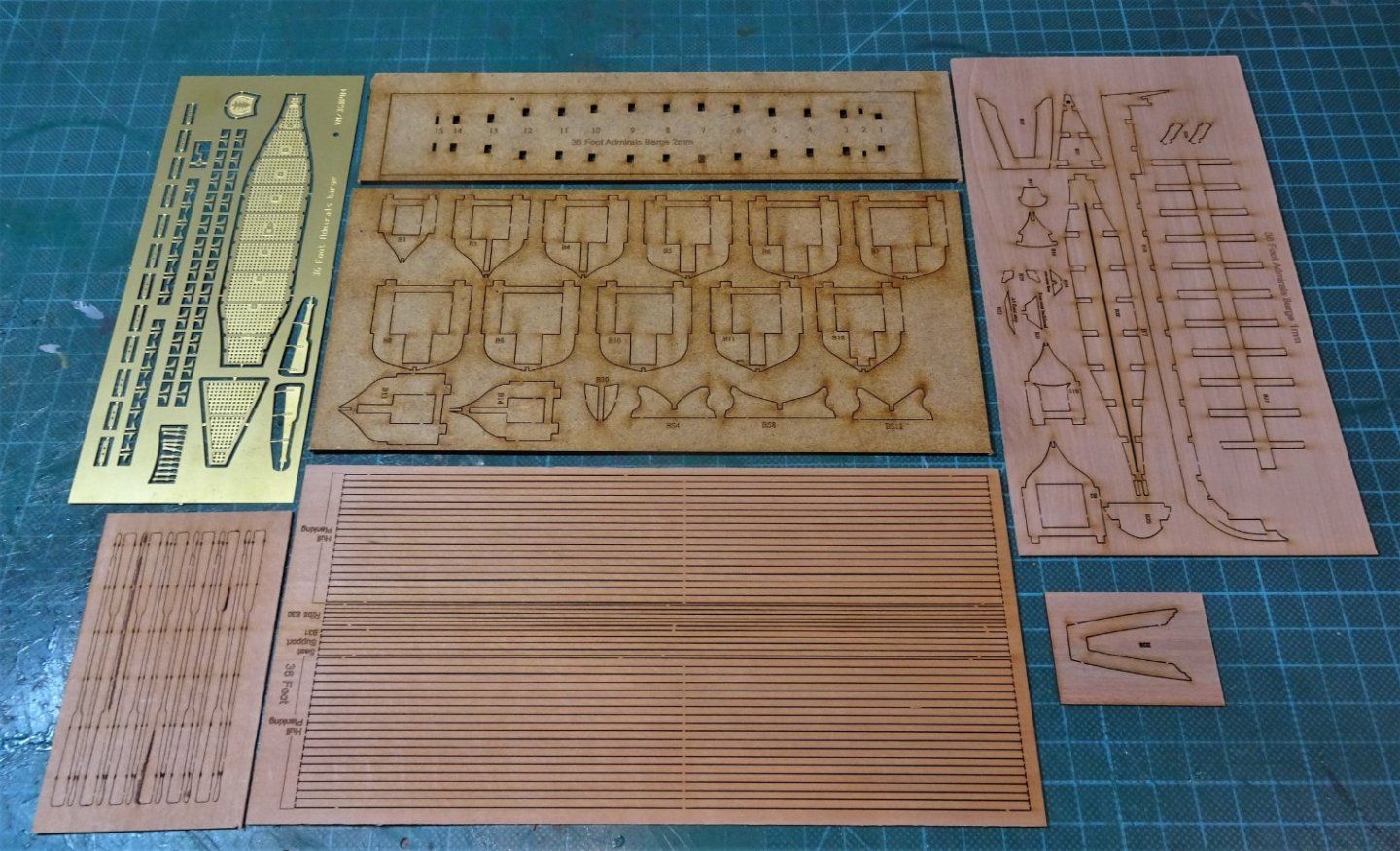
09160
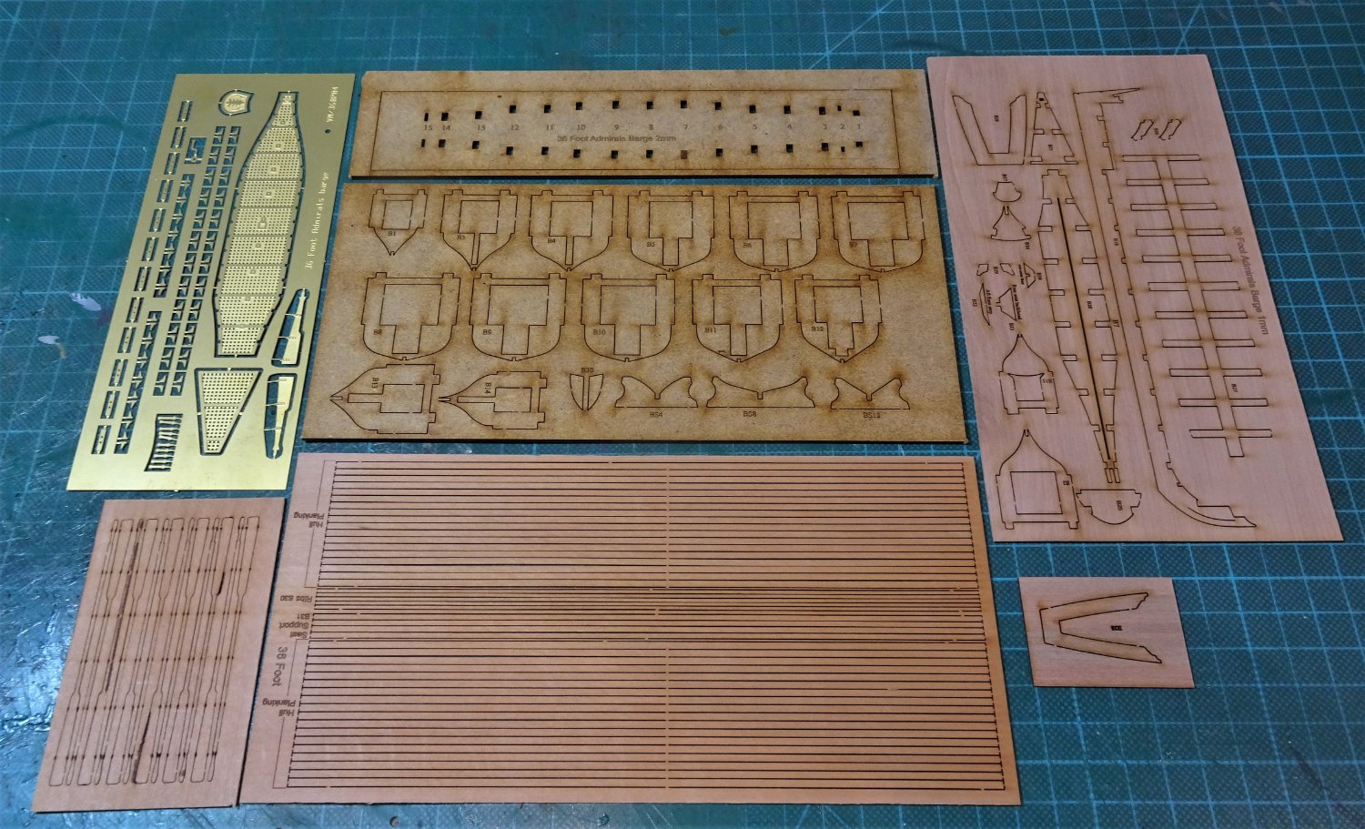
The kit follows the build method common to this Vanguard range, plank over inverted bulkheads using Pearwood planks.
09162
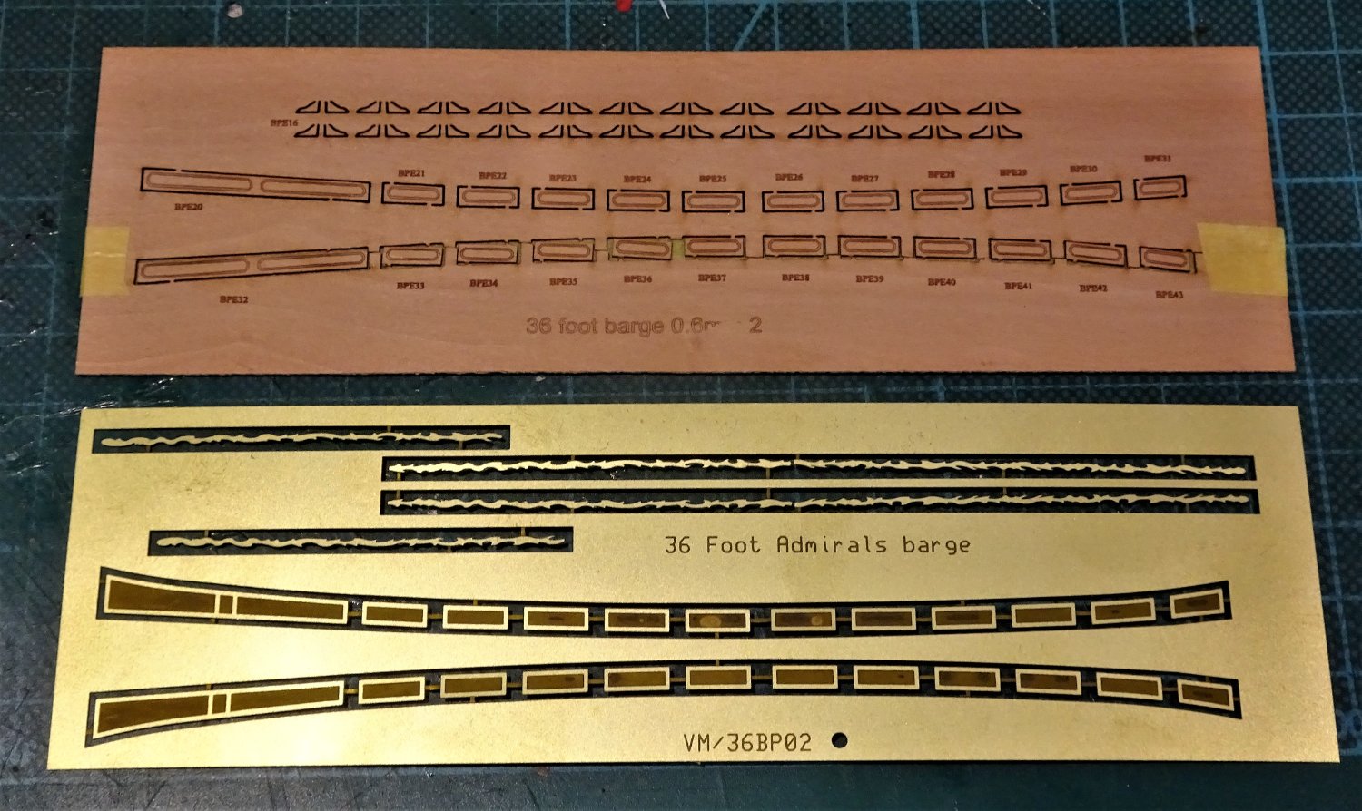
Brass etch is provided for the footwaling and decoration, but the provided brass etch panelling has been replaced with Pearwood detailing also included in the kit.
I do have a fondness for this type of boat, having built three Pinnaces and Queen Anne’s Barge, and this bijou version presents some interesting challenges.
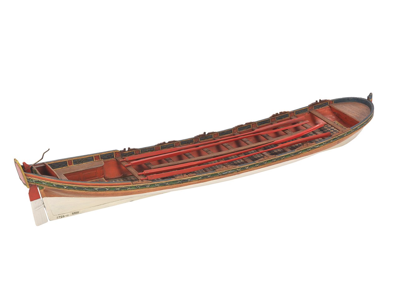
It is fortunate that there are several contemporary models of Barges in the NMM at 1:24 scale from which to draw detail.
One thing that catches my eye is that the kit is set up for double banked rowing - thole pins both sides for each thwart, and two rowers per thwart.
The contemporary models of this period invariably show Barges set up for single banking - one rower to each thwart seated alternatively port and starboard, with a longer oar shipped over the opposite side of the boat to the rower.
0929
A mock-up on my Pinnace build shows the arrangement for single banked rowing.
This is all a fair way ahead in the build and need not concern me yet.
Basics first.
B.E.
03/11/2022
-
Thank you kindly Druxey, I have enjoyed this little infill project and I would love to oblige but the Cook's assistants have doused the fire, raked the grate, and cleared the ashes.
I've now moved back to the boatyard for another testy little project.
Regards,
B.E.
-


.JPG.beb8164ecd52d9c21f2e74f3640a5307.JPG)
.JPG.32d6c97d997d13d00cca212353ce7476.JPG)

.JPG.6232ce18e5aa727598d031c4ae8a83a3.JPG)
.JPG.2aaafa6300926716638e53657d599d25.JPG)
.JPG.88c8ce77d1ef37244df76f585f385de5.JPG)
.JPG.9a0766dda68cfa9f67fe38fd874a047f.JPG)


.JPG.fca0d89c9db81ef5e50c6adcb4bfdb5d.JPG)
.JPG.c10705cac274938be3ebb96c0cecccd3.JPG)
.JPG.ca4de23d35e9c14b37edd3531161679c.JPG)
.JPG.8ea32f09ef7350be3397ed73132479e2.JPG)
.JPG.57aae3b0e066ff4554696b44416a2f71.JPG)
.JPG.3e1b31ef8fb708148dca0a02fee655be.JPG)

.JPG.7ed6384a04a8c05e5329bf6576344405.JPG)
.JPG.277cfc00c51efde3668f5ec382b0ba86.JPG)


.JPG.3279f973485cbb7a50be78616a4d92f8.JPG)
.JPG.eee0c9c9445356b4365620b8f2aa03c3.JPG)
.JPG.e96f7c888e3fb4a12ffebaf9630824bc.JPG)


.JPG.3dd8d1a5ce6f2d2a7837d31c2350df6d.JPG)


36 Foot Admirals Barge by Blue Ensign – FINISHED - Vanguard Models – 1:64 scale
in - Kit build logs for subjects built from 1751 - 1800
Posted
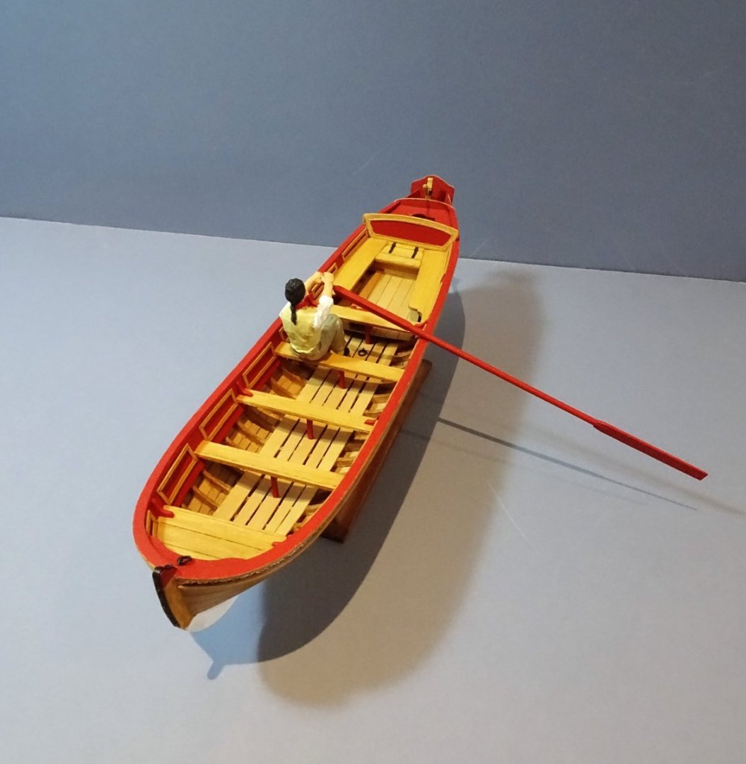
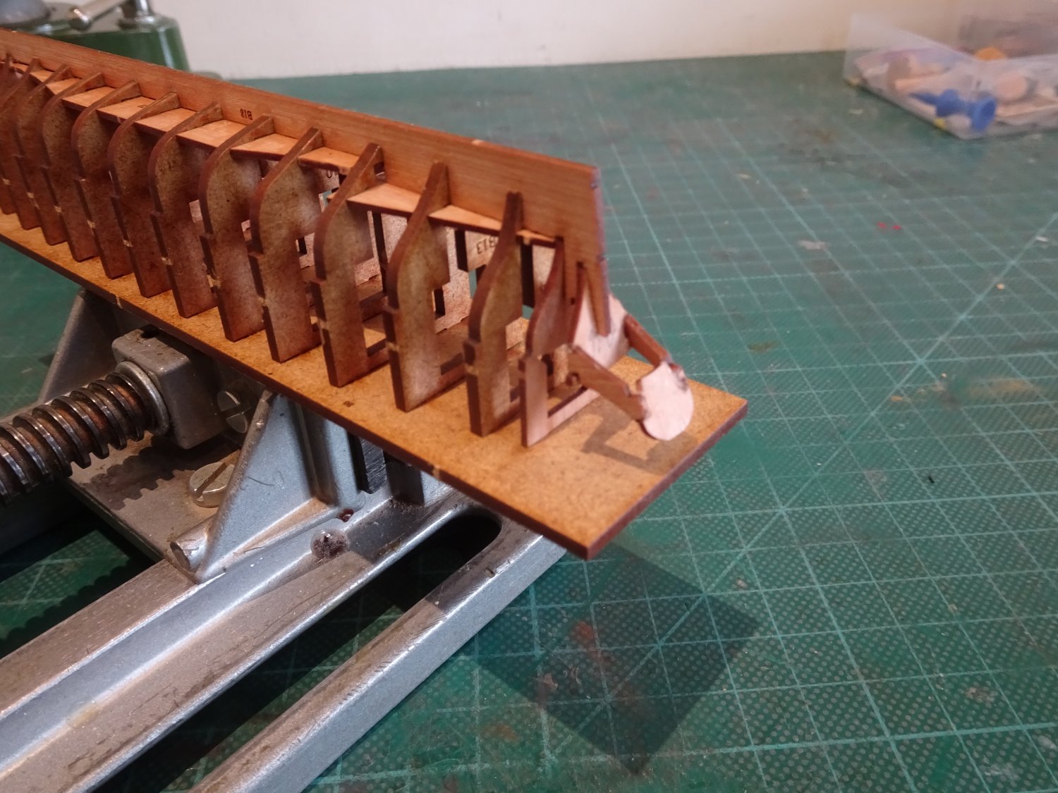
Post Ten
Internal fittings are now removed for test fitting.
The thwarts are an integrated unit combining the central Longitudinal plank. This is typical of barges of this period.
9440
The stern benches are also a single unit that look to require only minimal adjustment to fit.
Before they are fitted the seat stanchions that run down the centre of the footwaling are required to be fitted.
Section 38 of the blurb refers to the fitting but does not mention that the stanchions are of brass etch.
9438
They are numbered sequentially on the blurb and a careful check of the etch shows that the ten stanchions are position specific, fore, and aft to accommodate the sheer.
They are not however, numbered as per Section 38 of the blurb.
The way the kit is set up the stanchions dictate the height of the thwarts, and the hull ribs will need reducing in height where they impact on the thwart ends.
I decided to use the etch supports partly because I felt they gave the best chance of getting the thwart height correct.
9467
9465
The biro gives the relative size of the barge.
9470
I was still keen to check that the thwart height was correct.
9469
Unlike the usual practice of risers along the internal hull to support the thwarts, this kit relies on the central columns and the ribs cut to suit for support.
9468
With the scale figures in place, I am pleased to see that the height is good. It is also clear why barges of this era were rowed single banked.
My use of ‘test’ thwarts has given me the line for the risers, and I don’t really understand why they haven’t been employed on this kit.
48Bb(2)
Once the thwarts and benches are in place small wooden block panels are fitted between the thwarts along hull.
This is a simplification of the proper arrangement, perhaps understandable given the scale, but it does look a tad unconvincing to my eye.
The inner hull should be lined over the ribs and decorative mouldings applied.
I have an idea of how to do this from my Model Shipways Pinnace build, but that was at 1:24 scale.
Before I admit abject defeat, I will have a play around and see what can be done.
B.E.
20/11/2022