HOLIDAY DONATION DRIVE - SUPPORT MSW - DO YOUR PART TO KEEP THIS GREAT FORUM GOING! (Only 36 donations so far out of 49,000 members - C'mon guys!)
×


Chuck
-
Posts
9,660 -
Joined
-
Last visited
Content Type
Profiles
Forums
Gallery
Events
Everything posted by Chuck
-
 Mark…your model is looking spectacular. Its always a great source of inspiration. The molding will look great once added and I look forward to seeing it. That ship’s hull has such a beautiful shape….its hard to stop admiring it.
 -
I have no idea why that is happening to you. But the progress looks really good. I like what you are doing with the model. Its nice to see you forging ahead.
- 105 replies
-
- 1
-

-
- winchelsea
- Syren Ship Model Company
- (and 1 more)
-
That looks fantastic….such a nice model. Just found your log….better late than never.
-
John…. any luck getting this model back on the workbench? I was just checking out your log again for some i sight on a possible project…would love to see this wonderful model start taking shape again.
-
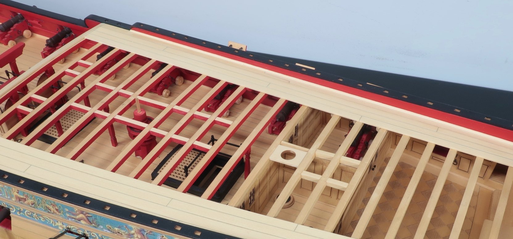
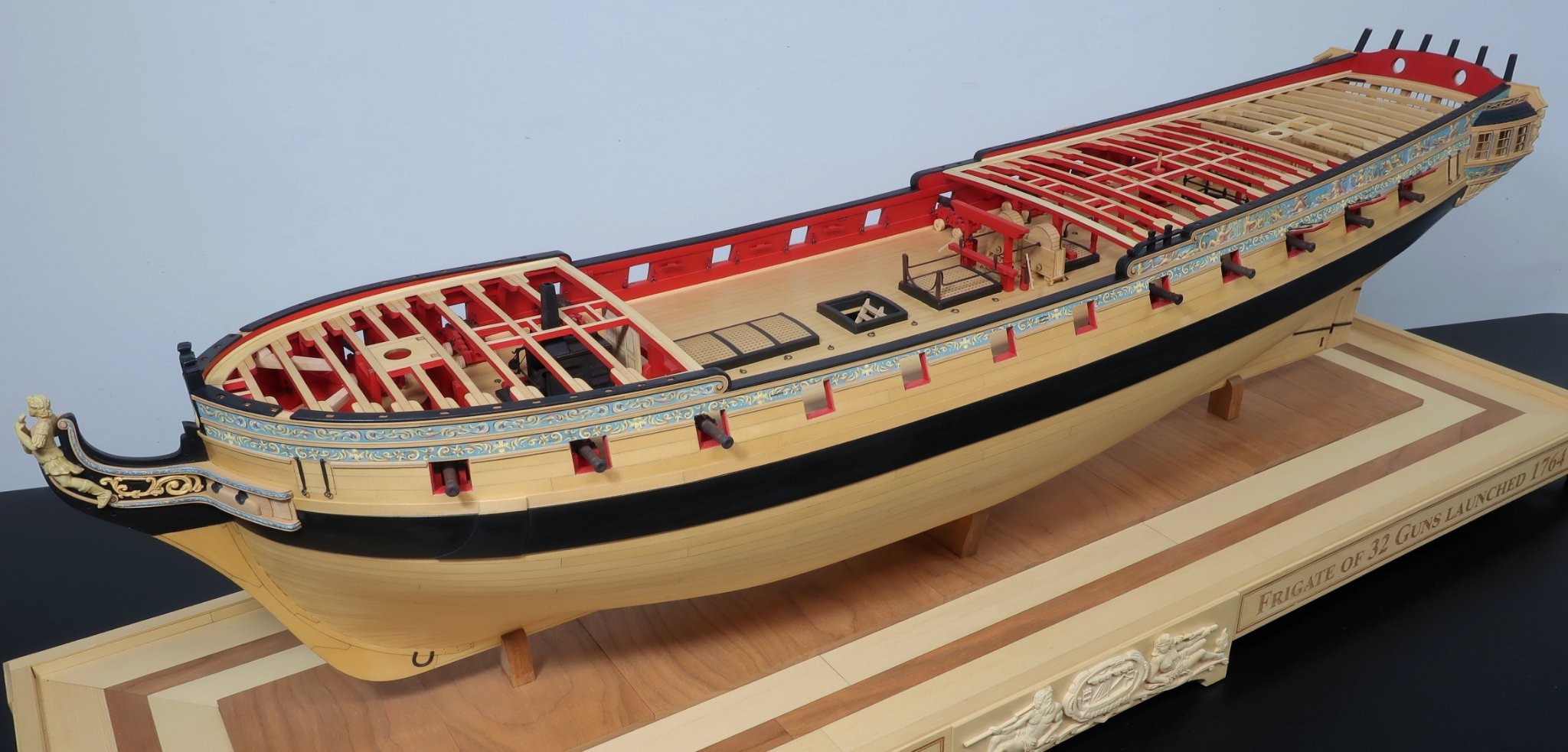
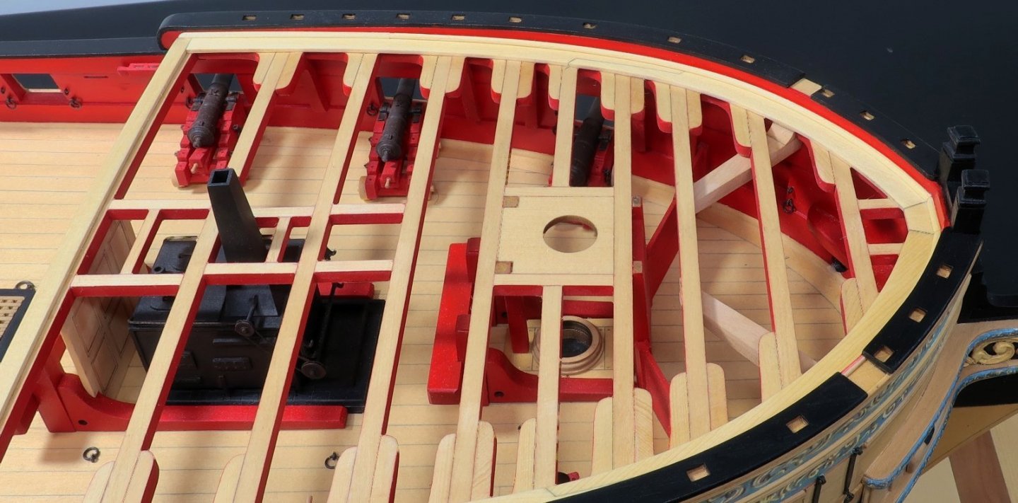
Im reposting so it doesnt get lost on the previous page I decided to plank the outside bands or belts of the fcastle and qdeck. I wanted to break up the task rather than have to do all of the remaining planking at once. I cant plank the center band until I make all the coamings and gratings etc. What I did do however was select all of the wood for the planking now so it all was a good match in color and lightness. I set aside all of the wood for when do plank down the center. You have a few options here. I will let you decide. You can rip some strips and bend them to the curves needed based on the template. Thats fine, especially for the qdeck planking. BUT, I decided to just rubber cement my template for the fcastle planking on some 3/64" thick cedar sheets. The curves are more pronounced on the fcastle. Then I just used a sharp #11 blade to cut them out. I stayed outside of the lines and then sanded them to fit tightly. There are only four planks on each side of the fcastle so it isnt too bad. Just use the template first as a paper guide and make any tweaks for your model before cutting them from wood. No laser cut and etched decking here folks!! For the qdeck I just ripped some 1/4" x 3/64" strips. Then I tapered them to match the template. I made sure the butt joints fell on a beam. Try for some nice tight seams here.....and dont forget to simulate the caulking down one edge of each strip with a pencil or whatever method you prefer. You can see that so much of the gun deck is still viewable and this will be a nice method so all those details and hard work arent hidden away below deck. Next up I will be making the coamings and gratings so I can plank around them down the center of the deck. This may take a while because I want those grating to fit perfectly in the coamings just like they did on the gun deck. That means there will be plenty of coaming thrown in the trash until they are just right.


- 1,784 replies
-
- 16
-
-

-
- winchelsea
- Syren Ship Model Company
- (and 1 more)
-
I think you will be fine Greg. Its usually just the vendors that get nicked. i believe they think we can easily take the loss. You should absolutely bring your model. I dont want to discourage you or anyone else. I think it had a lot to do with folks getting excited after two years without a show. It was a bit crazy early on at the show. My wife said folks were literally coming on our side of the tables and rummaging through the tool boxes for stuff before we even finished setting up. Those that know my set up….all syren products are on display boards and when you point to something you want to buy we go through the boxes and put together your order. But this time folks were just having a free -for -all early on who didnt know the system… it was quite chaotic. The funny thing is that after lunch the vendor tables are dead. But the first two hours are crazy.
- 1,784 replies
-
- 5
-
-
- winchelsea
- Syren Ship Model Company
- (and 1 more)
-
No worries Tim You would be surprised how often stuff gets lifted from these ship model shows. This year I also “lost” a few display cannons I had built on their carriages. i put them out on the table to show folks what they look like all assembled. Maybe these guys think they are free samples…LOL. It happens and it was even worse at a few NRG conferences.
- 1,784 replies
-
- 3
-

-
-
- winchelsea
- Syren Ship Model Company
- (and 1 more)
-
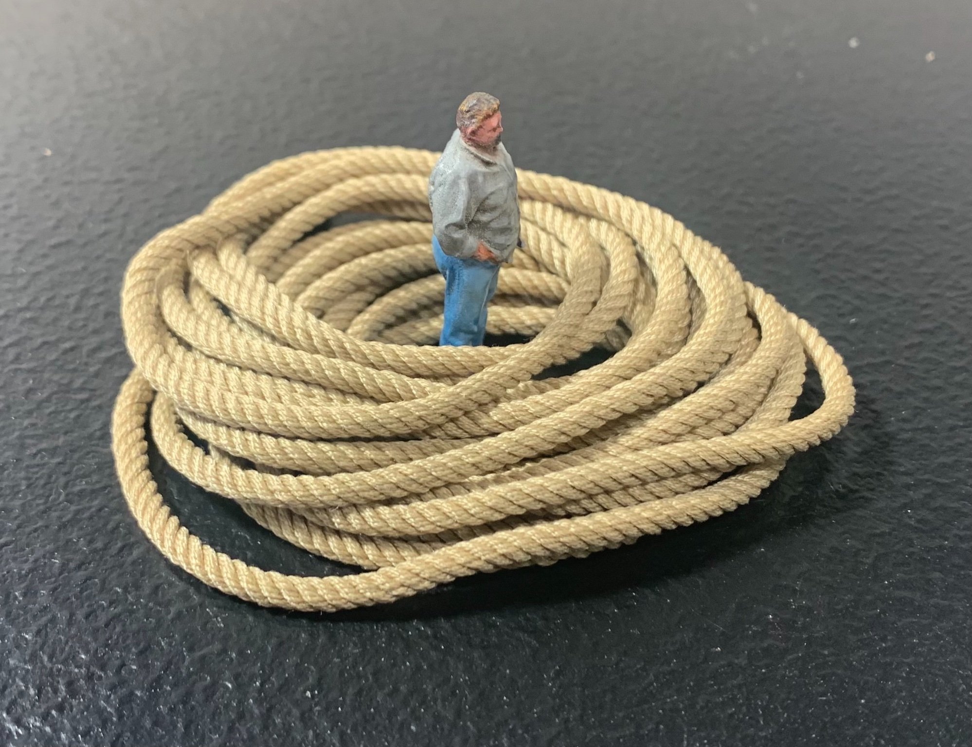
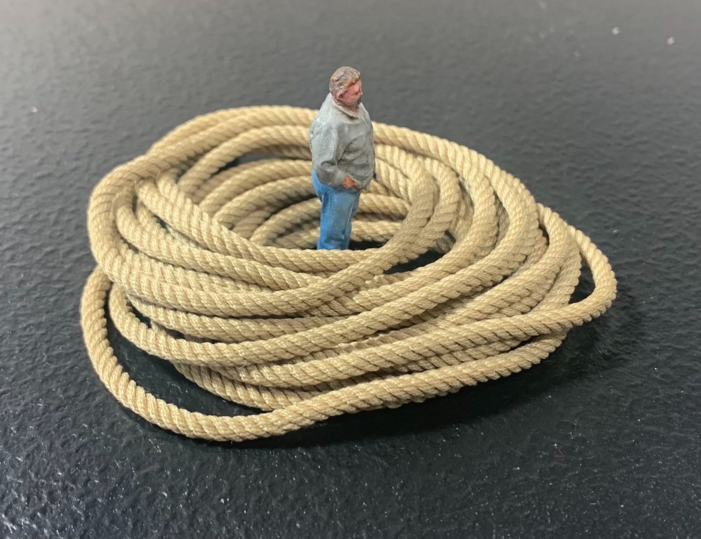
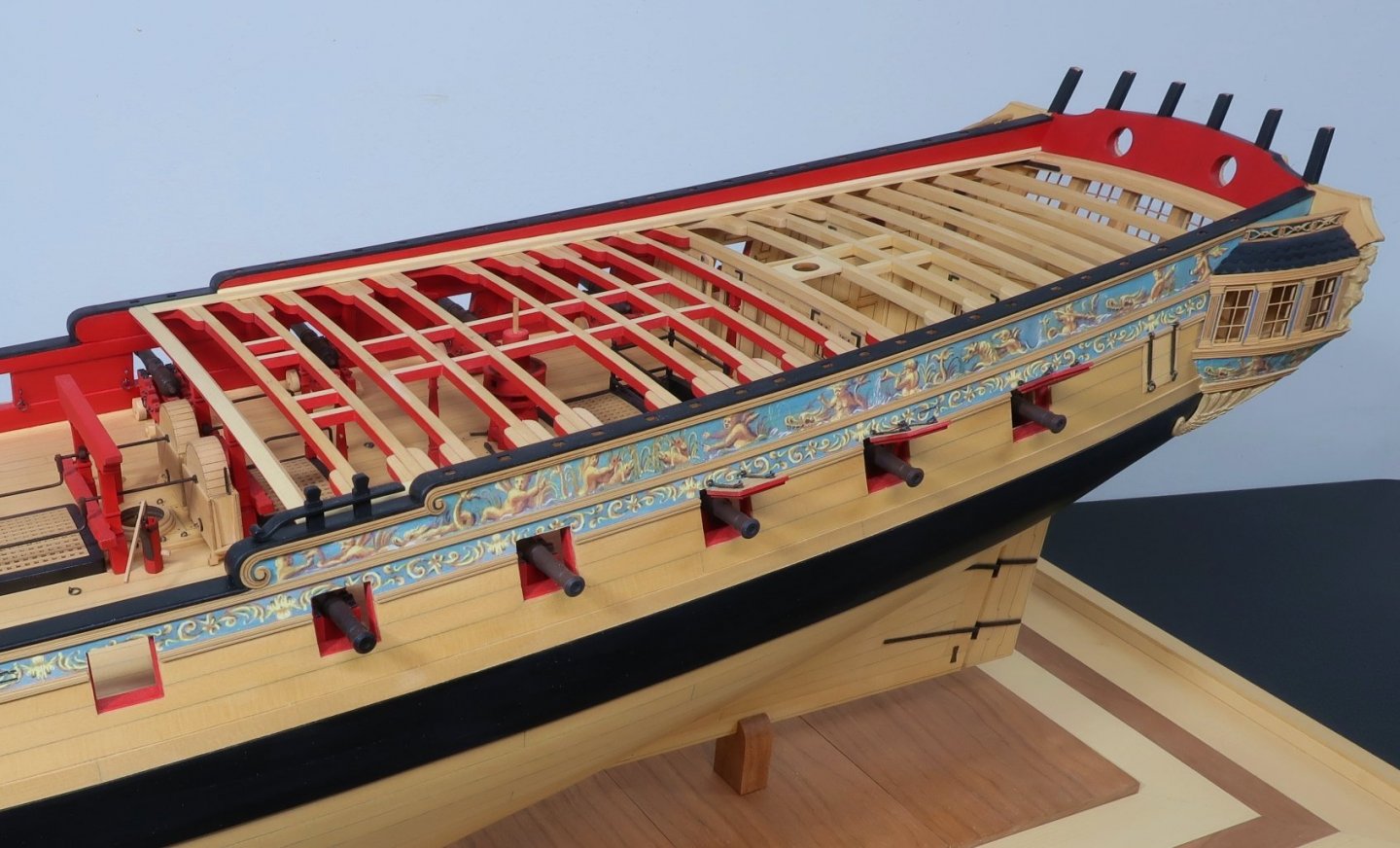
I decided to plank the outside bands or belts of the fcastle and qdeck. I wanted to break up the task rather than have to do all of the remaining planking at once. I cant plank the center band until I make all the coamings and gratings etc. What I did do however was select all of the wood for the planking now so it all was a good match in color and lightness. I set aside all of the wood for when do plank down the center. You have a few options here. I will let you decide. You can rip some strips and bend them to the curves needed based on the template. Thats fine, especially for the qdeck planking. BUT, I decided to just rubber cement my template for the fcastle planking on some 3/64" thick cedar sheets. The curves are more pronounced on the fcastle. Then I just used a sharp #11 blade to cut them out. I stayed outside of the lines and then sanded them to fit tightly. There are only four planks on each side of the fcastle so it isnt too bad. Just use the template first as a paper guide and make any tweaks for your model before cutting them from wood. No laser cut and etched decking here folks!! For the qdeck I just ripped some 1/4" x 3/64" strips. Then I tapered them to match the template. I made sure the butt joints fell on a beam. Try for some nice tight seams here.....and dont forget to simulate the caulking down one edge of each strip with a pencil or whatever method you prefer. You can see that so much of the gun deck is still viewable and this will be a nice method so all those details and hard work arent hidden away below deck. Next up I will be making the coamings and gratings so I can plank around them down the center of the deck. This may take a while because I want those grating to fit perfectly in the coamings just like they did on the gun deck. That means there will be plenty of coaming thrown in the trash until they are just right. I wanted to take pictures with the little "mini me" but unfortunately some knucklehead with sticky fingers stole it right off the model at the Connecticut show. I wonder what the guy is doing with a mini me? I shudder to think. Rest in peace "mini me". So far no ransom note has been sent.
- 1,784 replies
-
- 22
-
-
-
- winchelsea
- Syren Ship Model Company
- (and 1 more)
-
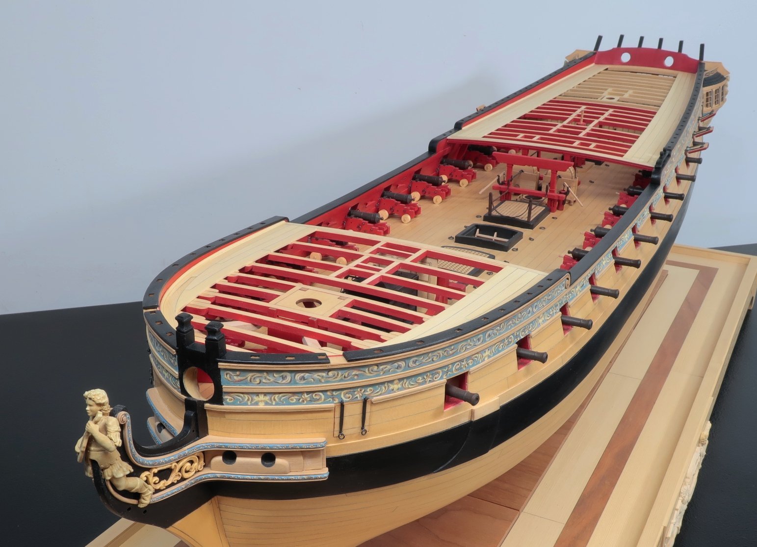
Lovely model. Thats a nice Syren.
-
US Brig Syren by Gahm - Model Shipways
Chuck replied to Gahm's topic in - Kit build logs for subjects built from 1801 - 1850
Beautiful work. That will be a beauty when completed. -
Its going to be a while. You are too quick for me. How about the gunport lids….did you make those yet? I am making steady progress now so hopefully soon enough. But you will run through Chapter 9 and be ready for ten really quickly too.
-
Wait until you plank the counter and then fair the hull back there into the counter planking so it will be smooth. The line is fine and what you really need to do is sand and fair that filler against the bulkhead former.

-
It looks fine actually. It is more of a gentle curve on that line that follows the curve of the bottom of the lower counter. This is east enough to draw on those filler pieces so you can plank correctly and once you actually plank the lower counter with the laser cut parts that curve will become very evident. The laser cut counter olanking will create the actual curved shape. Its absolutely fine as I see it and its good to see you working on her again.
-
How is your Winnie progressing? Any progress?
-
Beautiful progress. That is one cleanly built model. Nice work.
-
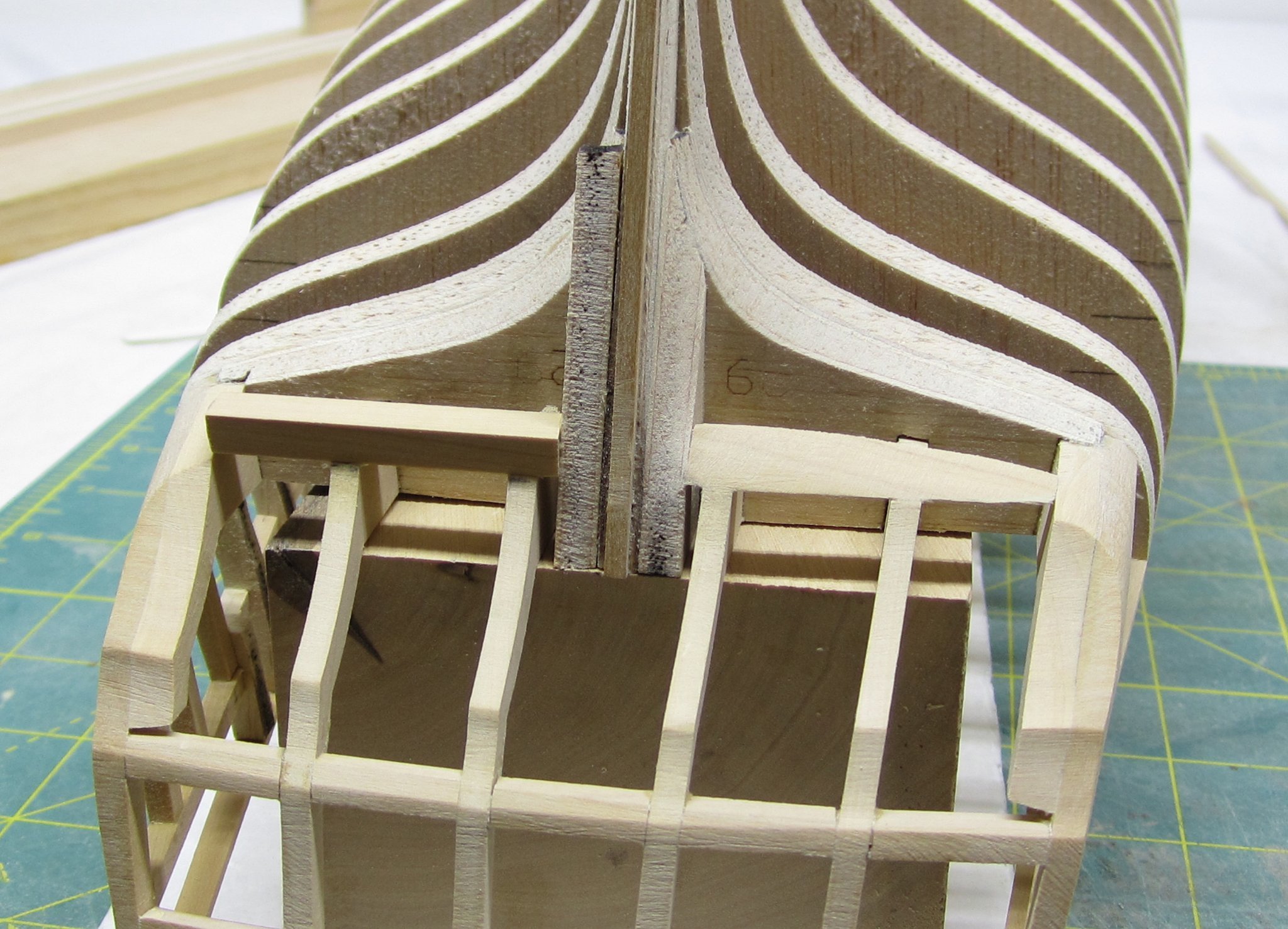
Yupp….even though 95% of the parts are laser cut in this kit. It is impossible to match the curvature at the bow for everyones model. Everyones model will vary slightly and even from the port to starboard sides on the same model based on how I see evryone fairing the bow area. So its best to just cut your own. its not that hard and this way everyone wont toss and waste all that wood when the laser cut pieces dont fit….you have my templates which is basically spoon feeding the shape I would have laser cut. If you test the template on your model and it doesnt fit correctly then the laser cut Versions would just be trash. Its why the model looks like it does and not the typical kit like pieces that dont fit. Its only one of the very few pieces you have to cut on your own.
- 1,784 replies
-
- 4
-
-
- winchelsea
- Syren Ship Model Company
- (and 1 more)
-
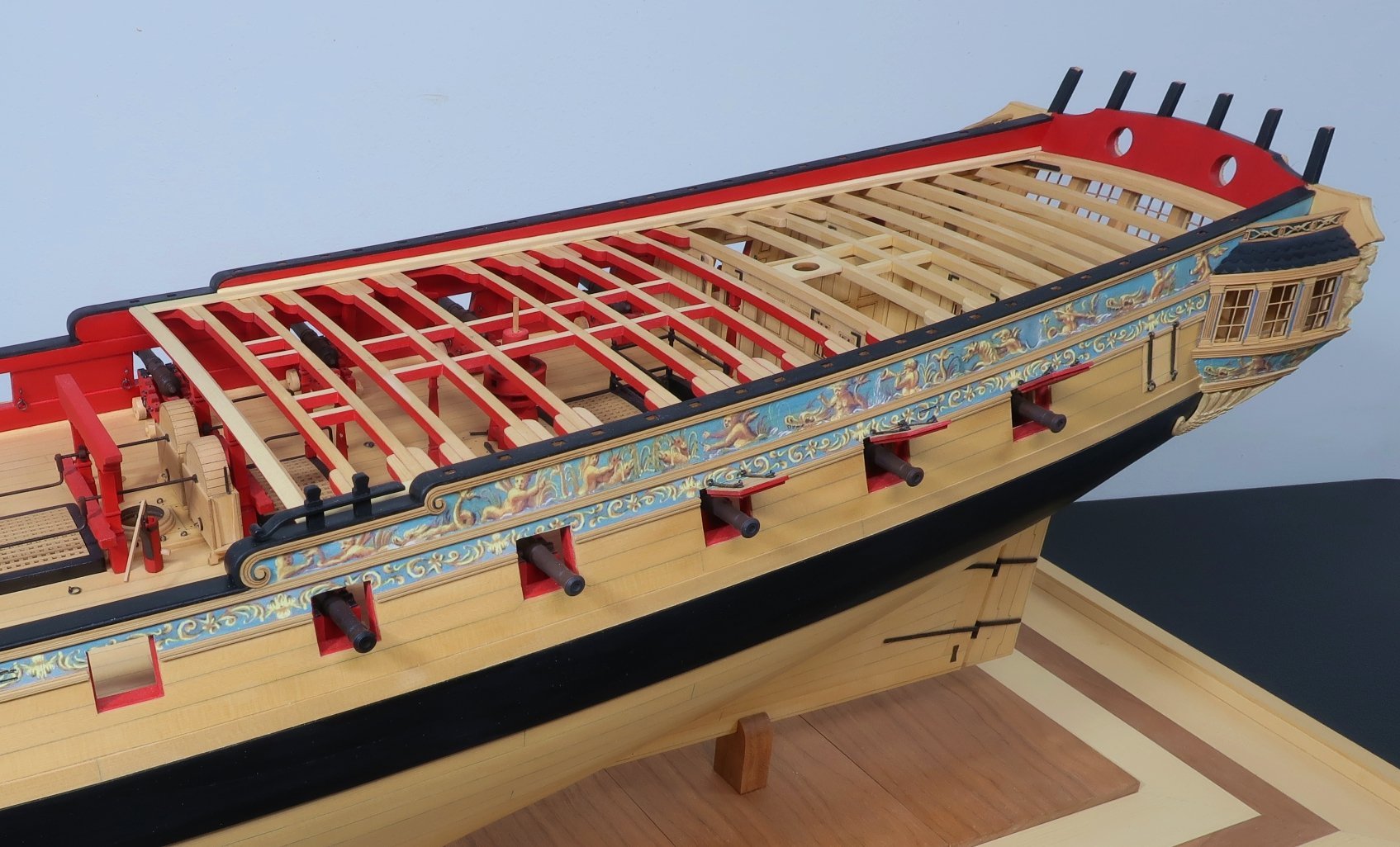
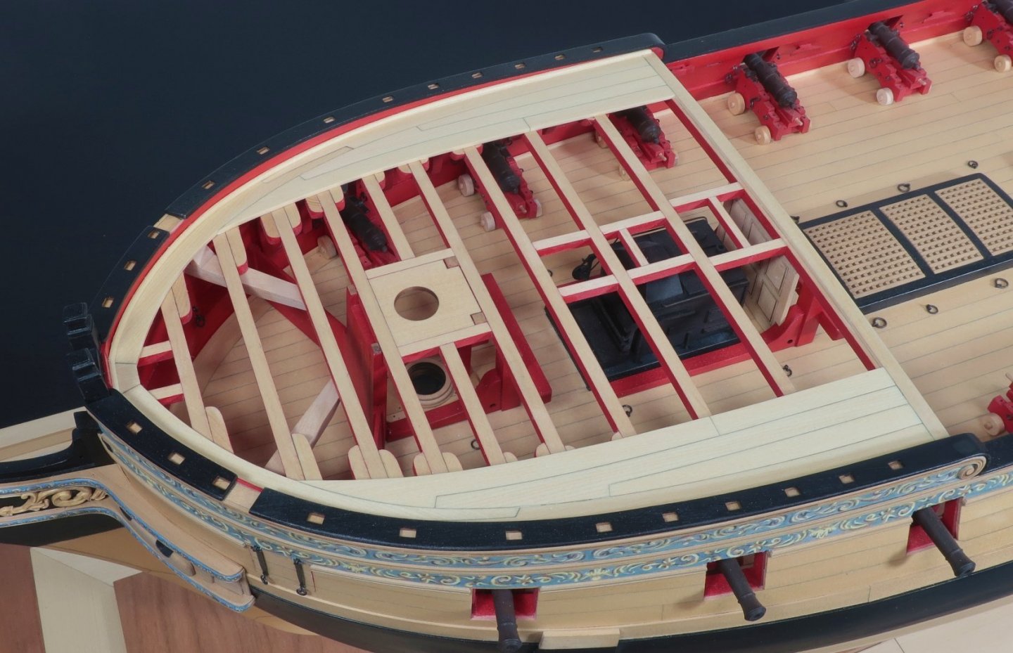
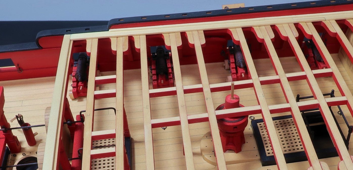
Here is a quick update. The margin planks on the qdeck and fcastle have been added. The first planks to add are those along the breast beams at the waist. I used a 3/16" x 3/64" strip for this. The overhang edge on both were rounded off. There is only a slight overhang on the breast beams with these plans which should leave you with a nice rabbet on the other side for your deck planking which we will start shortly. The rabbet was about 1/16" wide on the other side. Fcastle margin planks shown below. Then the templates can be used as a starting point for the actual margin planks. Just like you did for the gundeck below at the bow. Use the template as a guide and starting point to make your margin planks. I cut them from a 3/64" thick sheet. Then I added the waterway along the bulwarks just as we did on the gun deck. I 3/64 x 364 strip was used and one corner was rounded off down its length to create a quarter round profile. Same as for the gun deck....you dont have to create scarph joins if you dont want to. They are tricky. You can simply butt them together if you want to simplify this. Then the same was repeated on the qdeck. Start with the breast beam plank.....then the waterways can be cut from a 3/64" sheet......and then make the waterway from a 3/64 x 3/64 strip. Do you guys have any questions???? I thinking I will start on the outside areas of planking before I do the coamings. Just to break up the planking process a bit. Again .....you guys have the templates for lining off. All the deck planks are provided for you on the templates for the fcastle and qdeck. It should go easier than the gun deck. I will have that done soon and another update.

- 1,784 replies
-
- 20
-
-
-
- winchelsea
- Syren Ship Model Company
- (and 1 more)
-
Looks great so far....Welcome to the group.
-
Thats not a little update. They take a long time to make neatly. They look great. Chuck
- 642 replies
-
- 3
-
-
- winchelsea
- Syren Ship Model Company
- (and 1 more)
-
Very Good....Looks like you will be a very busy modeler. I am looking forward to seeing both models progress.
-
It all looks very good. The guns look great rigged. The hinges are neat and tidy. Chuck
-
Looking good Bob...
-
Lovely work....
-
CAF is OK but ZHL is not. I have deleted the video because it had all kinds of ZHL advertising. It should not have been posted. Tom stopped making this model for a while. There were issues with the design and bulkheads not fitting properly, etc. Again I suggest you contact Tom for details directly. But it looks like he is offering it again so I can assume he has fixed all of the issues with the design. Chuck
-
Looks great Mike...Cant wait to see it all painted and weathered. Chuck
- 607 replies
-
- 2
-
-
- winchelsea
- Syren Ship Model Company
- (and 1 more)