HOLIDAY DONATION DRIVE - SUPPORT MSW - DO YOUR PART TO KEEP THIS GREAT FORUM GOING! (Only 51 donations so far out of 49,000 members - C'mon guys!)
×


michael mott
-
Posts
5,198 -
Joined
-
Last visited
Content Type
Profiles
Forums
Gallery
Events
Everything posted by michael mott
-
 Mauro that you are doing the sewing by hand shows your skill with the materials, very nicely done. Michael
 -
Ben I think we all tend to use them until they just don't cut well or most often break because they are dull and then overheat. perhaps a small label like the oil change one on the car. Blade good for x number of board feet of cutting. Michael
-
Nice to see the re purposing of some packaging material. Michael
-
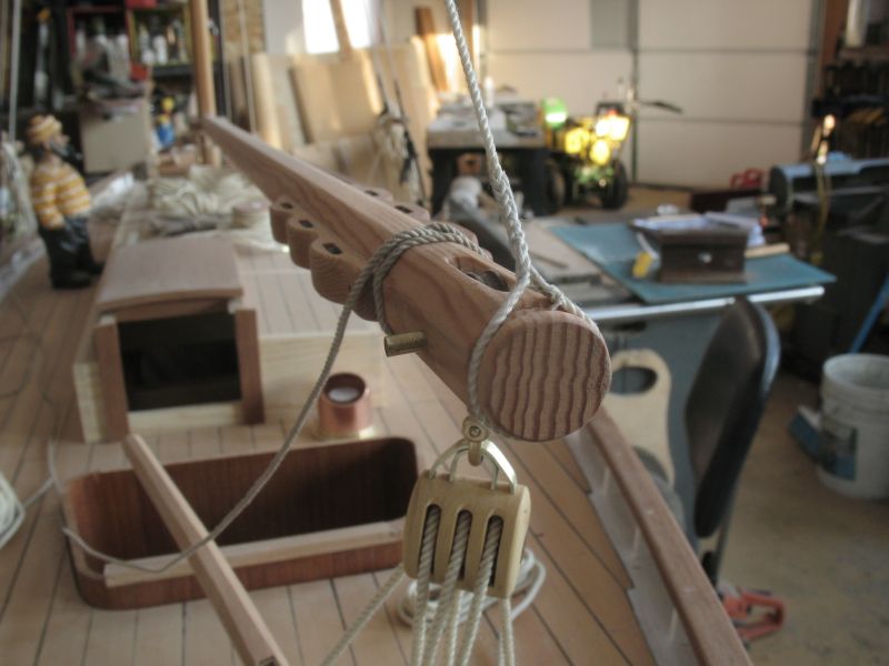
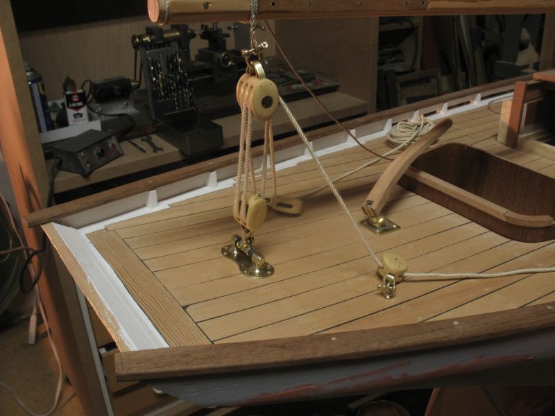
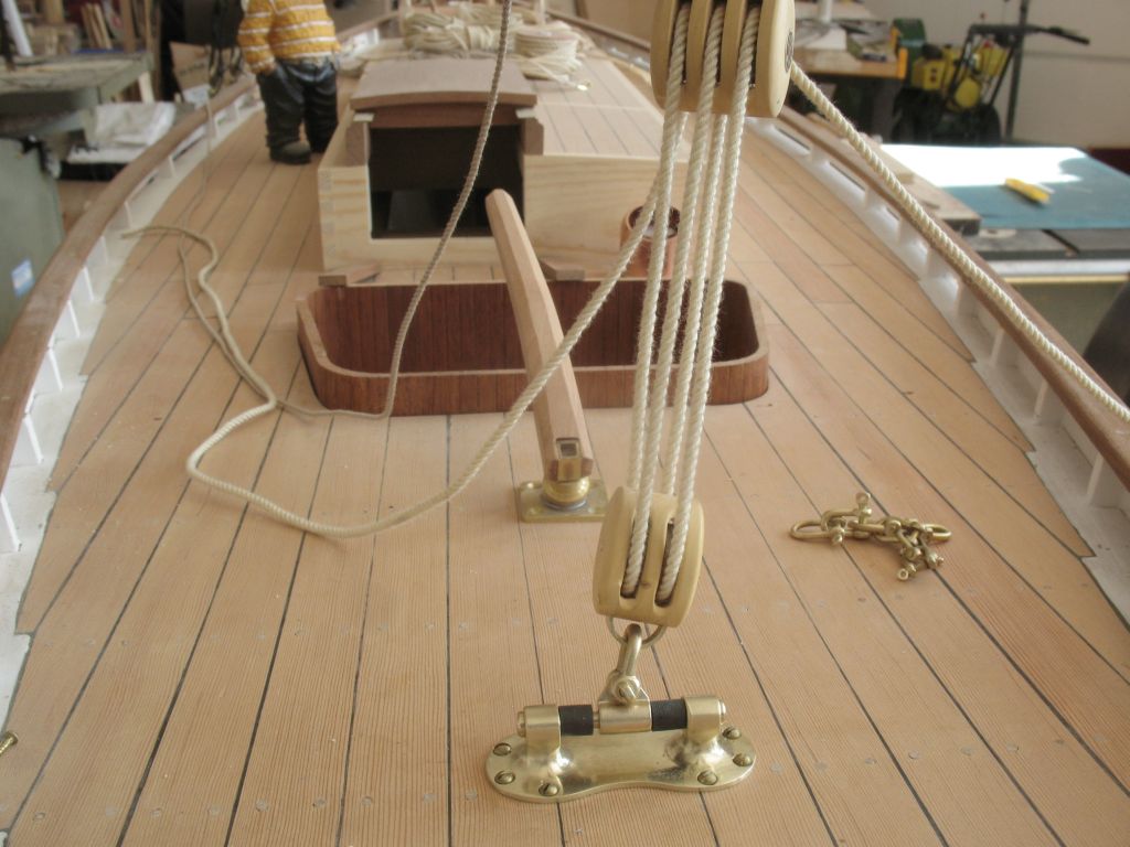
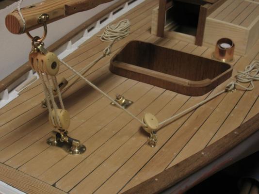
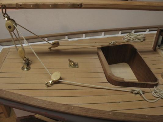
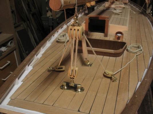
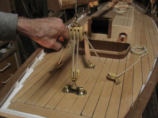
I rigged up a couple of drums to test my thoughts about this, I used the camera to make a video clip here The drum is only about 4 inches in diameter I used a couple of discs of oak left over from a project they rotate 6 times from centre to full swing. I think I will be able to make this work, In all my sailing I have never used a main sheet rig like this so I was unfamiliar with the actual mechanics of the way it would work. I full scale I would think that the double set of cleats gives the person working the sheet more control by letting out one or other sides for when the added leverage is needed and then using both at the same time lets out the main faster. That is the way it appears to me anyway. The deck cleats did double duty as guides, but I think a couple of fair-leads would be useful I am thinking that for display the sheets can be coiled up and when sailing they could be led into the cabin in some simple way. Michael
-
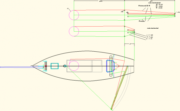
This is an area that I have been ruminating over for some time now. Bob I think that there has to be a way to make the main sheet work in a similar way to the full size practice. This is a schematic of the mainsail sheets and a clearer PDF kingfisher main sail control.pdf I am thinking that if I have 2 drums that are 6 inches in diameter or 2 6 inch that are stacked with the boom centred and three turns of sheet on each drum and that both drums run in sync so that both port and starboard sheets can let out at the same time then I lessen the distance for the sheet on either side by half. Michael
-
Only one crew sleeping? Michael
-
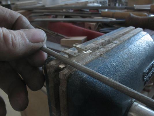
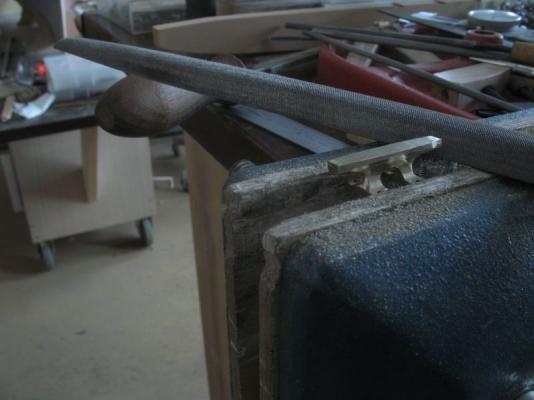
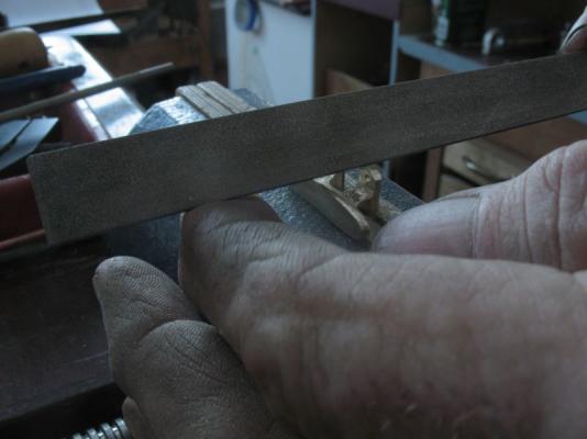
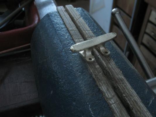
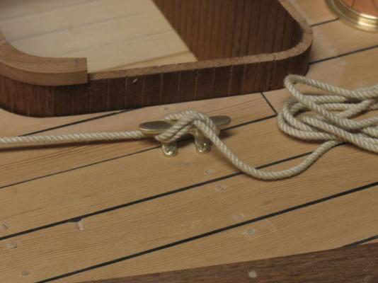
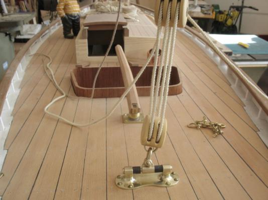
Thanks S.os, Nils, Bob, Used to sail, for your kind remarks, and for all those who added likes. The last two pieces of the main-sheet tackle the cleats for the port and starboard main sheets. These were rough milled with a 1/2 inch end mill and a 1/4 inch ball end mill, then drilled for the # 0 deck screws, I also made a countersink out of some 5/32 drill rod because I had nothing small enough to get to the hole past the top part of the cleat. A series of files were used to shape the cleats the following pictures are pretty self explanatory. Here I am showing the large half round for shaping the top of the cleat, the flat file has a safe edge, it was handy for supporting the file with my fingers when shaping the bolt tabs The finished rough filed cleat ready for the fine needle files and for the emery and steel wool All mounted, I did have to reshape the heads of the #0 countersunk wood screws a little. I made them into quasi oval heads by setting up a wood mandrel in the chuck to hold the screws while a very fine file rounded the tops and reduced the diameter a few thou. Now to deal with the rudder. Michael
-
This one area that concerns me regarding my own build. It is very informative following along with you build and seeing how you solve the various operational issues. She does look good sitting in the water. Michael
-
Harriet McGregor by Boccherini
michael mott replied to Boccherini's topic in - Build logs for subjects built 1851 - 1900
Grant the foredeck planking is beautifully done. Michael -
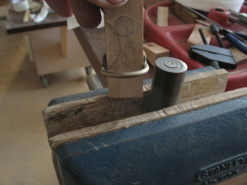
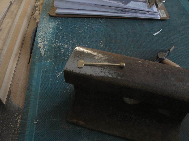
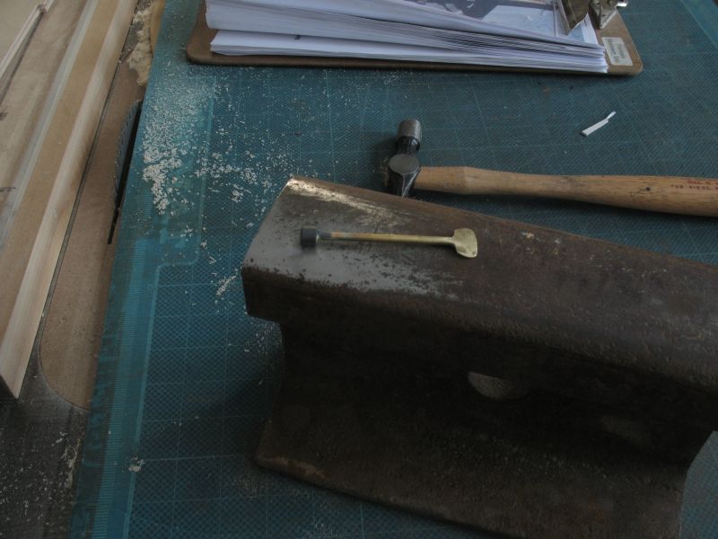
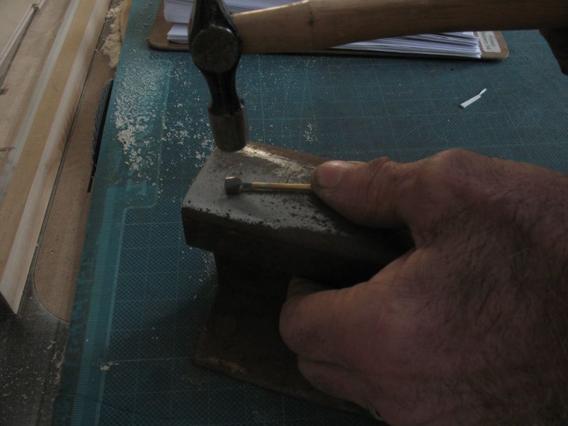
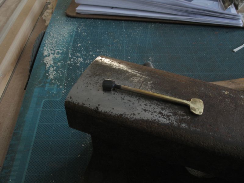
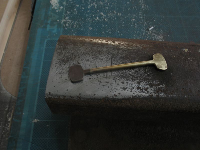
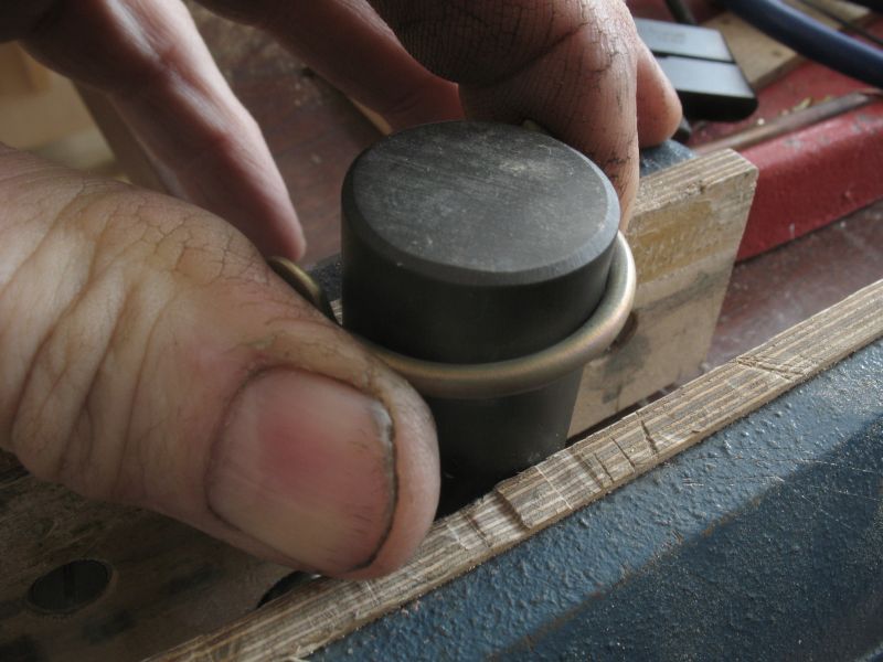
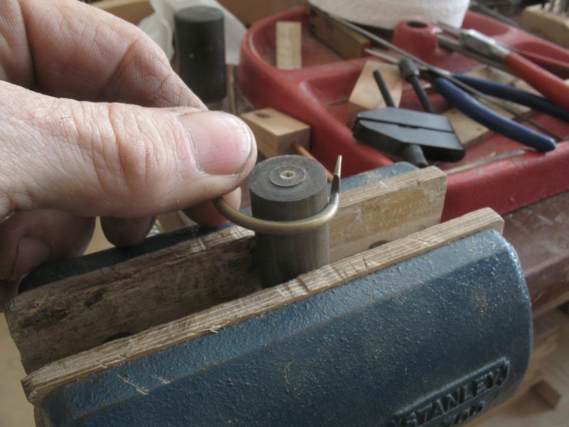
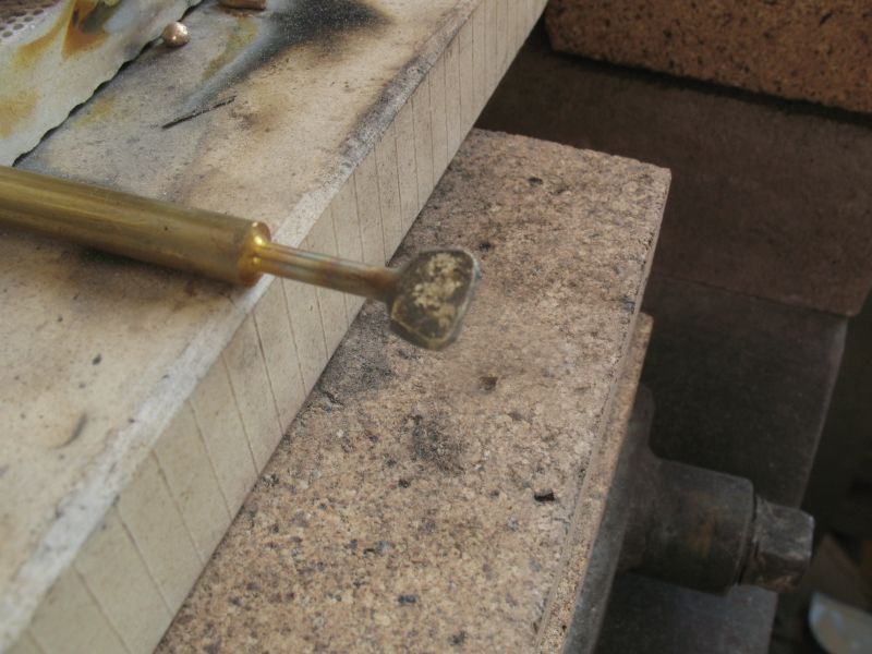
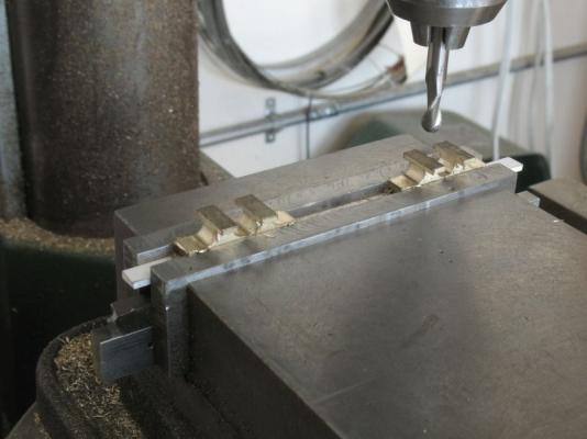
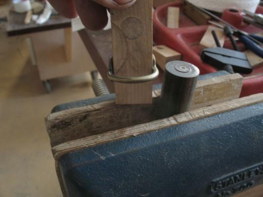
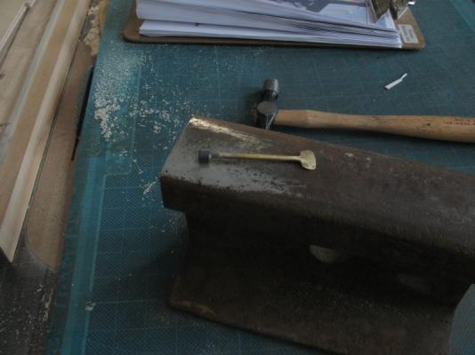
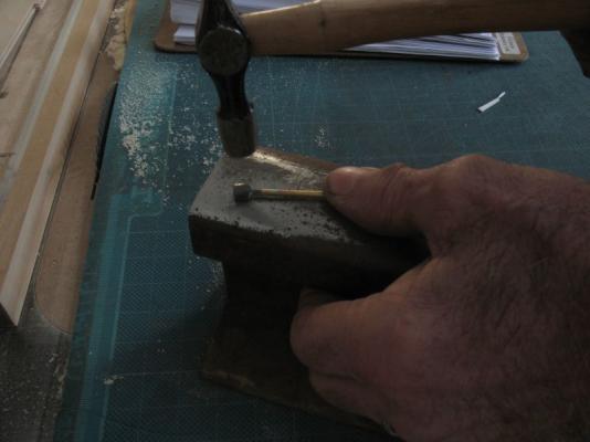
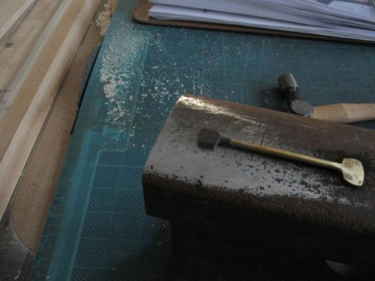
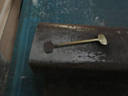
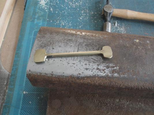
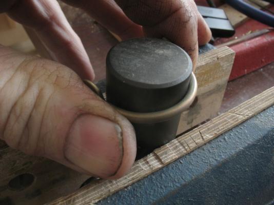
Again thank you all for the kind comments and for all the likes. Mark To answer you question, The original test piece was annealed at the other end. then a small hammer was used to flatten the end after about 6 or 7 blows the brass has become work hardened After a second annealing and another 6 or 7 hammer blows the step was repeated because again the brass becomes work hardened a third time for the annealing and another 10 or so blows, as the metal flattens a larger area needs to be hammered so it takes more blows, the weight or force of each blow remains pretty constant from the beginning to this this point, one gets into a rhythm just like any other repetitive task. A fourth time was repeated as before, to get the new end similar to the first. on this test piece (I did not accurately measure both full diameter lengths at each end because they were done at different times, on the piece that is attached to the boom the ends were both turned before the flattening to ensure the same volume of material would squash out.) After a clean up with the wire wheel the centre portion is annealed to soften it to be bent around a piece of rod. The rod diameter need to be close to the final shape because there is very little spring to the brass after it is annealed, as it is bent it begins to work harden again which is good because the final shape needs to be hardened enough to retain its shape. the aluminum scrap here is 1 inch in diameter next a smaller diameter piece of wood was used, it was a conveniently smaller diameter, to close in the ends a little tighter than the main curve then the piece was squeezed onto the block of maple that I used for the final one that is on the boom this was so that the drilling could be done without the piece deforming any more. The drilling was explained in the last entry in the build log. I hope this helps to see how easy some of these tasks are when you break them down into their small steps. 1 Turn to diameter 2 heat to soften (annealing brass, heat to red then quench in cold water) 3 shape with hammer 4 reheat , as many times as needed to gain the desired amount of flattening 5 shape to final form 6 machine holes and finish shaping with files. 7 polish with emery and steel wool. Michael


-
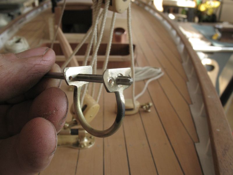
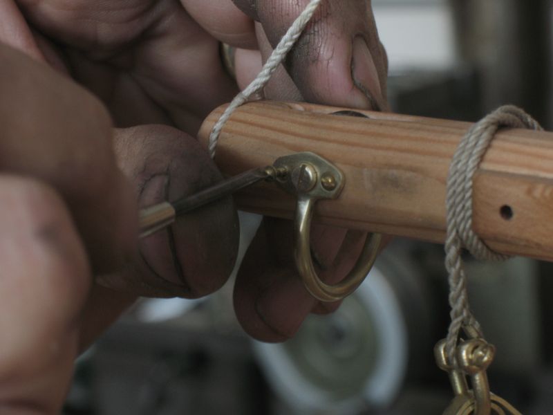
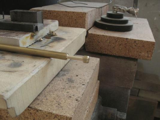
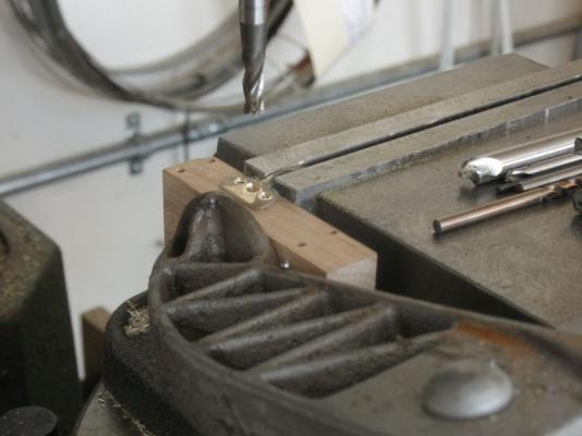
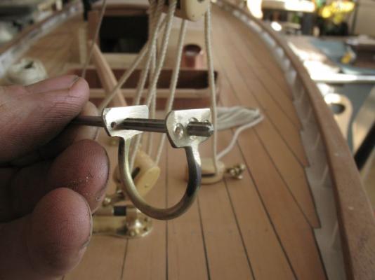
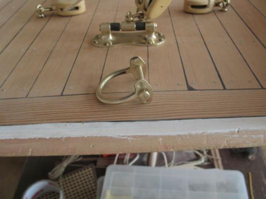
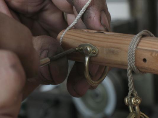
pop by anytime Jay the tea kettle is always on. One of my own little fantasies Bob. Sherry I love working with both materials, the beauty of boat models is the variety of materials that one gets to work with. Keith thank you for you very nice commentary about my build log. One of the most important things for me is to understand the how and why of what I am making and if my account of what I am making is helpful then the sharing is worth the time it takes. I feel so much more informed from all the amazing builds on this forum that my own knowledge expands every day I log in. John Thanks for your kind words Ah mark its all smoke and mirrors. Thanks for the compliment. Today was a fun day I finally finished the main sheet attachment to the boom. First I did a forging test with some 1/4 inch brass stock I necked down about 3/4 of an inch to about 1/8th leaving a 1/4 inch long full diameter at the end. this was annealed and forged on the railroad anvil four times to flatten out the end. After seeing that the forging would work for what I needed, a length of 1/4 inch rod was cut to 2 1/2 inch length with the centre necked down to the 1/8th diameter. both end were then forged to the same shape as the test piece on the railroad track anvil. after bending the curve into the smaller diameter (if I were to make another I would make it about 1/4 inch shorter) the unit was set up in the vice for drilling. A block of maple the same width as the boom was sandwiched between the ends to support the brass flange while the holes were drilled and then counter-bored to create flats in the slightly tapering flattened flange. The centre hole is 1/8th to allow a brass Chicago screw to replace the pin holding the clew out-haul sheave. next the hole was reamed to ensure they were aligned. after clean up. removing the temporary pin. fixing the new tackle Done Michael


-
HMS Bounty by UdoK
michael mott replied to UdoK's topic in - Build logs for subjects built 1751 - 1800
The frames are looking good Udo, good to see that you solved the issues that were troubling you. Michael -
Very sharp Bob, so is that some heat resistant paint that you used? Michael
-
Wow Mark that looks really outstanding. very nice work on the dovetails as well. Michael
-
Bob answered the question that I was going to comment on. I just checked in for the first time, what a great job you are doing Bob, I love the 3d drawings, your "rough sketch" is pretty nice too. Having only just gotten a rough hang of 2d spline curves I somehow don't think 3d cad is in the cards for me. i will be following along with your build. Michael
- 86 replies
-
- 2
-

-
- muscongus bay lobster smack
- Midwest Products
- (and 1 more)
-
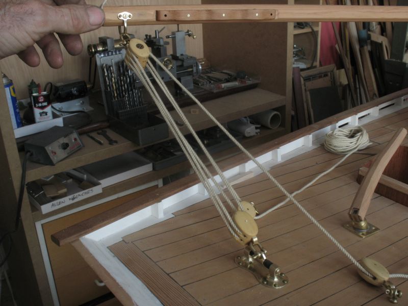
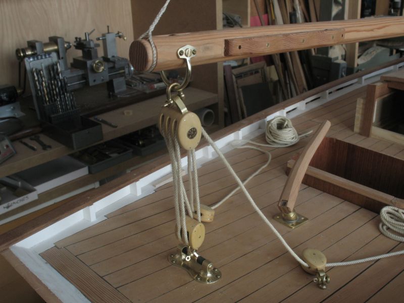
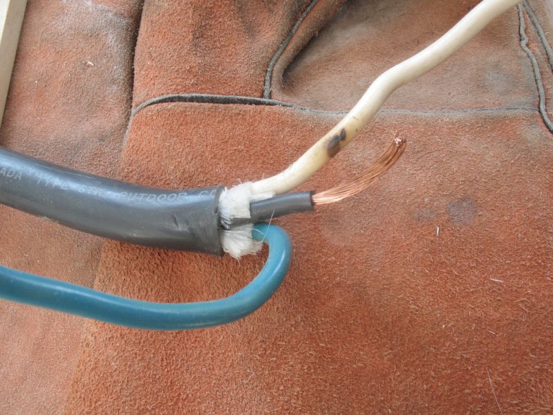
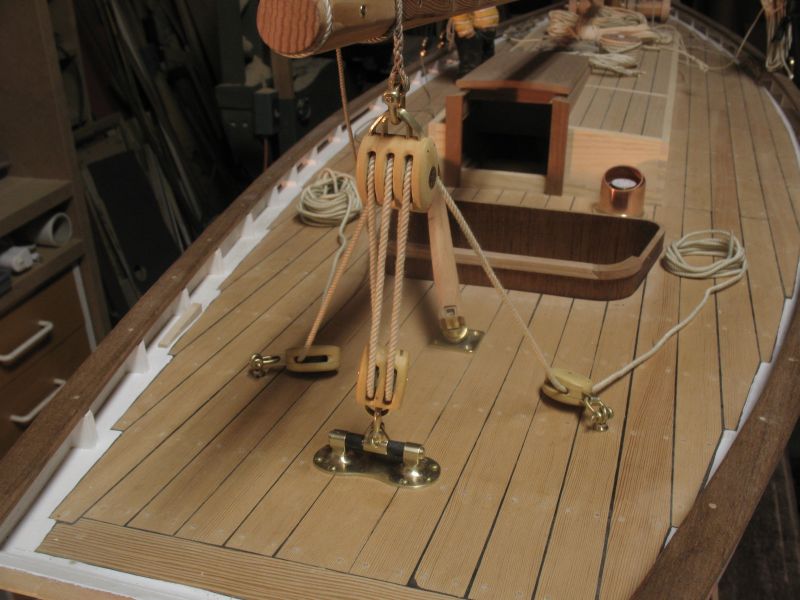
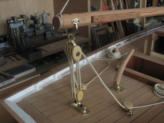
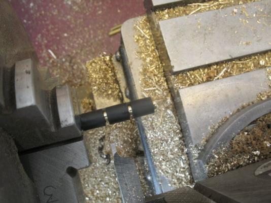
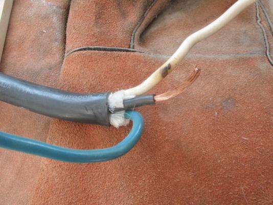
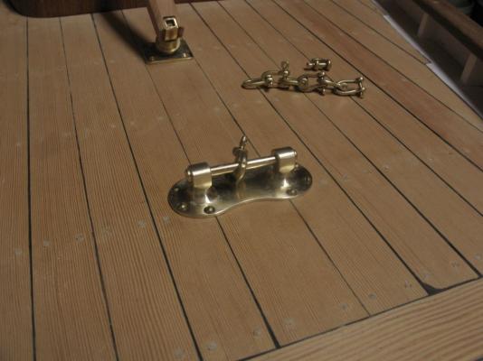
I had posted this last night but.... Again thanks for all the positive comments and for the likes. Yesterday I finished up the deck part of the main sheet tackle. first I used some rubber like insulation from some heavy wire. I slipped about 3/4 of an inch onto some 1/8th inch diameter brass rod and parted it off into some 1/4 inch long sections. then made the small sliding part after grinding up a form milling cutter. after fitting it up I spent the rest of the day making the two single blocks and fitting them to the deck. I swung out the boom to finish threading the rope plus I wanted to see how much rope I would need it turned out to be almost 18 feet, with about 1 foot laying on each side of the cockpit as part of that distance. All I need to do to finish the main sheet control now is to add either a couple of cleats to the deck or to set in some bits and also to fit a proper bit of hardware to the boom. I have also been looking at the whole way the rudder assembly is fitted and the way it penetrates the deck. The tiller attachment area is a bit small and I don't like the fact that it is fixed. Michael

-
These learning curves whack us at the least opportune moments don't they! I look forward to the rebuild Daniel Michael
-
My sentiments exactly. Michael
-
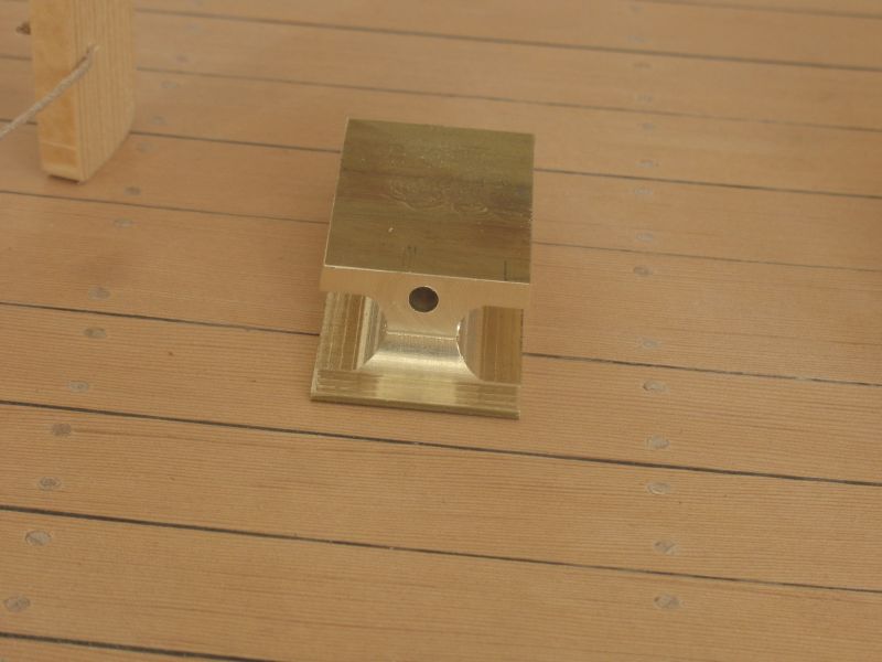
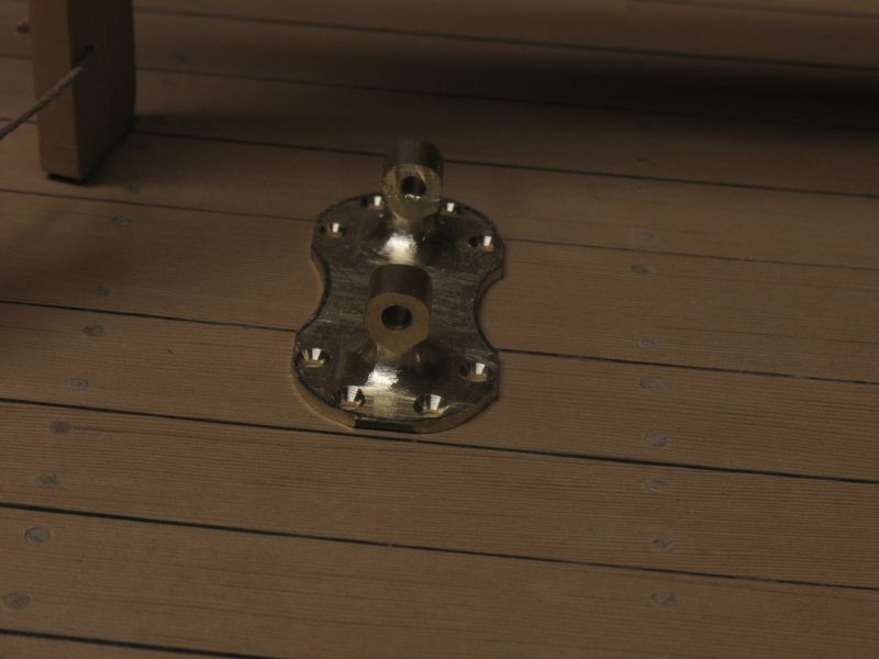
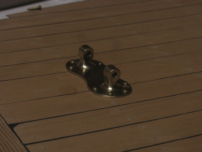
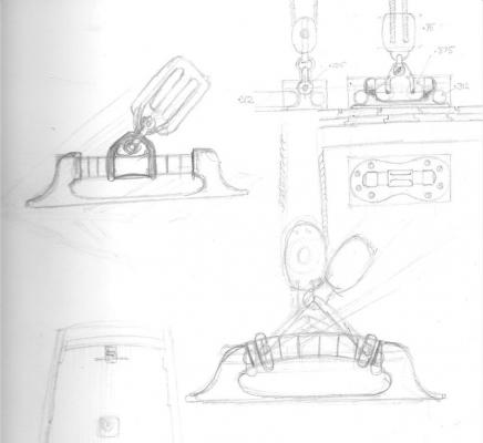
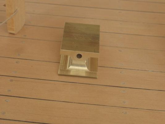
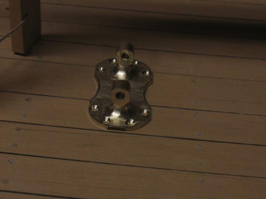
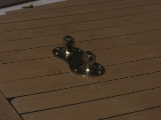
Thank you all for your kind remarks and for all those who pushed the like button. I did a little work today on the bracket to hold the main-sheet tackle to the deck. First some sketches after looking at a few on the web. the block of brass was 2 inches by 1/2 inch by 7/8th inch. using a 5/16 ball end I roughed out the main block. Then with files after the rest of the machining got the block to the final shape. A little more work with finer files and some wet and dry sandpaper then a buff in the dremmel A pin machined down from some 3/16th with a 2x56 thread for the cap end. Next the central unit that will be sandwiched between some rubber buffers each side, that the shackle and lower block attach to. Michael
-
Dan very nicely done, good clear information an interesting result regarding the contact cement. What brand did you use and do the museum folk have some documented recommendations regarding the use of this type of glue? Michael
-
Very nice looking model I like the way you tackled the sails and the ships boat. Michael
-
Toni your ship is really beautifully crafted, congratulations on your milestone. Michael