

tlevine
-
Posts
1,936 -
Joined
-
Last visited
Content Type
Profiles
Forums
Gallery
Events
Posts posted by tlevine
-
-
-
-
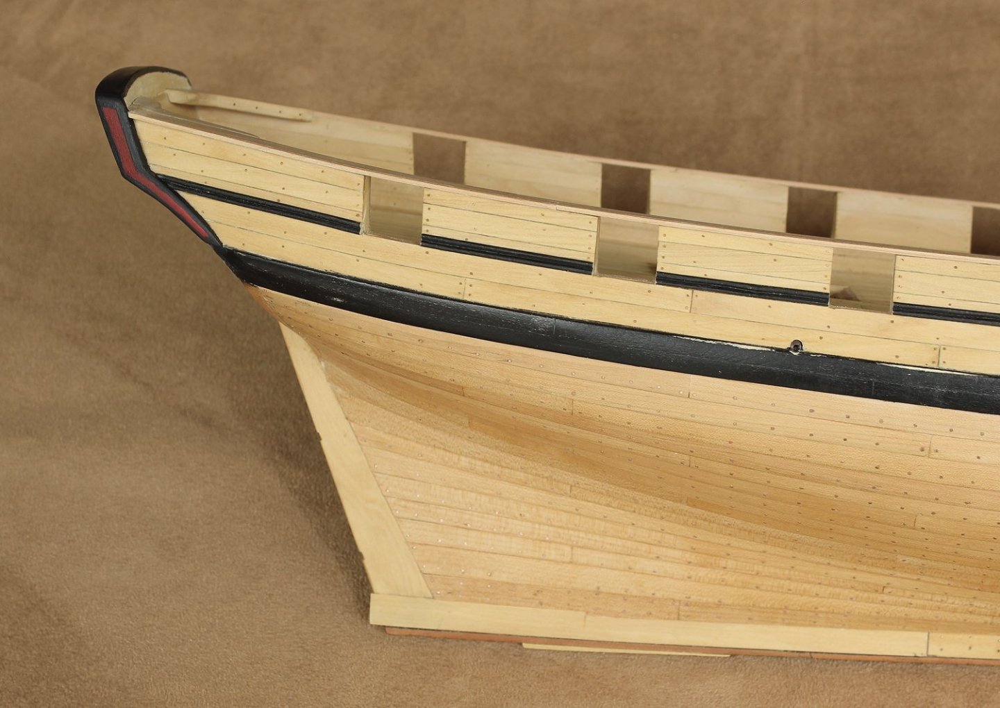
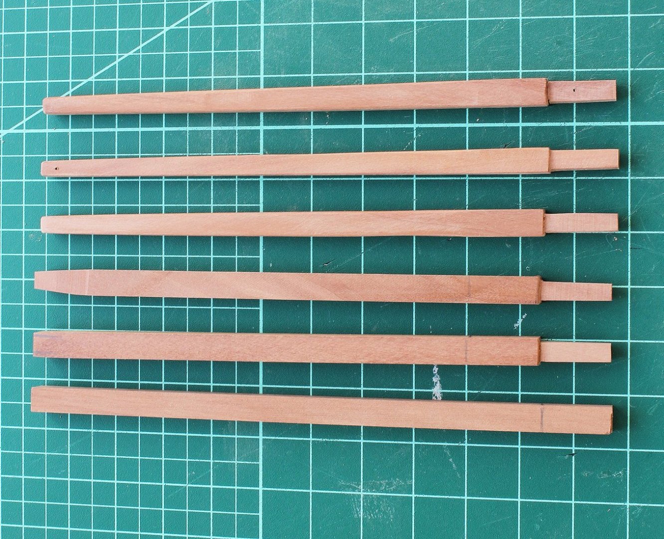
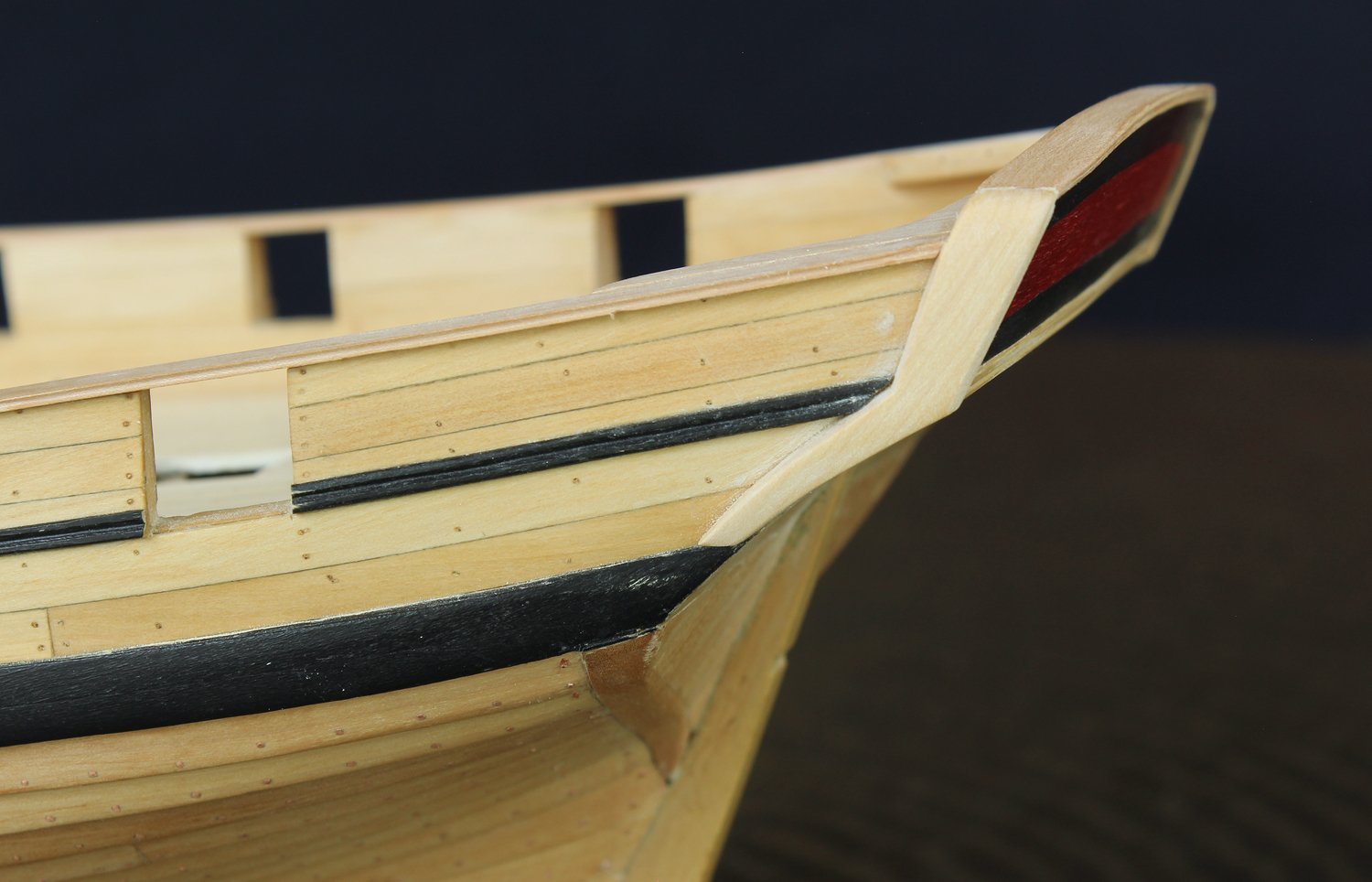
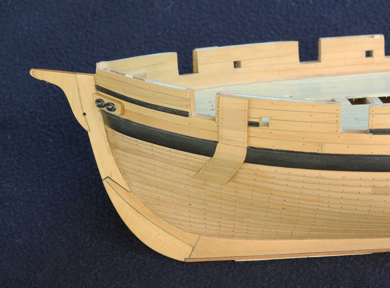
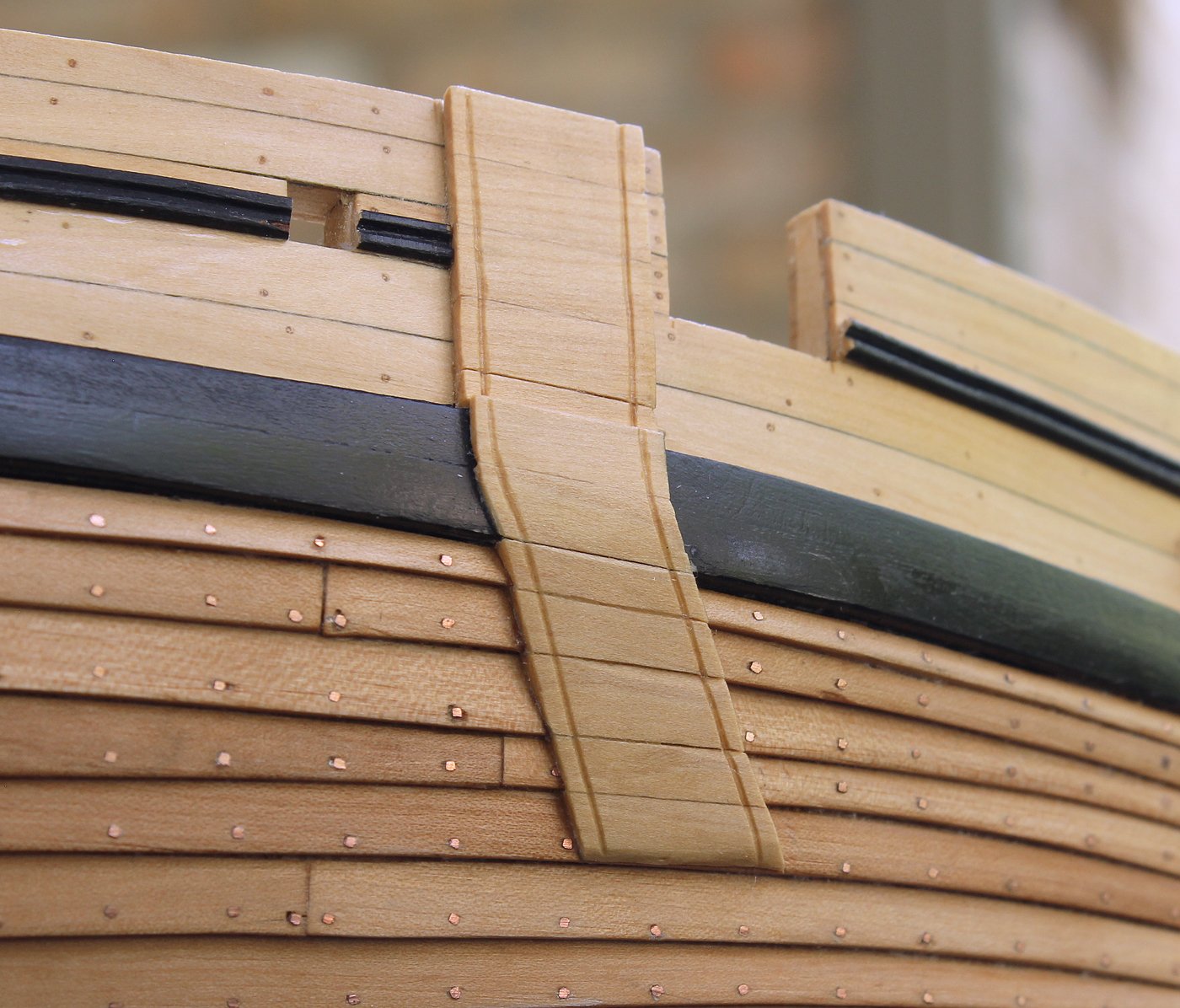
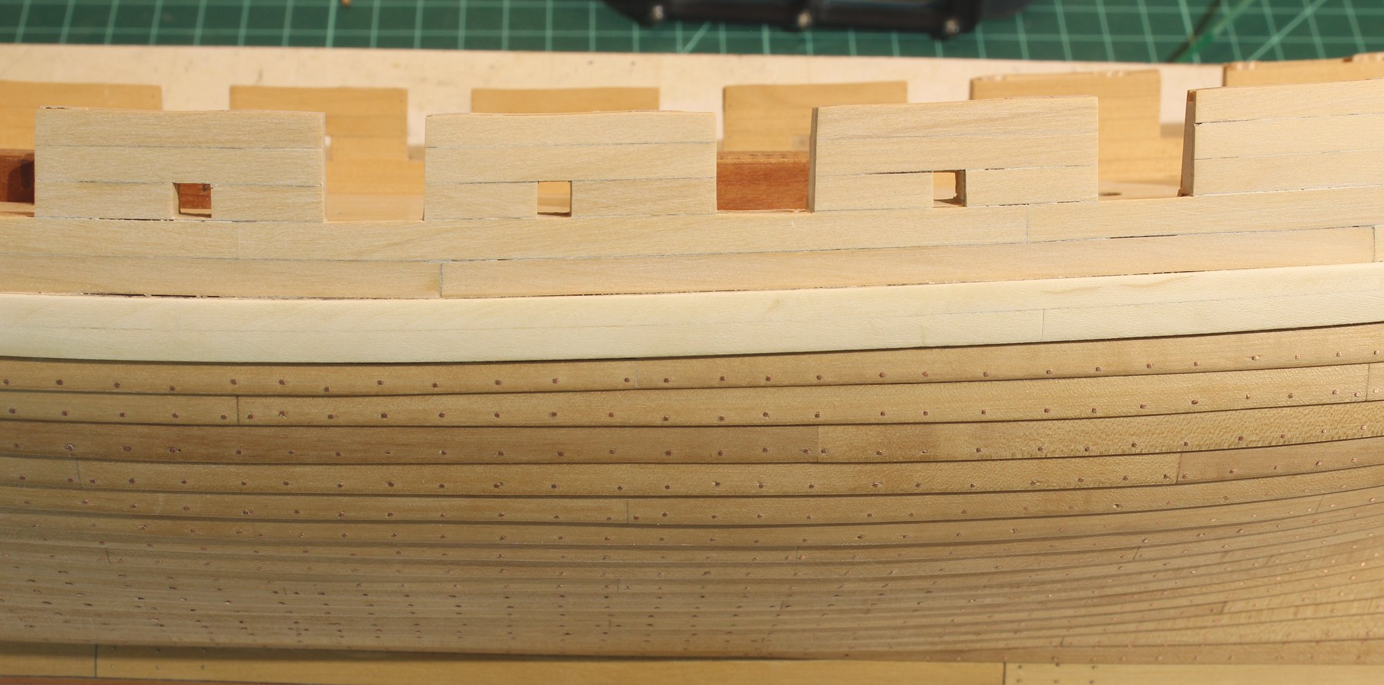
The plankshear was installed next. These planks are 2.5" thick, are flush with the inner planking and extend 3" beyond the outer hull planking. Each plank is approximately 15 feet long and ends in a scarf joint. A simple double-beaded edge was made with a scraper. I made them from pear, the same wood the lower hull planking is from, for a slight contrast in color. The knees at the stern have also been installed. The capping rail was shaped by wetting it and clamping it in place overnight. The edges were then shaped, putting the same edge treatment on the stern side. The fashion pieces were cut down to their final height and the corners rounded over.


The bollard timbers help secure the bowsprit. A dowel wrapped in sandpaper (the bowsprit) was temporarily installed and the bollard timbers were sanded against the dowel to get the correct shape.

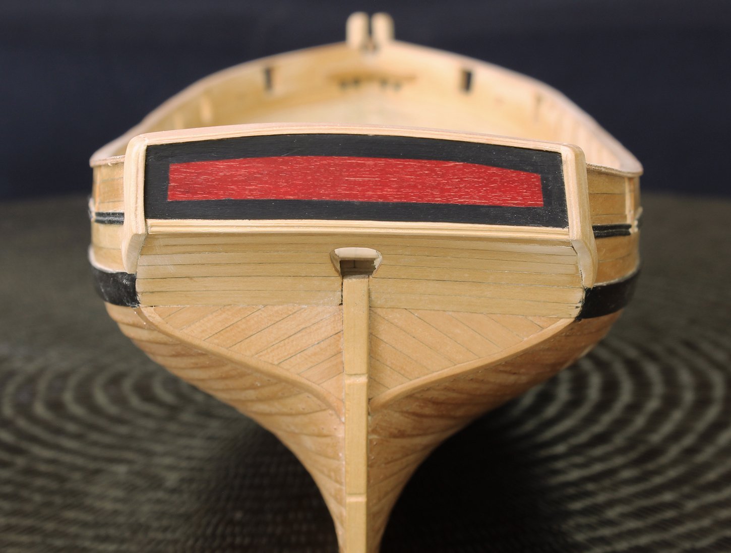
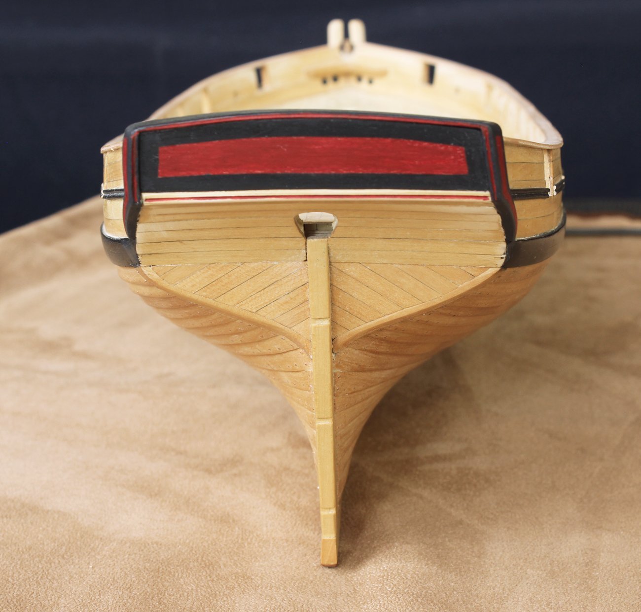
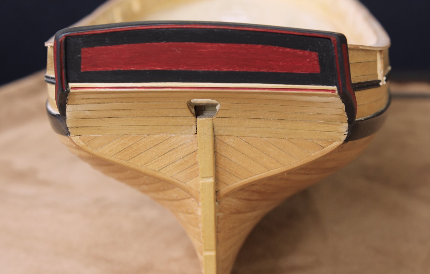
I had been trying to decide on how much decoration to show on the model. The model in the RMG has a lot of fancy work, including gold leaf. Considering the type of ship, I thought a little bit of painting was appropriate but just at the stern. I wanted a pop of color and so decided on black edging with a field of red. The double bead motif was extended onto the aft end of the fashion piece. The mottled appearance of the red is the wood grain. I made this from pear.

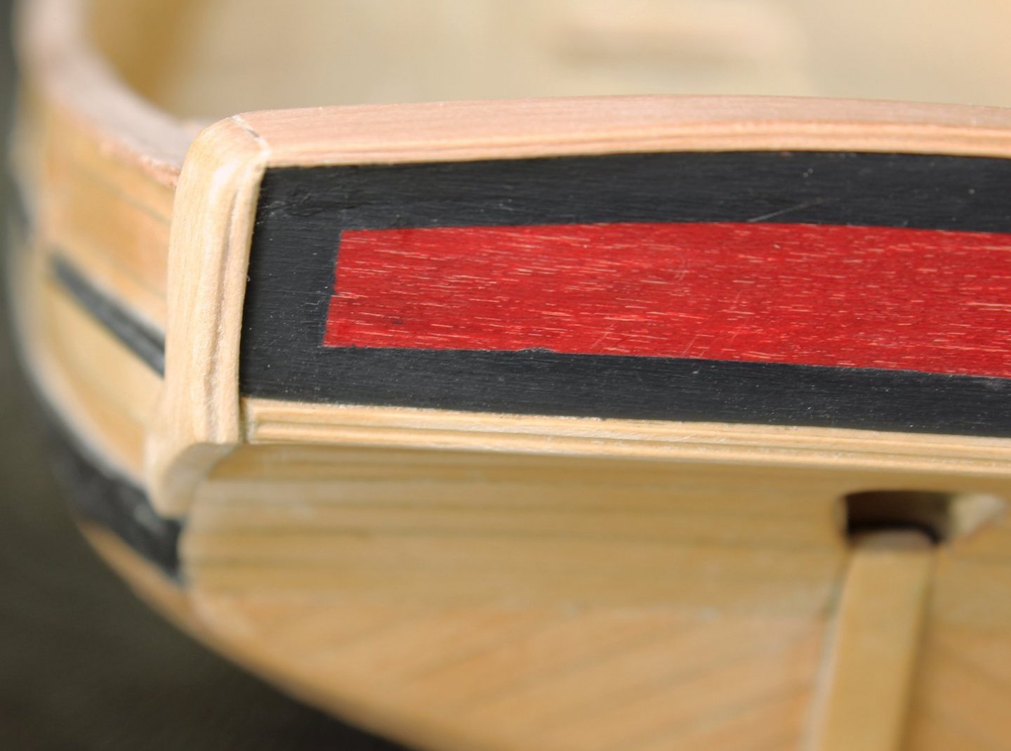
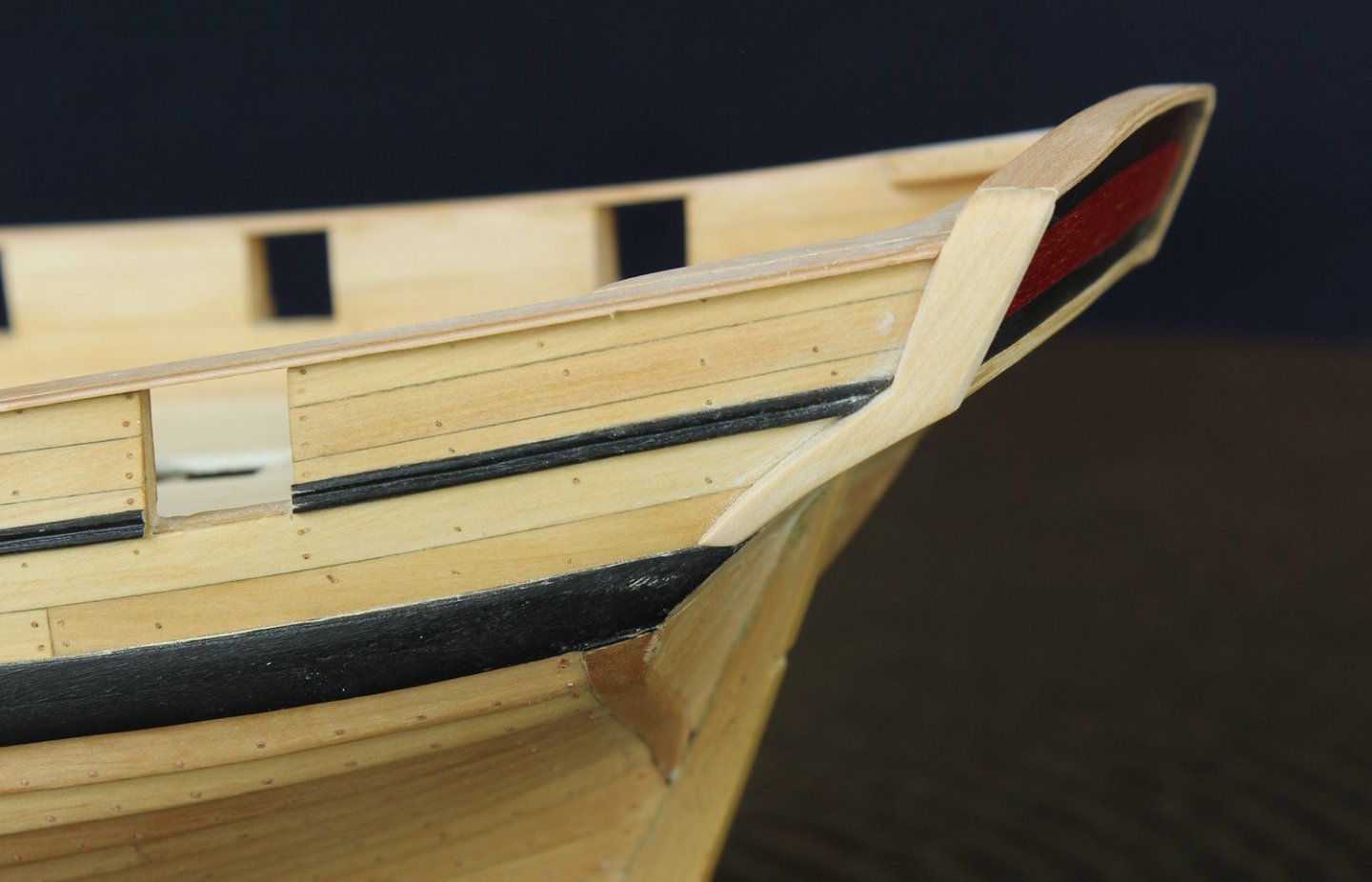
The black extends over the capping rail. The same paint pattern was put on the fashion pieces. Just for fun, I added red to the depths of the double-beading.


-
Mike, your cutter looks very nice.
The purpose of the half hull project was to teach beginners how to plank a hull. Because the planking is a standard thickness, it can be removed and replanked a few times for more practice. Never say never but at this point I do not have any plans to produce another half hull project. If I do, the builder could choose between clinker and carvel planking. Swallow has spent too much time being ignored while developing the capstan project. She is a bit jealous and demands that I finish her before doing anything else.
-
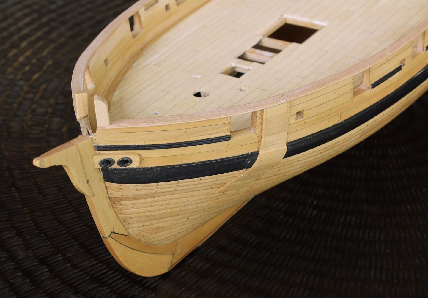
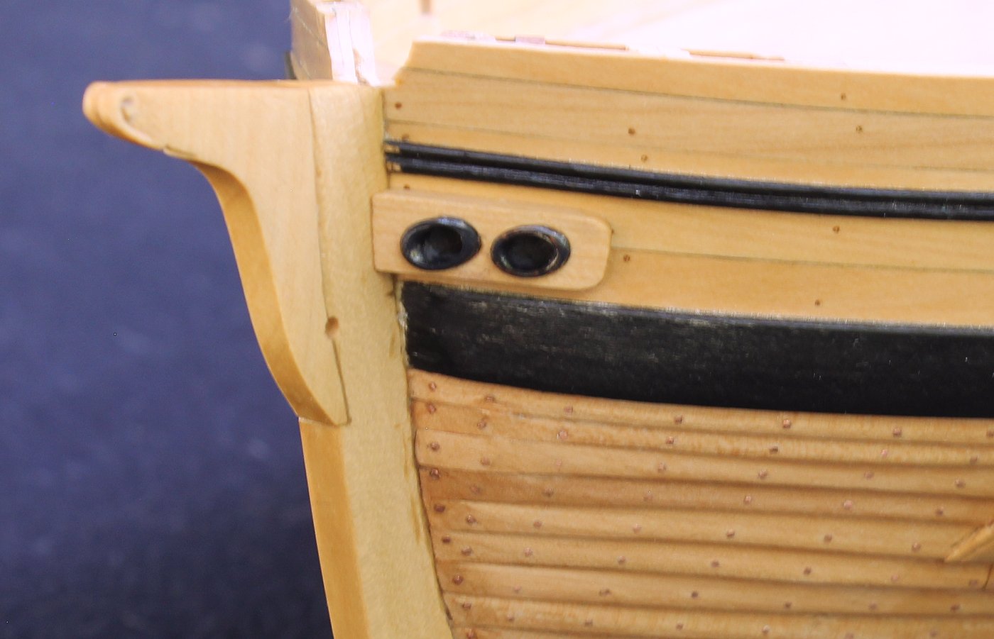
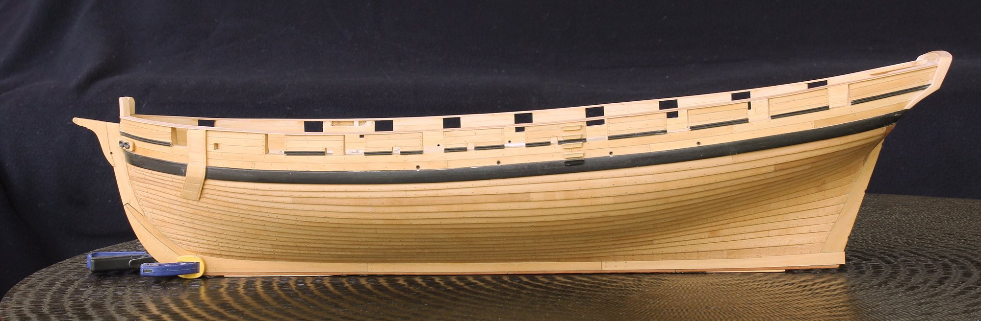
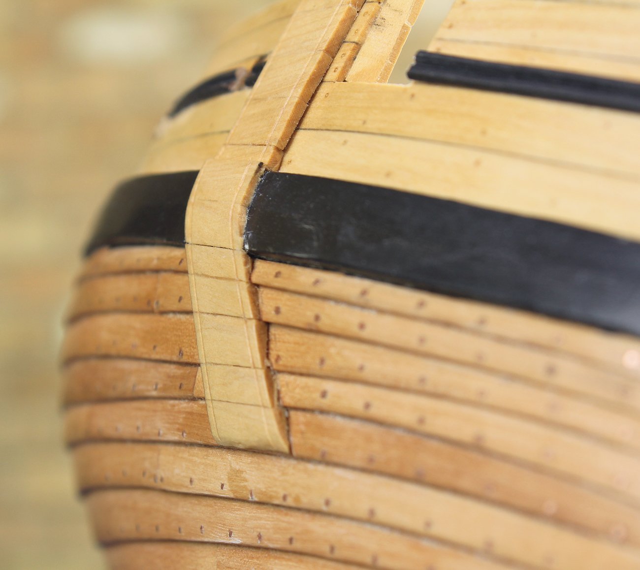
The anchor lining is a very prominent comma-shape on the model. The lining is not shown on the plan but I decided to follow the model. The upper part of the lining extends to the plankshear. It extends over the wale and continues down almost to the water line. These boards were added clinker-style but the outboard surface of the lining is smooth. There is also a smooth transition from the lower hull over the wale.
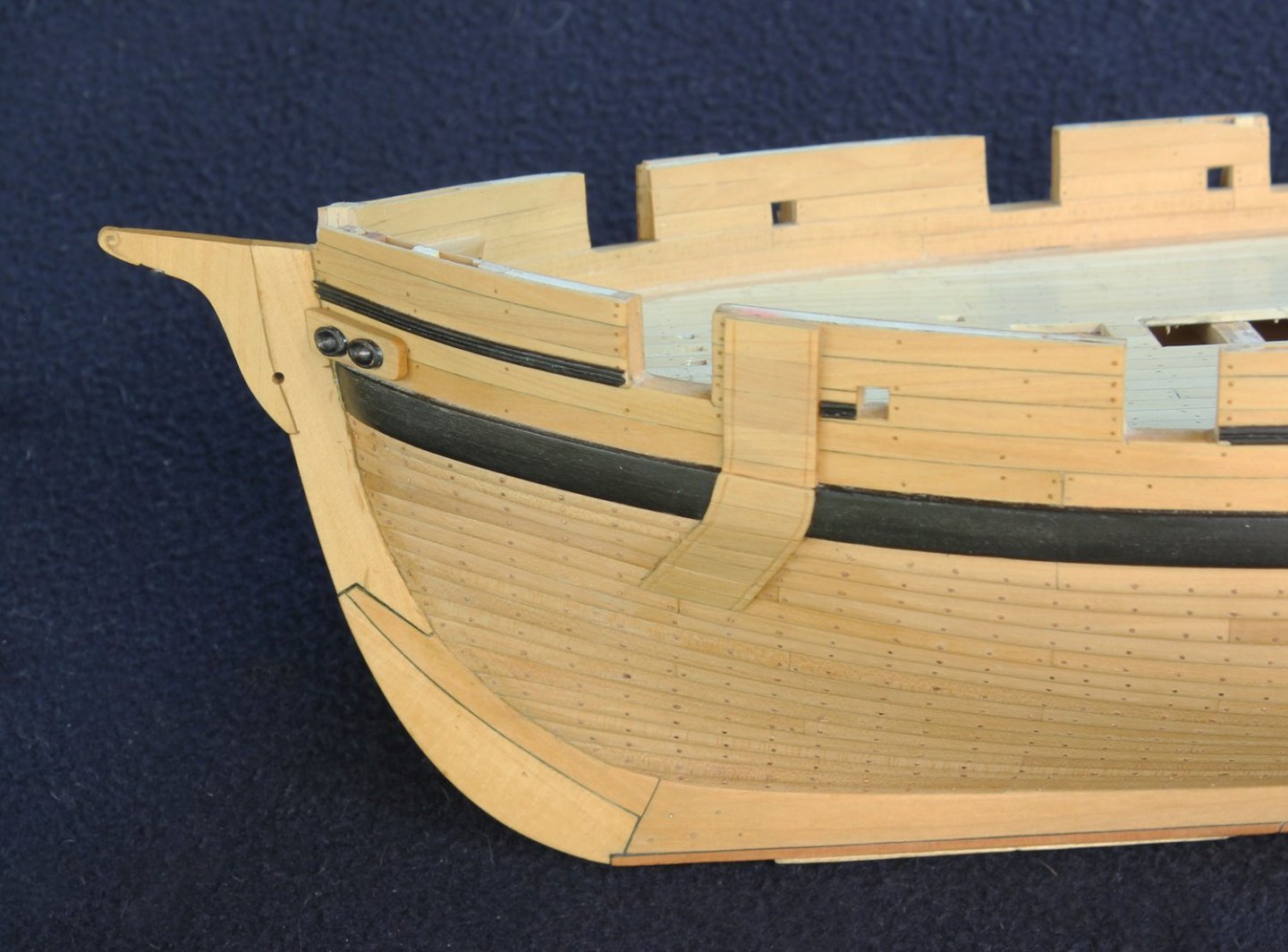
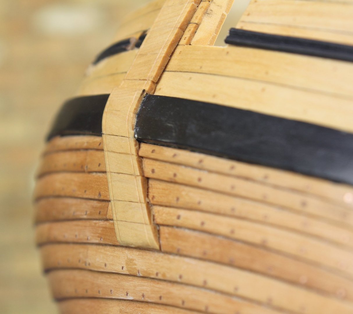

Four scuppers are visible on the model but are not shown on the plan. They were lined with copper tubing blackened in situ with liver of sulfur (LoS). I have also started work on the fashion piece. Although the model shows painted scrolls and gold leaf, my model will be much simpler. I have not decided on its final appearance but most likely will simply paint it black.
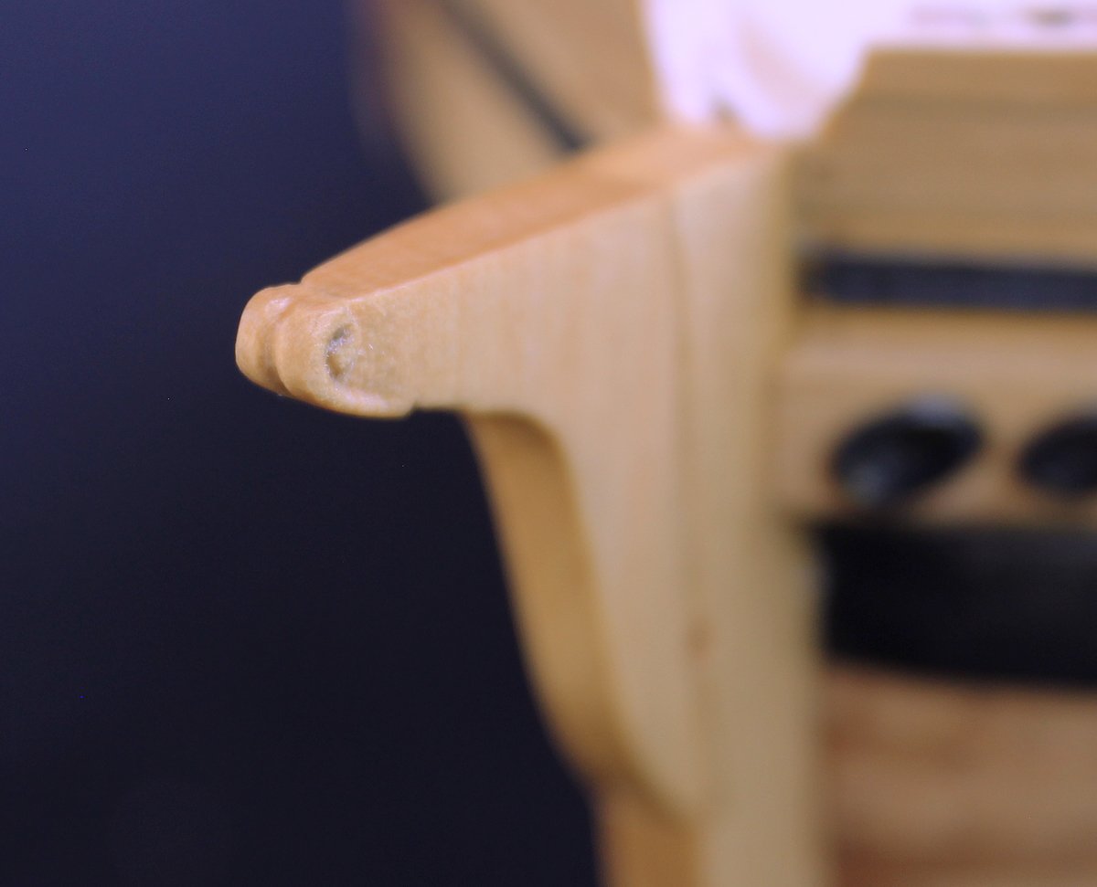
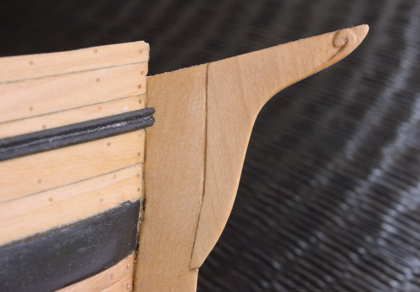
I have refined the top of the stem, narrowing it and incorporating the hances into the tip. As you can see, all the black paint will need touching up.
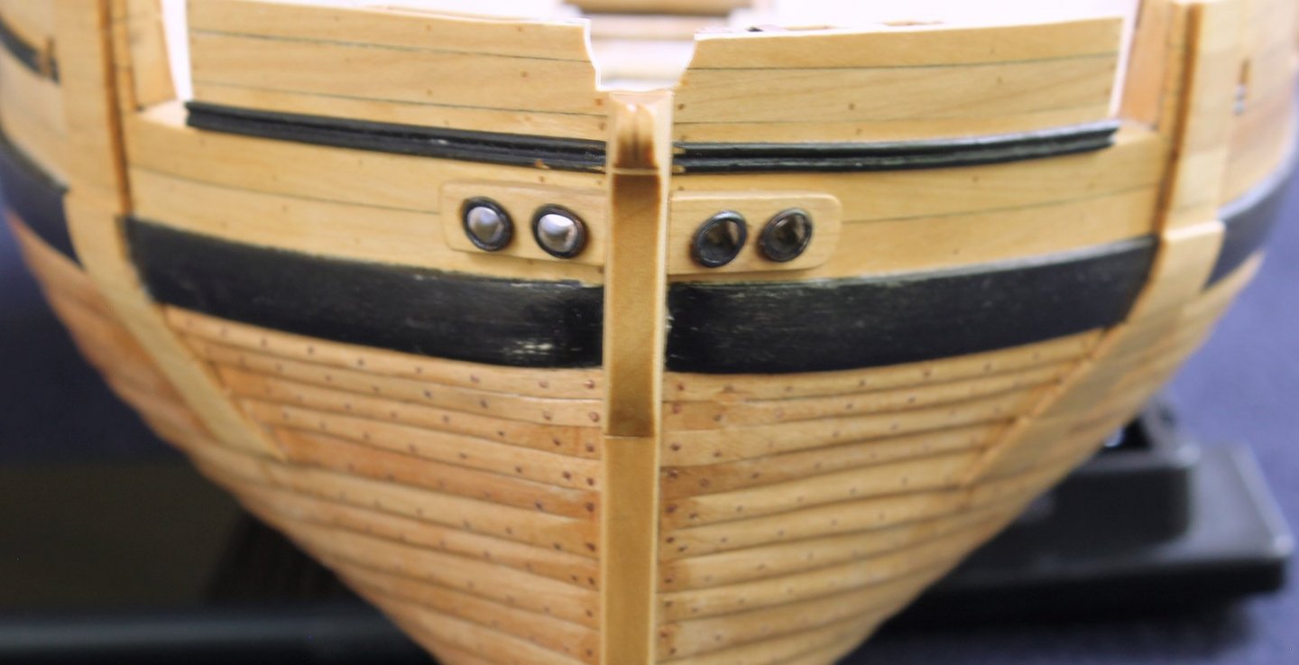
The hawse holes are 10 inches in diameter. These were drilled out and then sanded to their final size. The pipes are copper. After the outboard shape of the pipe was determined, a piece of copper tube one size larger was shaped and soldered onto the end to simulate the rolled edge of the pipe. The inboard profile was then shaped. The hawse pipers were blackened with LoS after all of the excess solder was filed off. LoS will not blacken silver, only copper.
- Kusawa2000, druxey, G.L. and 16 others
-
 19
19
-
Would you like to see your model as a pinup girl next year? We are currently accepting submissions for the 2022 NRG/MSW Calendar. The only requirements are that the file is at least 5MB and that the picture is well composed. It does not need to be an entire ship; a close-up of an interesting feature (like the headworks) or a diorama is also welcome. You do not need to be a member of the NRG to enter.
If you are interested, send me a low resolution photograph via PM. Everyone whose photo is accepted will receive a complementary copy of the calendar.
- Knocklouder, Kusawa2000, mtaylor and 6 others
-
9
-
I would suggest that before you go any further, you look at build logs of other open boats from this era. There are several builds of the Model Expo longboat that will help you understand the construction of your model, since it is very similar. Syren's Medway Longboat is more complex but also provides good background information.
An excellent rule of thumb in kit building is that if the instructions make absolutely no sense, they are probably wrong.
- mtaylor, Ryland Craze and allanyed
-
3
-
-
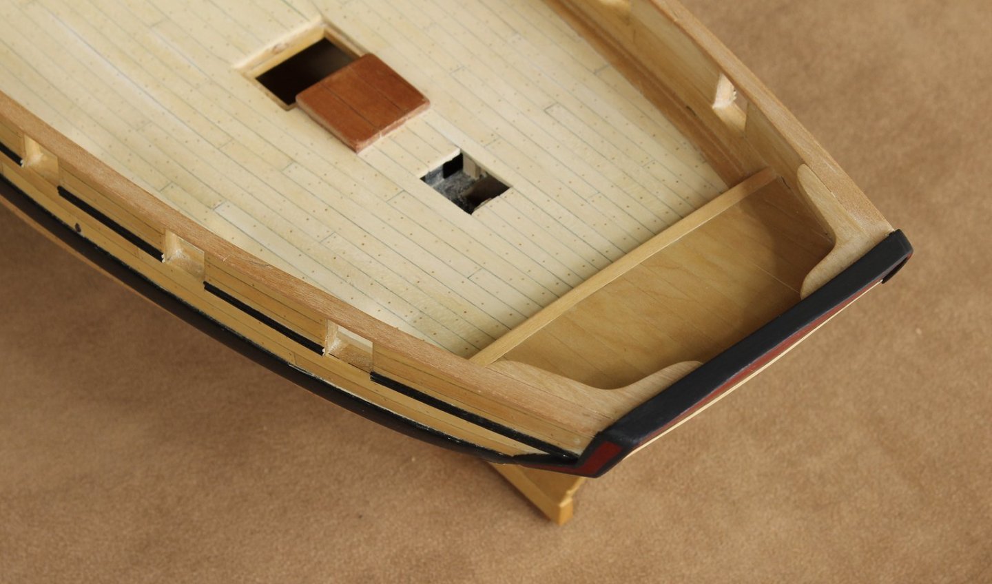
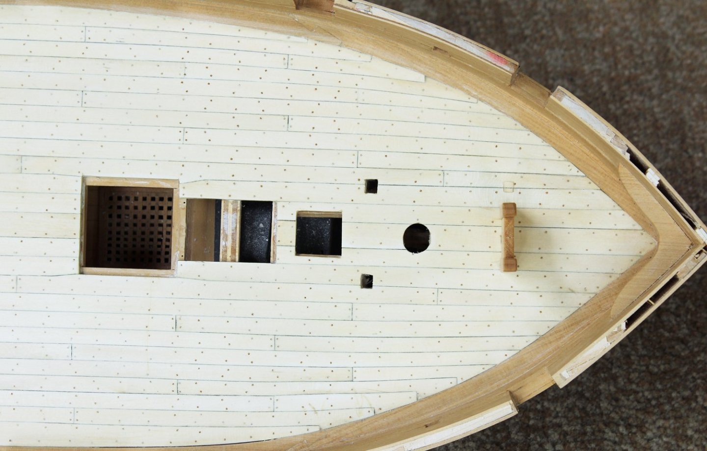
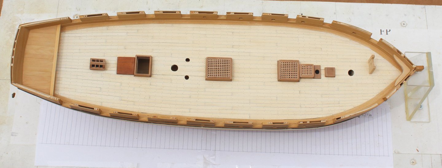
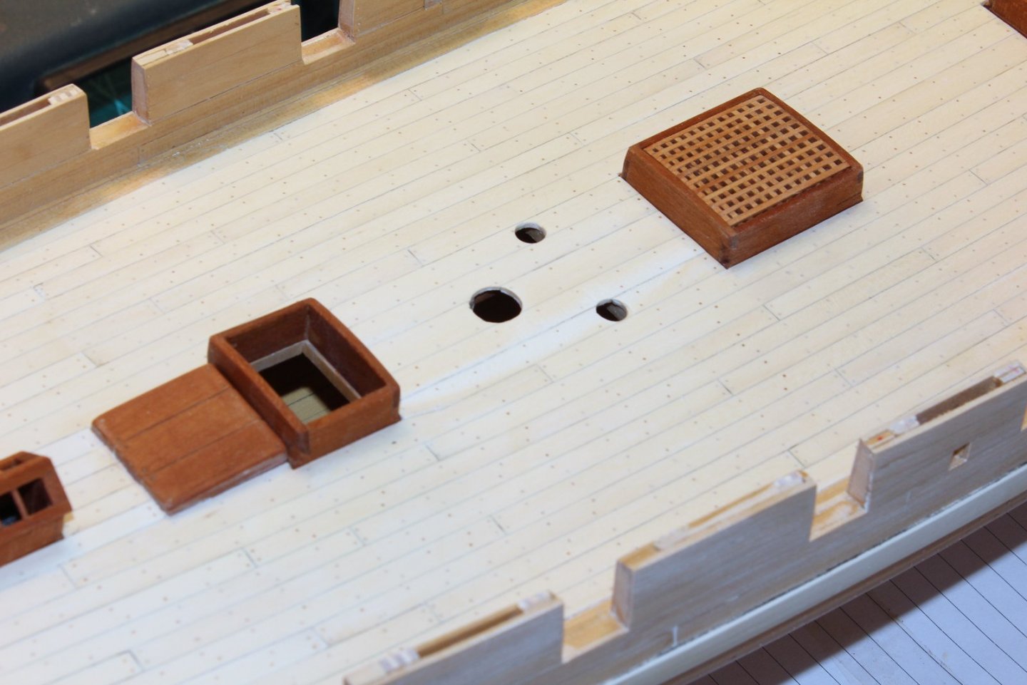
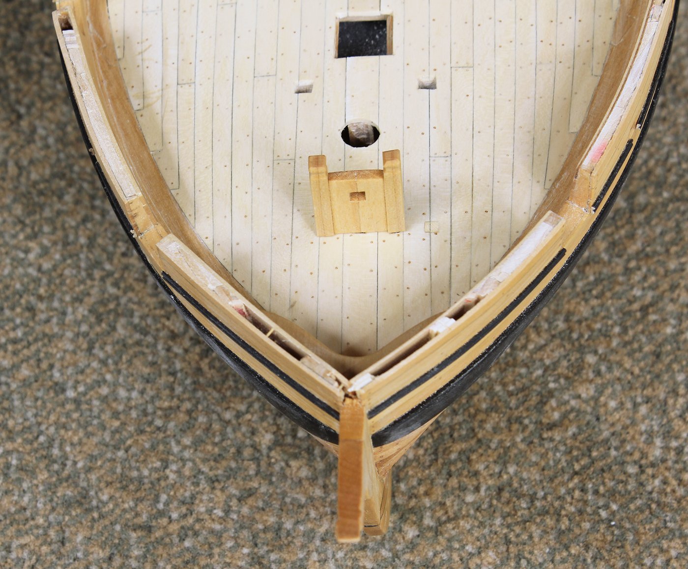
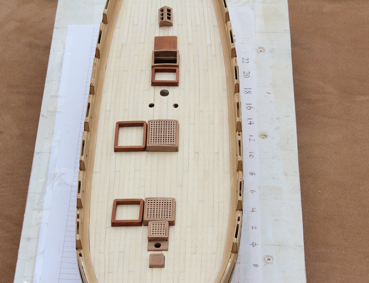
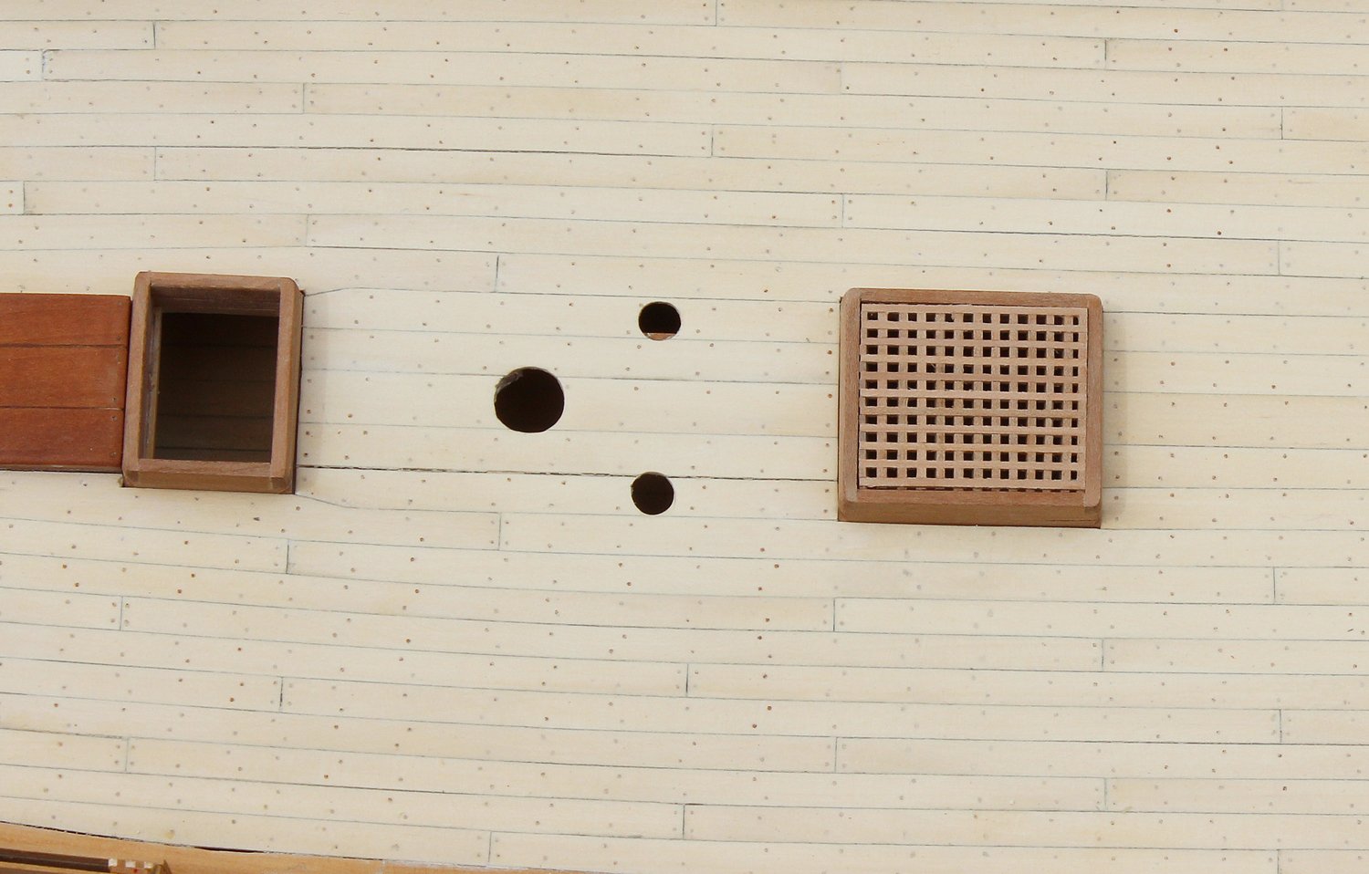
Time for some modeling surgery. In order to position the bowsprit in the midline, the step needs to be moved. The holes were already made in the deck for the step. One of the holes will be hidden by the center part of the step but the port side one needed to be repaired. My options were: remove and replace the two deck planks where the hole passed or make a plug and insert it in the hole. My concern was that I would probably do more damage to the surrounding planks and waterway by doing so. Look at the June 5th post to see that these were not typical planks. I opted for a plug. The repair is not perfect, but I believe this was the more prudent approach.
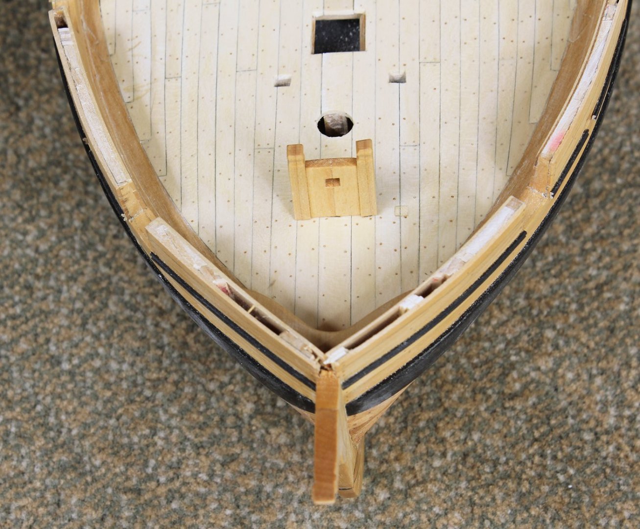
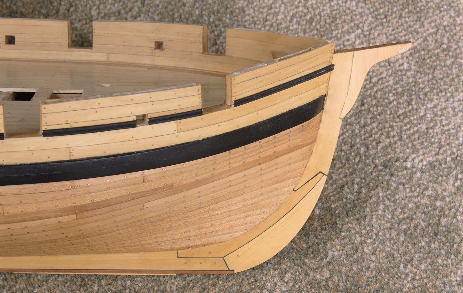
Next, the stem head was installed. This has a shallow mortise at its foot into the stem. A small scroll is carved at the fore end.


- rlb, giampieroricci, Gregory and 12 others
-
15
-
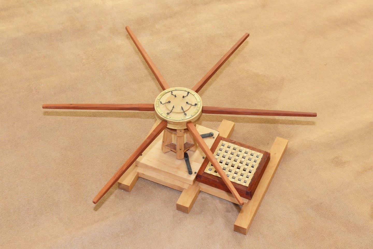
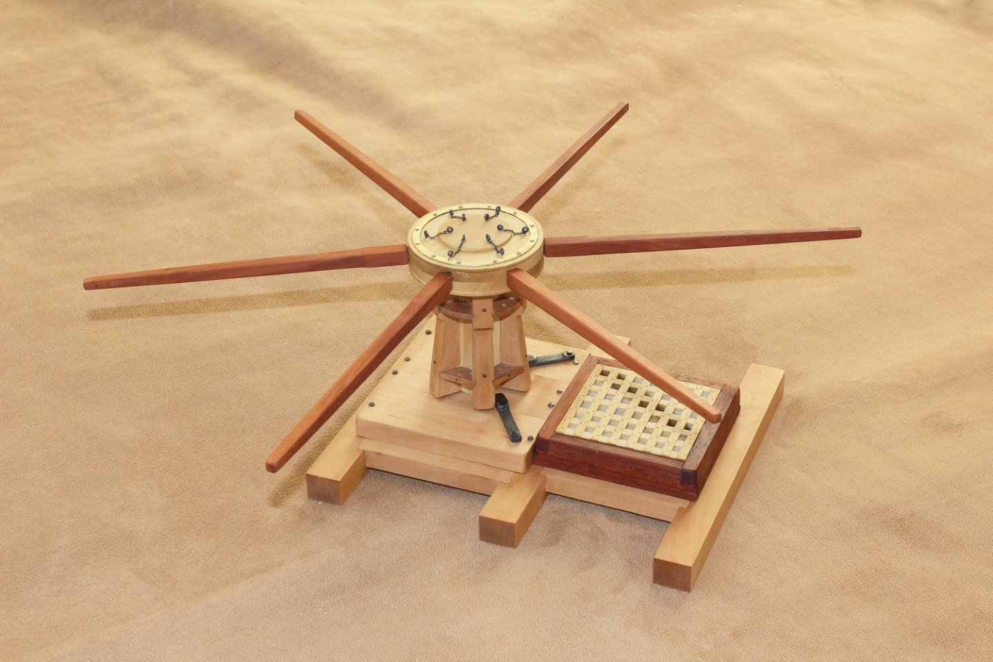
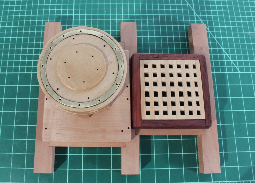
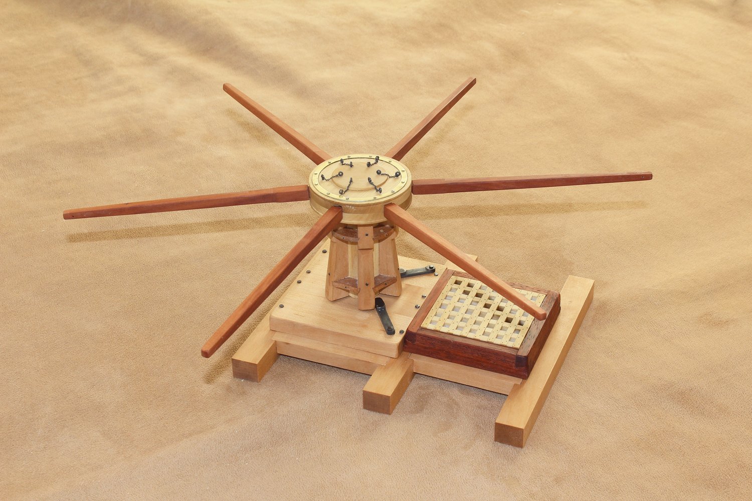
All that is left to make is the capstan bars and brakes. This was shown in the intermediate version and will not be repeated.
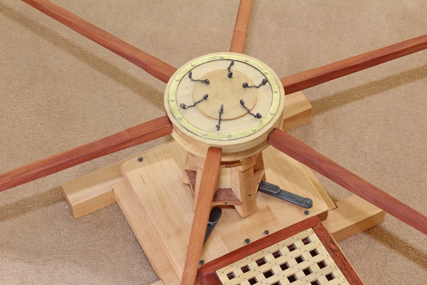
Time to put everything together. This was a fun project to design and build. It does not take a long time to build and it makes a handsome desk ornament without the bars or in a display case with the bars installed. The project is available for purchase in the NRG store at https://thenrgstore.org/collections/plans-and-projects/products/capstan-project. It contains separate plans and monographs for the intermediate and advanced versions.
-
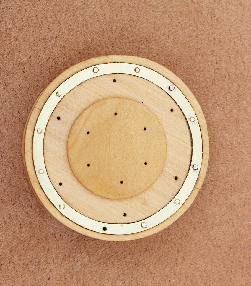
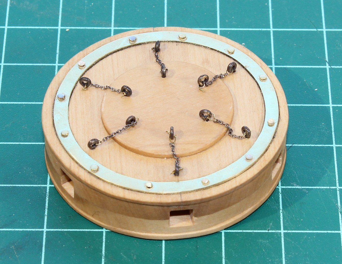
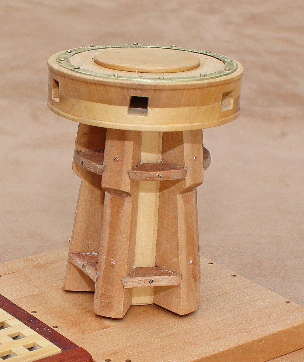
An alternate approach would be to use brass instead of wood to represent the iron ring. The bolts are brass nails with their heads filed flat. The holes for the capstan bar pins have been drilled.
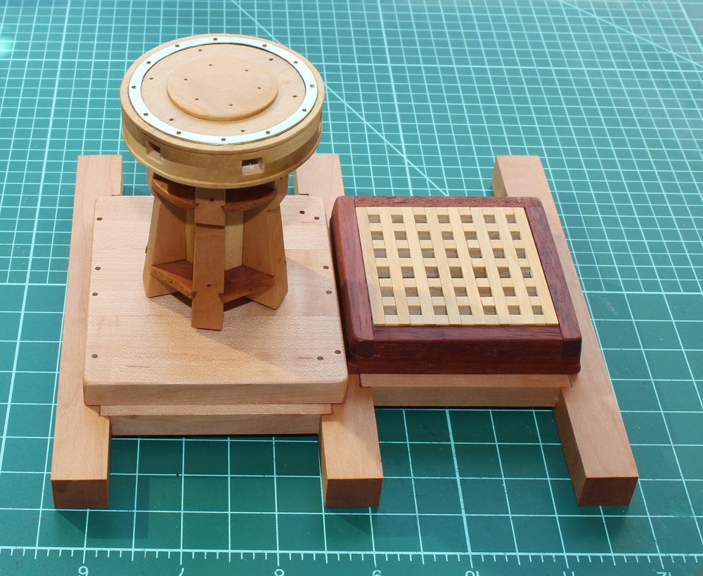
After a coat of finish, the capstan is trial fit on the step. Compare the appearance of the step and capstan in the next two pictures, showing the effect of a coat of Watco's. I used copper wire for the whelp bolts and they have not been blackened yet. This will be done with liver of sulfur.
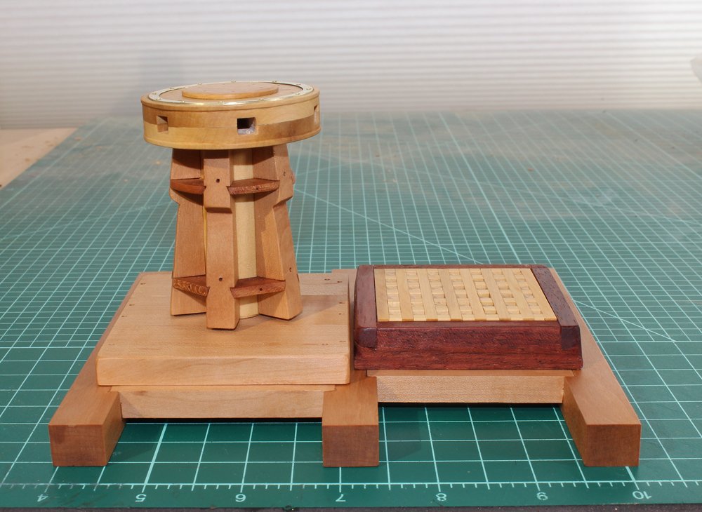
The eyebolts and capstan bar pins have been installed. Make sure the chain is long enough to allow removal of the pin.
- Canute, popash42, GrandpaPhil and 6 others
-
9
-
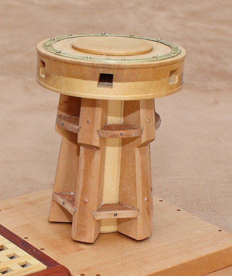
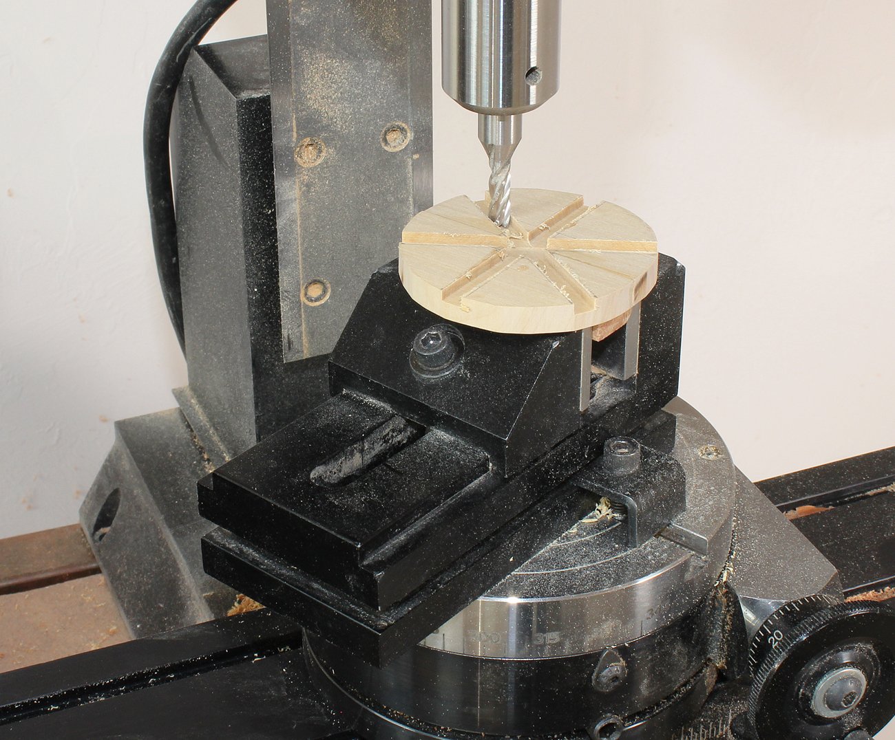
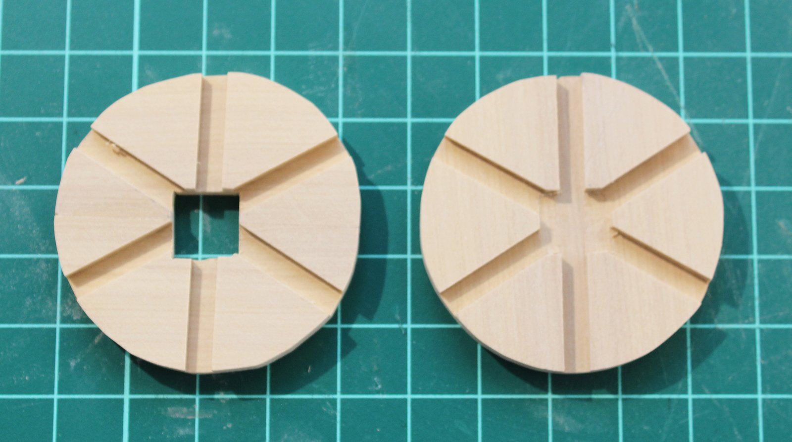
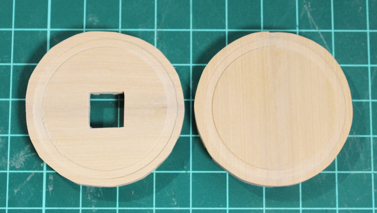
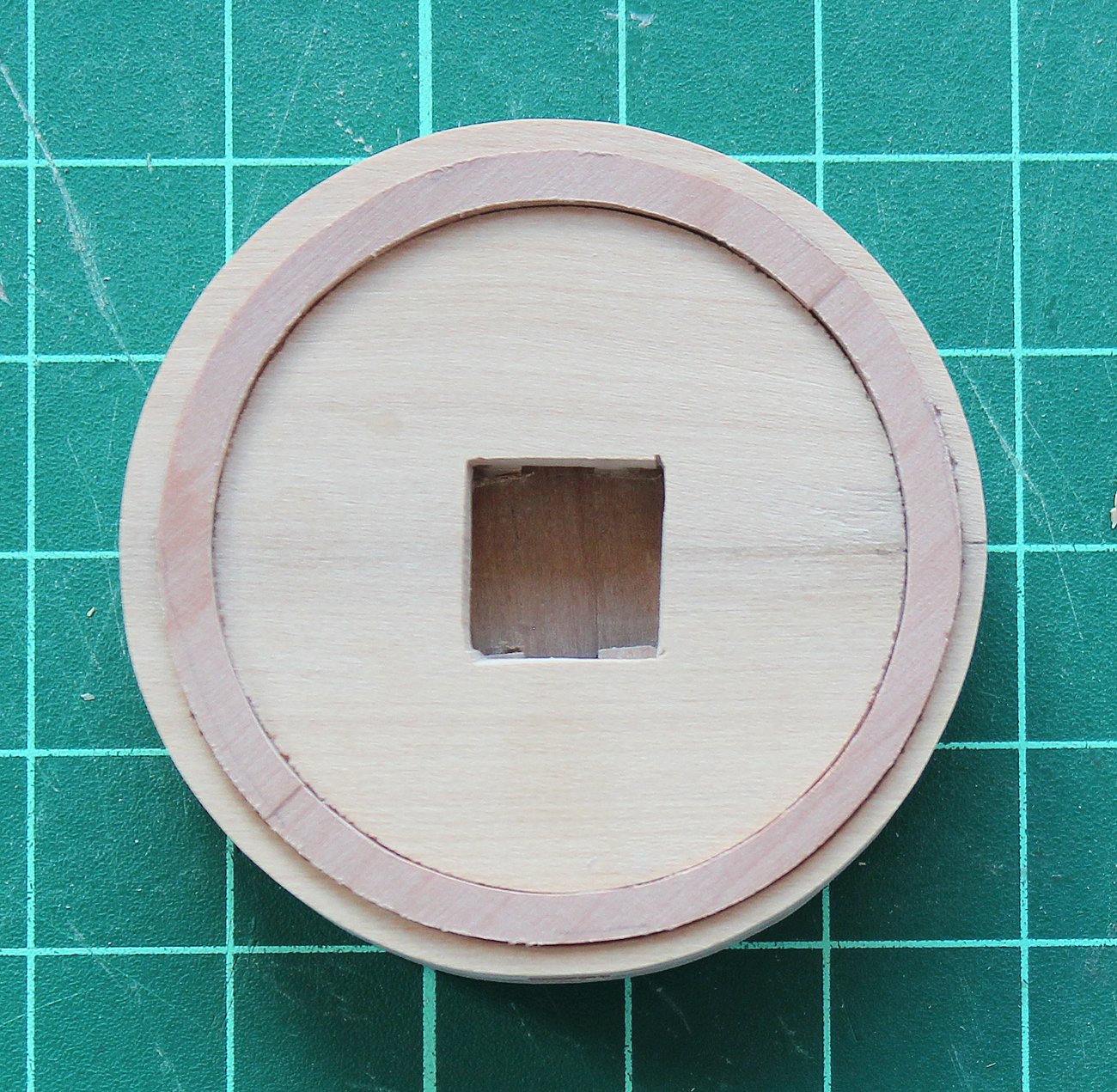
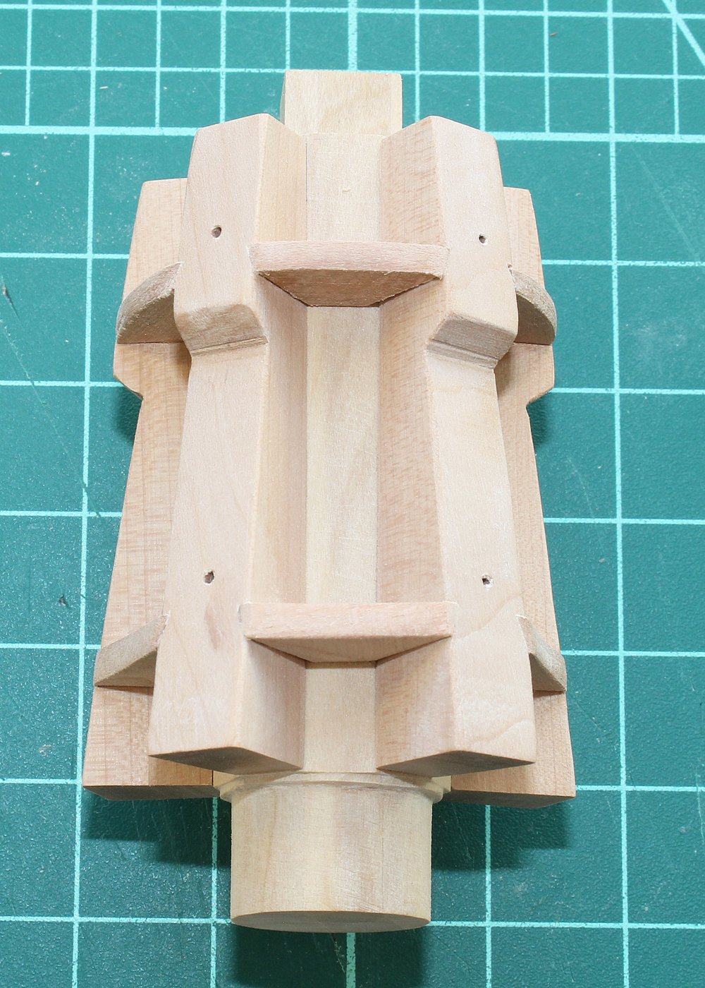
The barrel is complete except for bolts in the whelps and chocks. Just like in the intermediate project, the drumhead is made up of seven major pieces, two upper and two lower drumhead halves, two iron rings and the cap. There are also several miscellaneous bolts and fittings. After the two drumhead halves have been glued up and shaped (see the posts in the intermediate project), they are each glued to a block of wood. This block of wood secures the drumhead to the mill vice so that the recess for the iron ring can be milled. Do this on both the upper and lower drumhead parts.

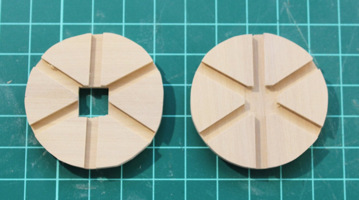
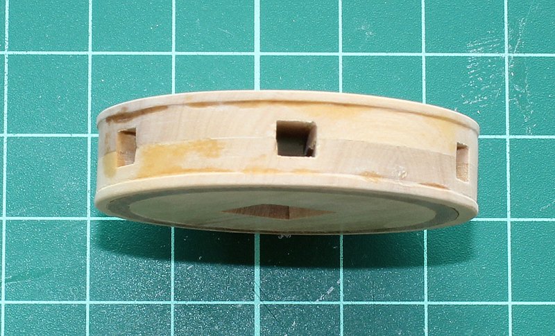
Debond the block of wood and glue it onto the other side of the drumhead to mill the slots for the capstan bars. The lower drumhead has a square opening for the top of the barrel.
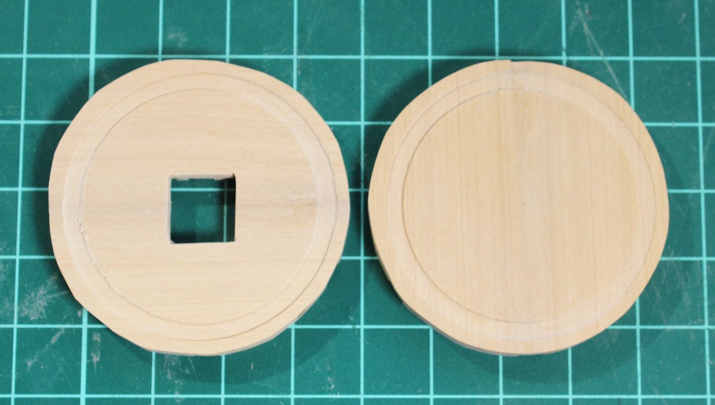
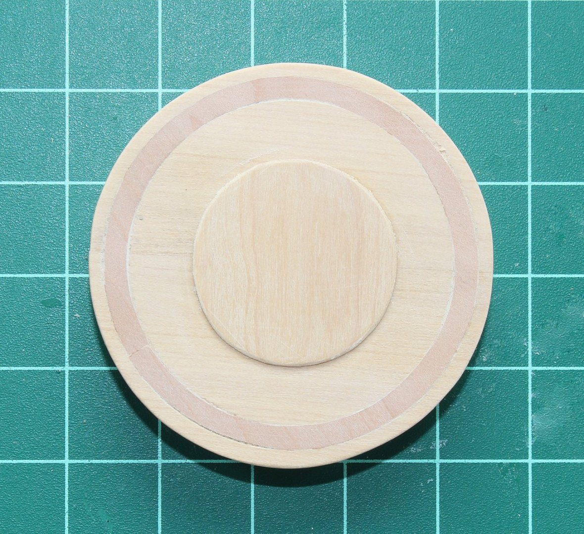
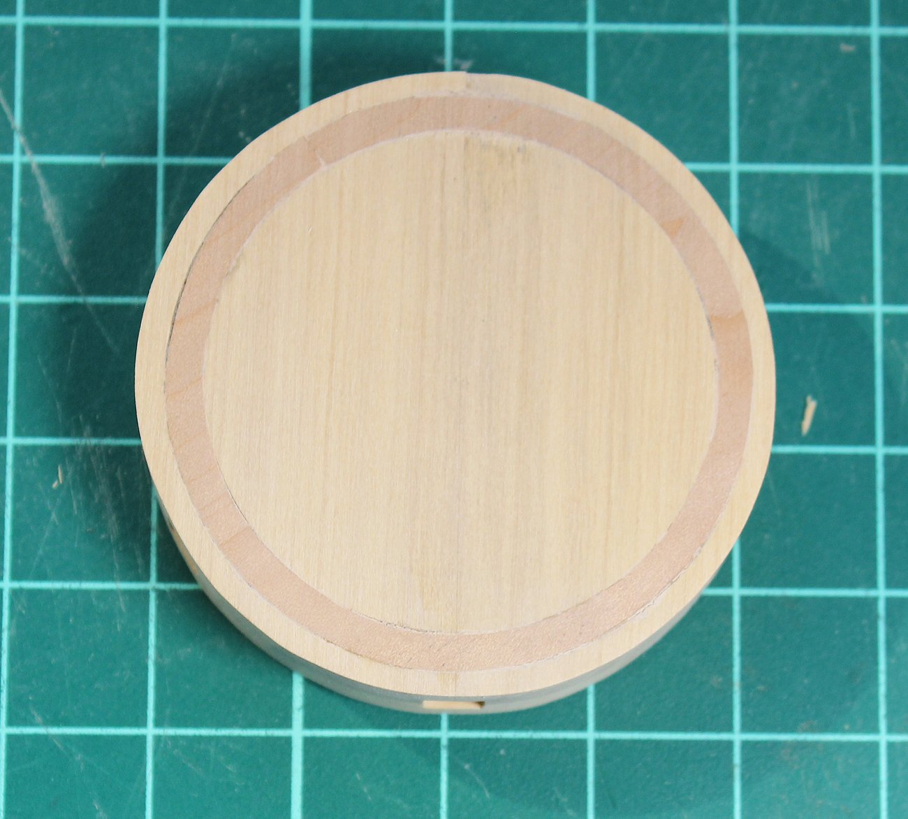
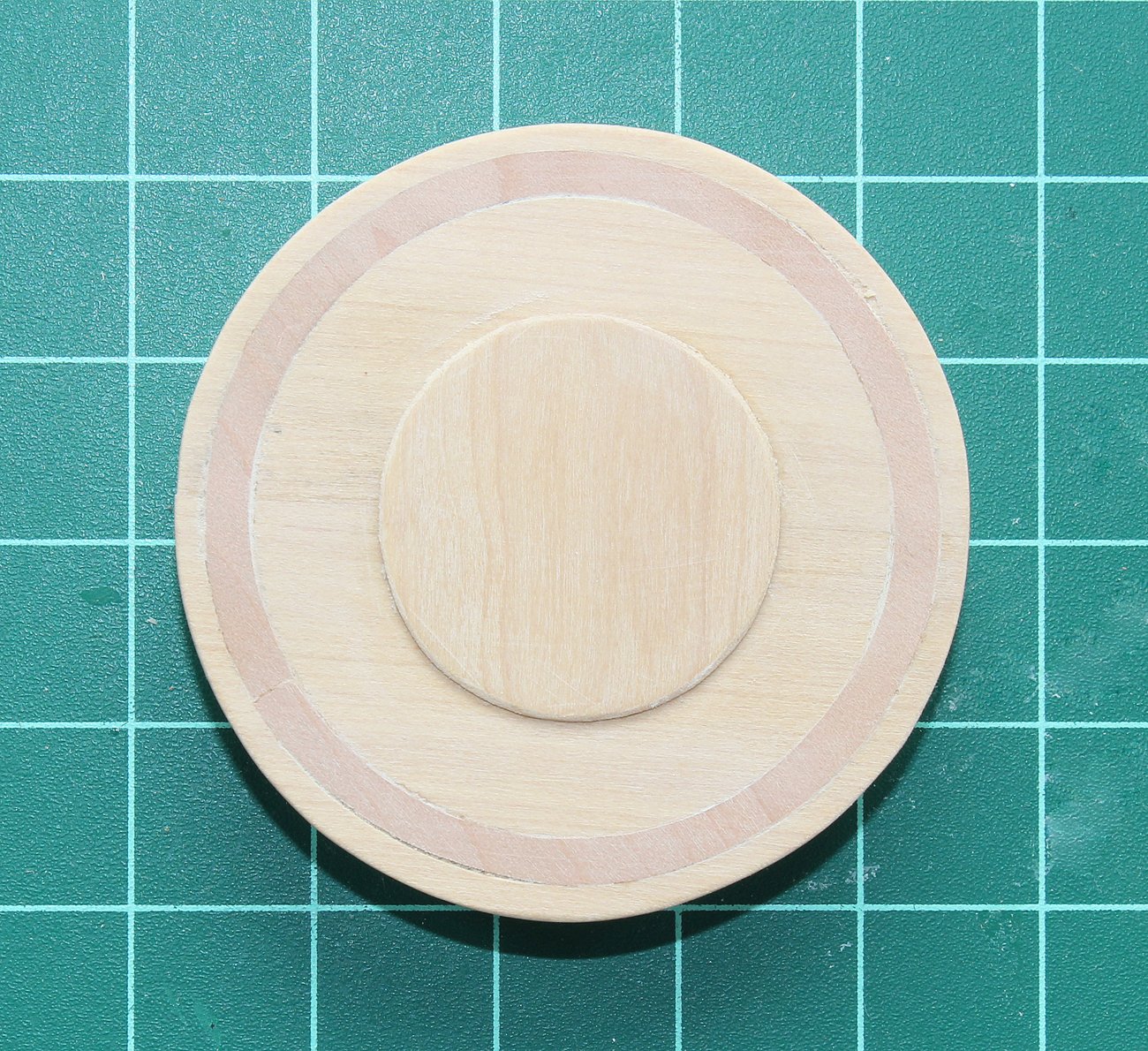
The iron ring is next. I made mine from contrasting wood, in this case pear. They are difficult to cut out without breaking because they are very thin and require cutting across the grain. I cut mine with a jeweler's saw. I made the rings thicker than necessary and sanded them flush to the drumhead. The cap was
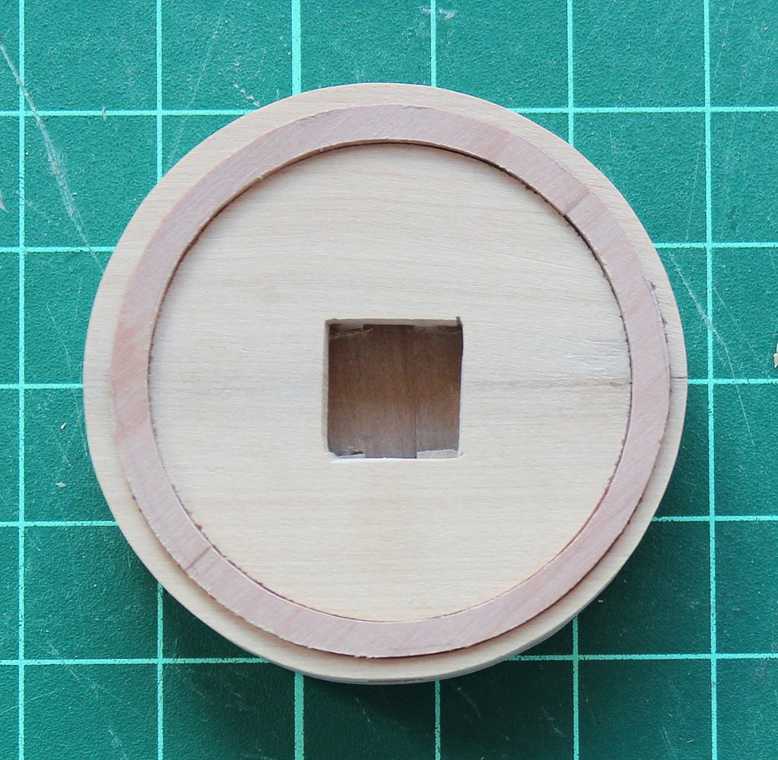

A block of wood was inserted through the square opening in the drumhead bottom. This was then clamped into the mill vise and the side recess was milled. I started in the middle and slowly worked my way out to prevent tear-out. The last bit was finished by hand with files and an 11 blade for the same reason. Finally the cap was glued in place.
-
-
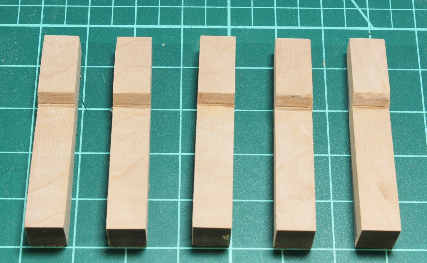
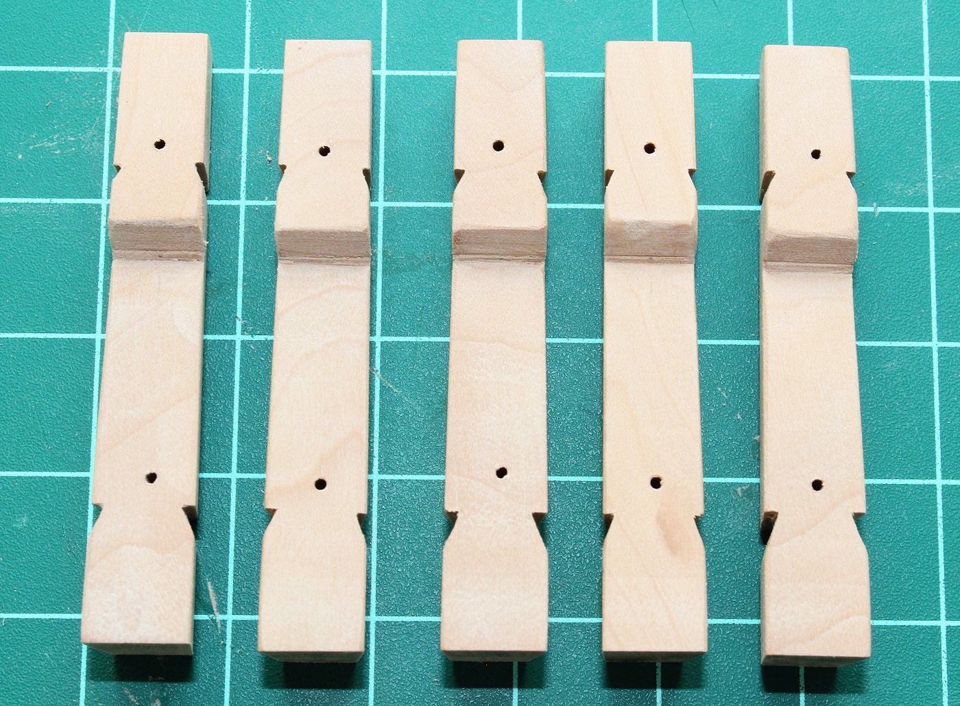
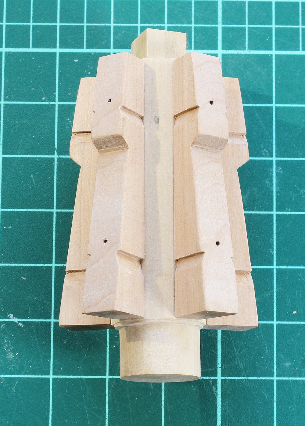
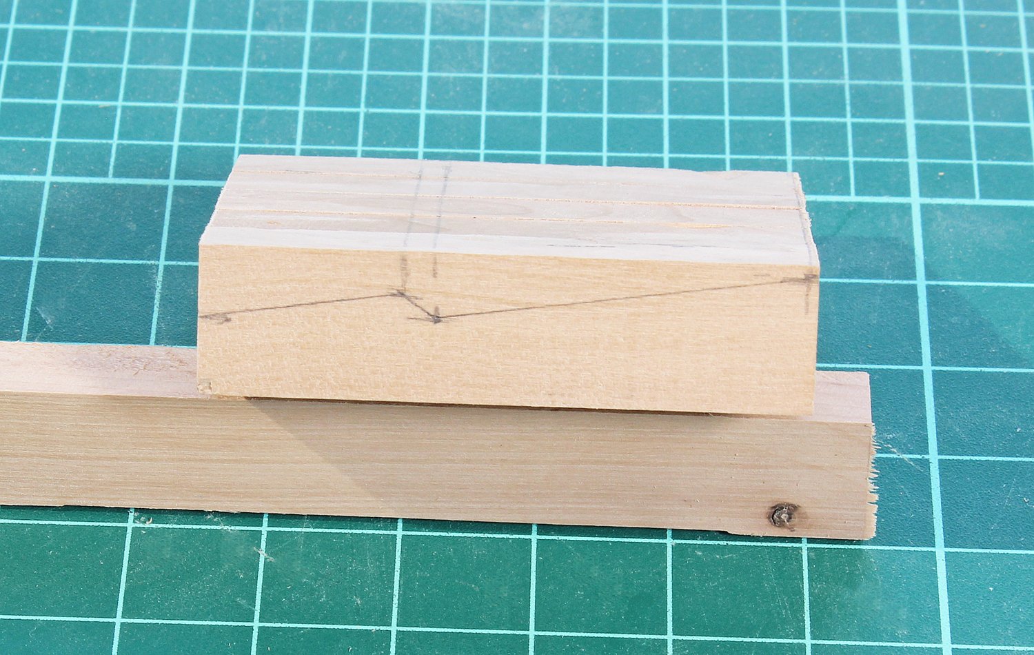
There are five whelps. Their sides flare out top to bottom and from the spindle outwards. The outer face is cut first and then sides are tapered. I made a sandwich of the five whelp blanks (and a few extras) and drew the outer face of the whelp onto the sandwich. There is a little extra wood at the top and bottom to compensate for any chipping from the mill.

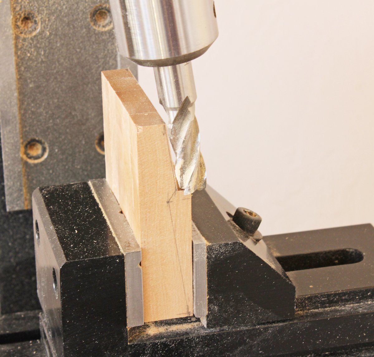
The outer face was milled in three steps, rotating the mill head to obtain the correct angle. The key is to only remove a little wood with each pass.

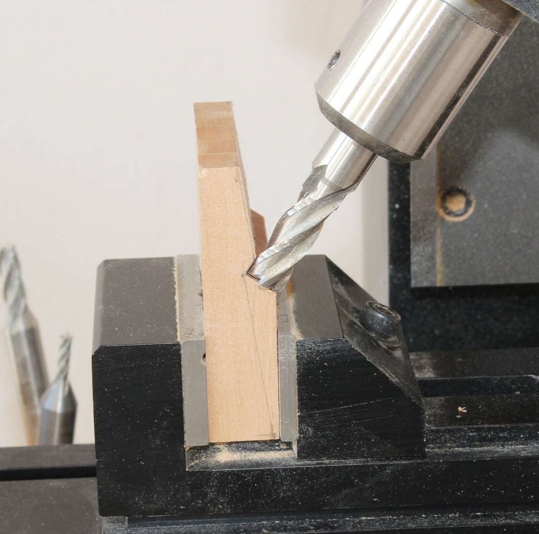
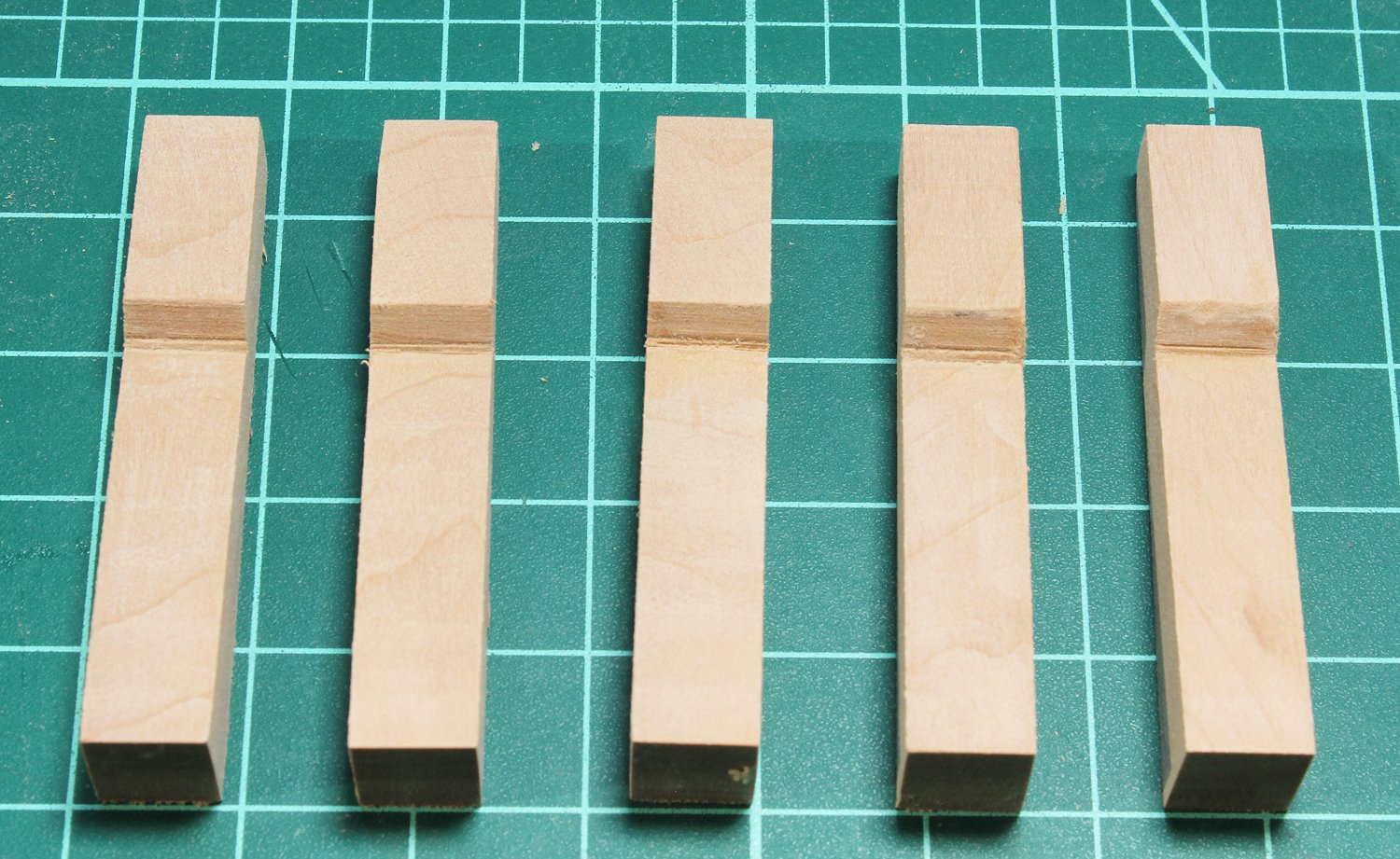
The sandwich is separated into individual whelps by soaking it in isopropanol. The taper was formed on the disc sander and the bolt holes were drilled.
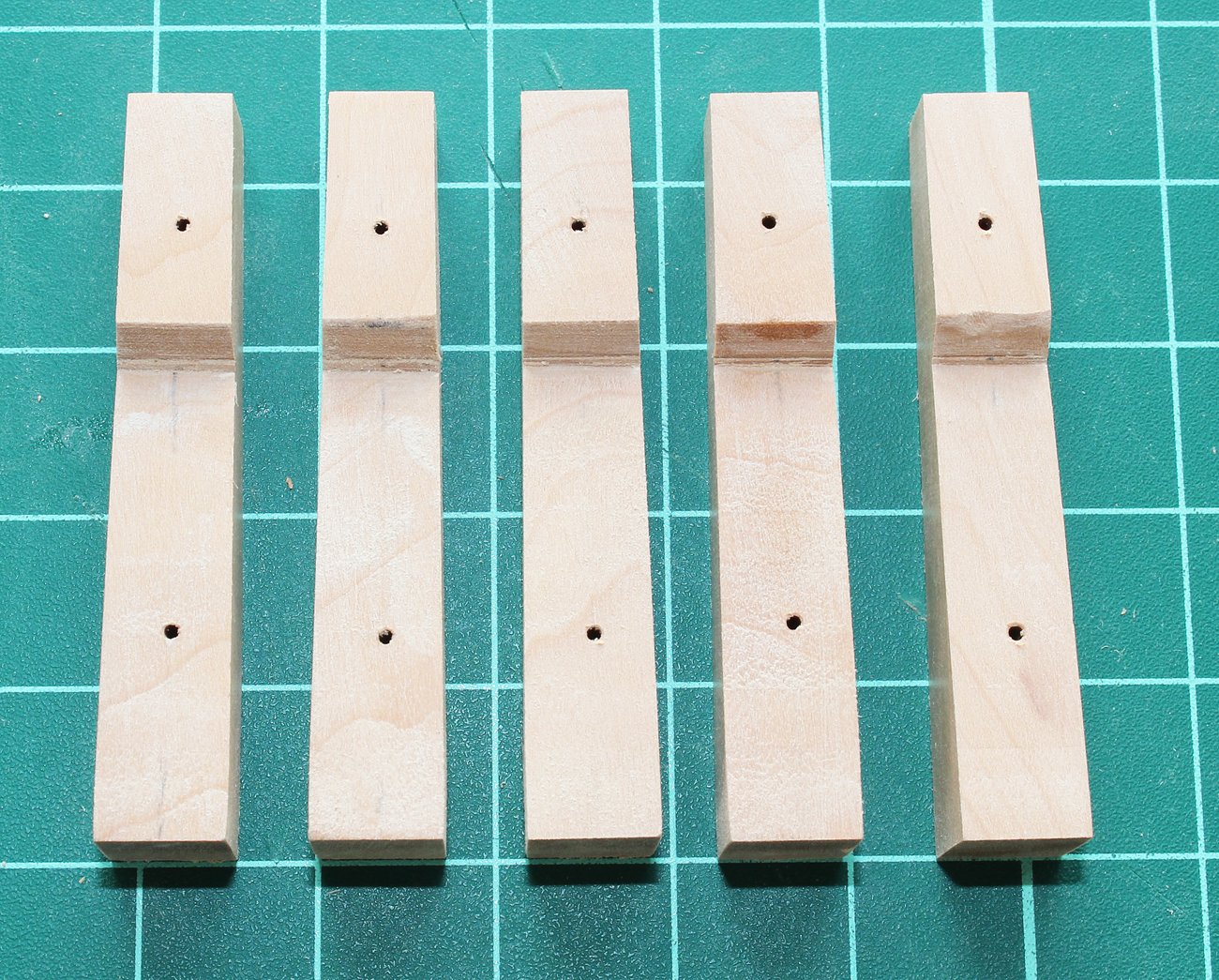
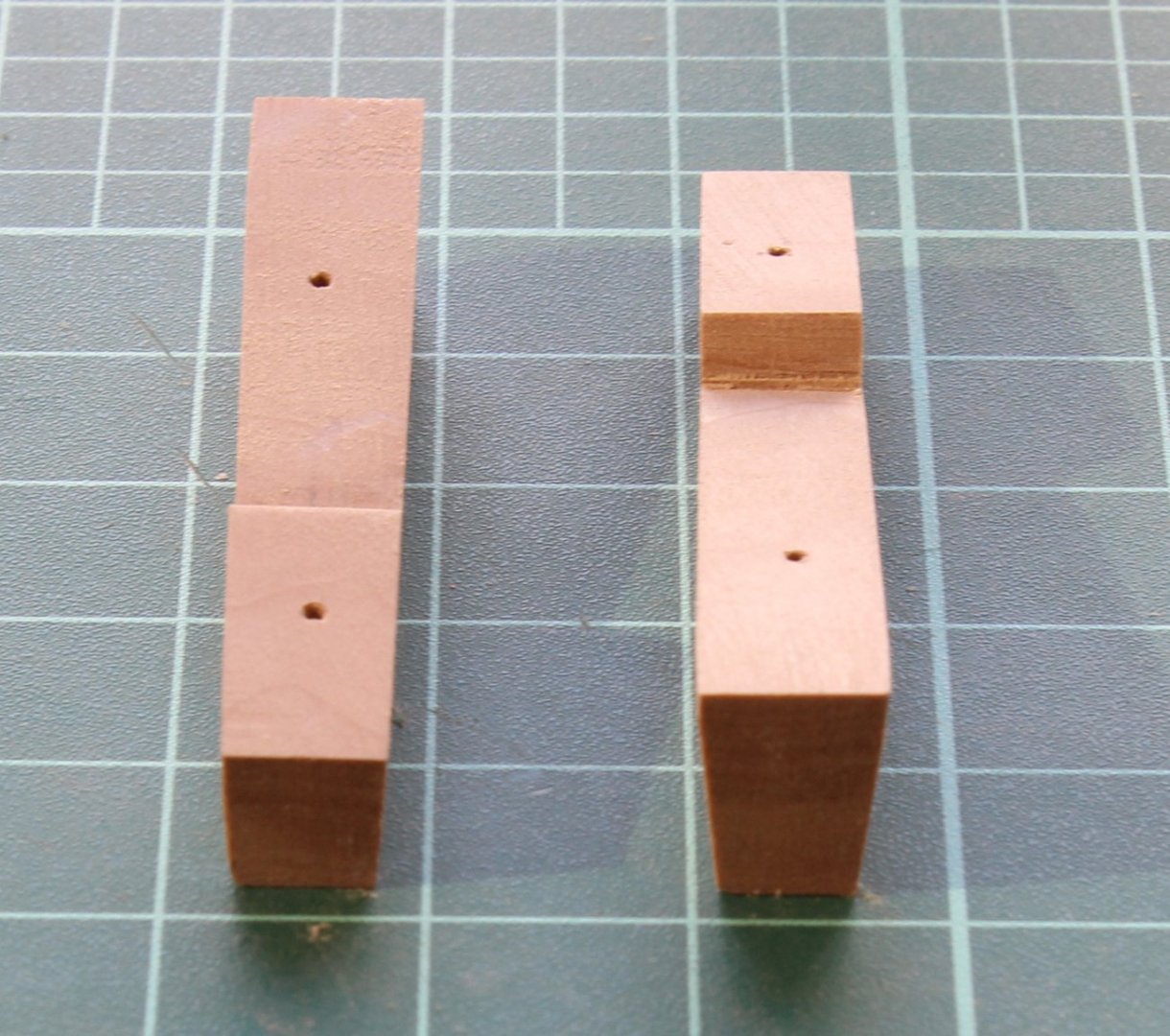
The final step was to cut the slots for the chocks. I used a razor saw and chisels to form them.
-
Looking good, Dan. I would like to make one comment, as this project is a teaching aid for planking. Look at your broad strake at stations 4 and 5. It is a little too wide, resulting in the "waist" at station 4 in your first strake. Generally, if you see an unusual shape in a plank, something is amiss in the adjacent row.
-
-
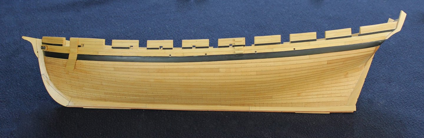
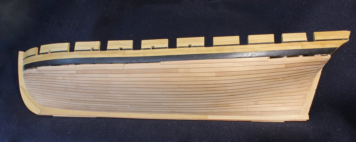
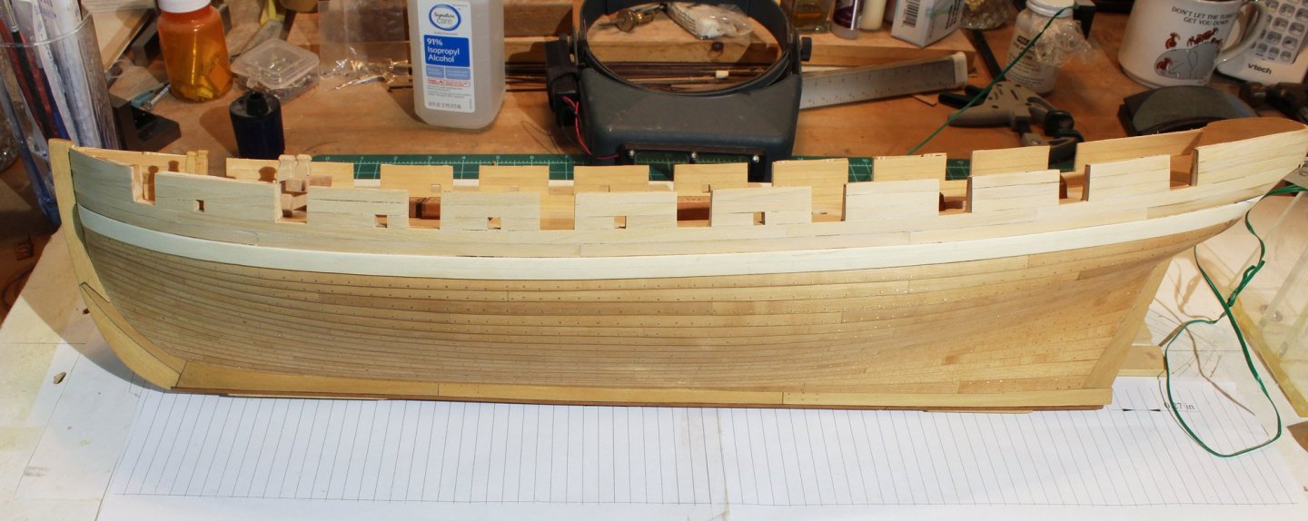
Thanks for the comments and the likes. The wale has been painted and the decorative strip applied. The wale has five coats of very dilute artist's acrylic paint. The strip was painted before installing on the hull. The steps were installed next. They are not shown on the plan so I placed them where they are located on the model. The profile of the step was made with a scraper and the ends were shaped with files and sandpaper. The step overlying the wale will be painted black. Sorry for the sawdust between the steps.
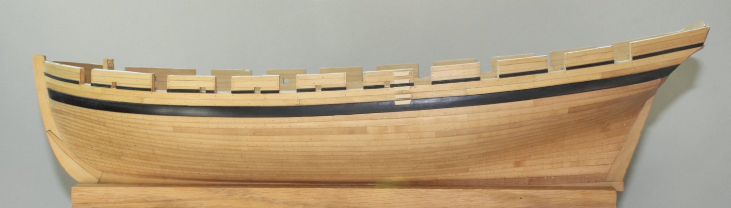
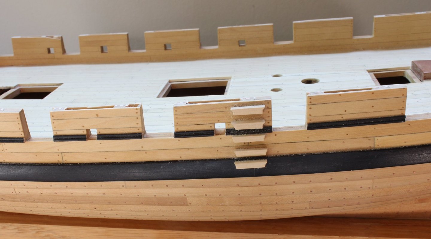
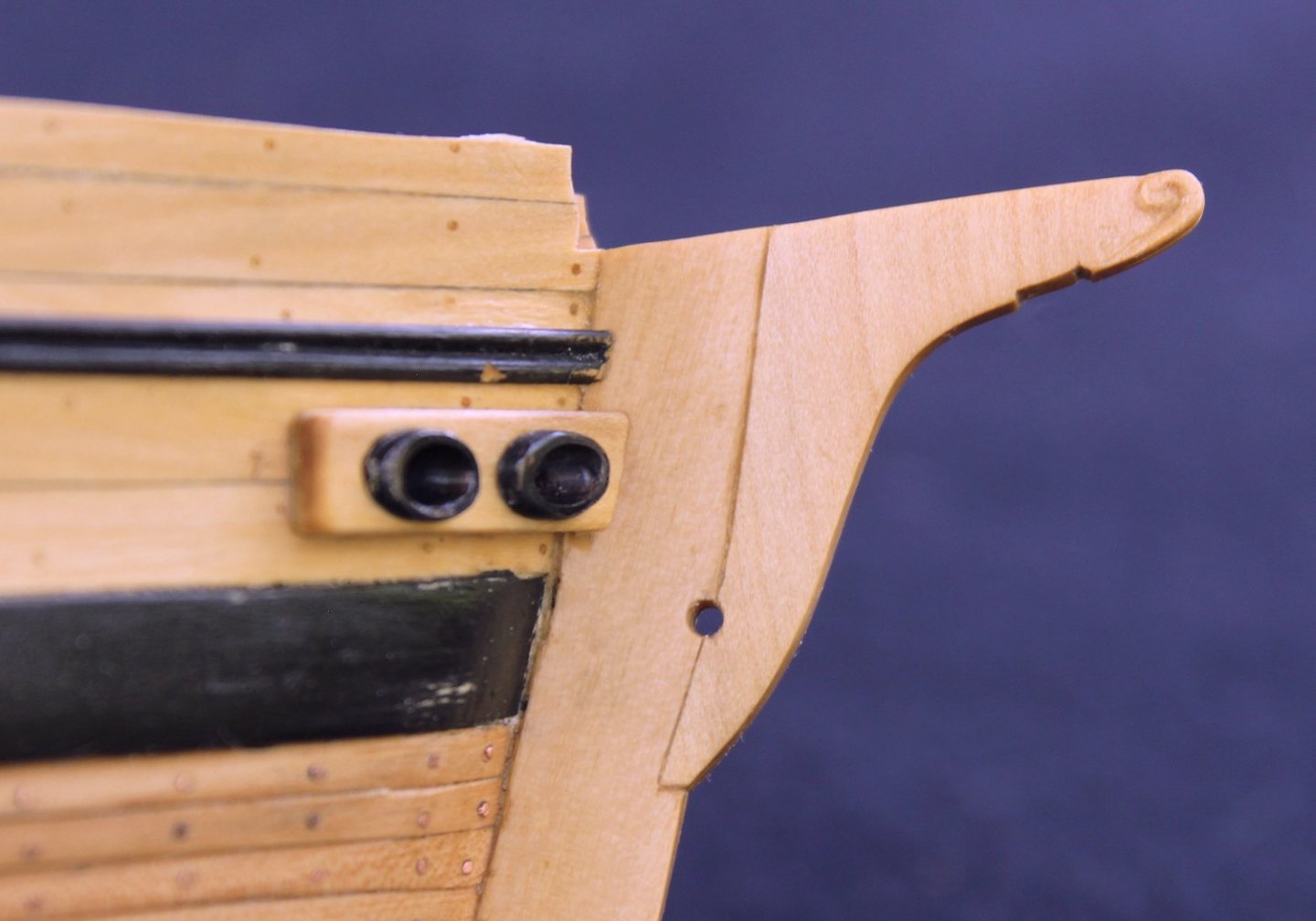
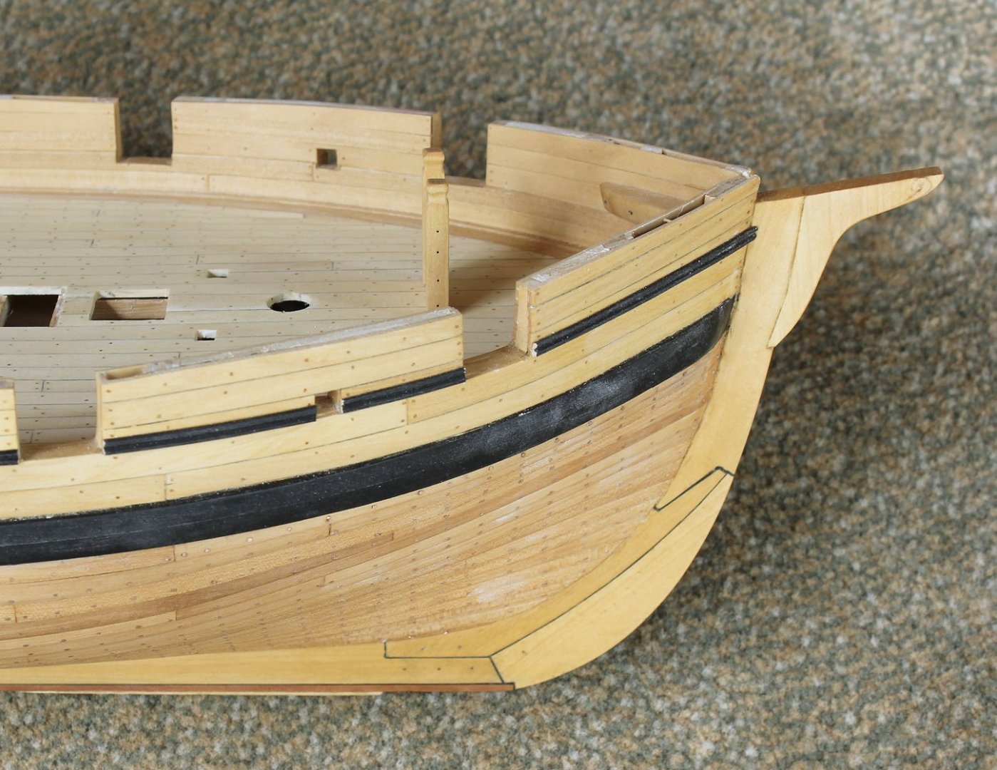
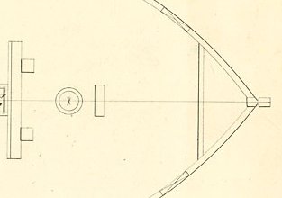
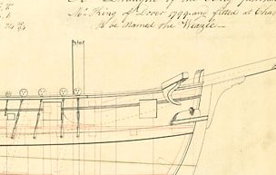
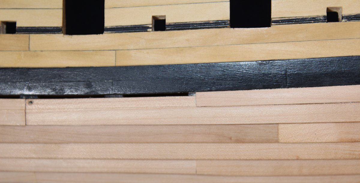
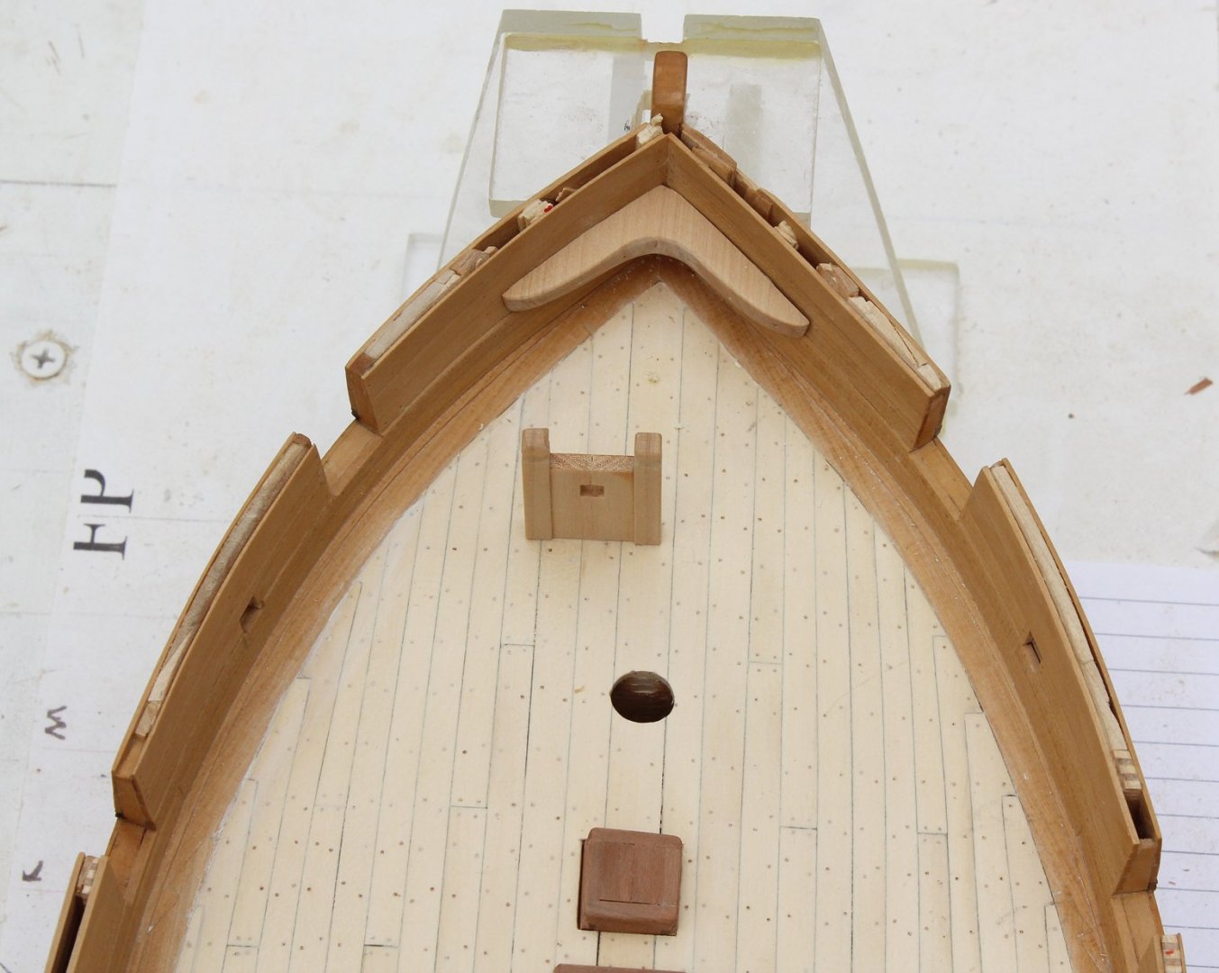
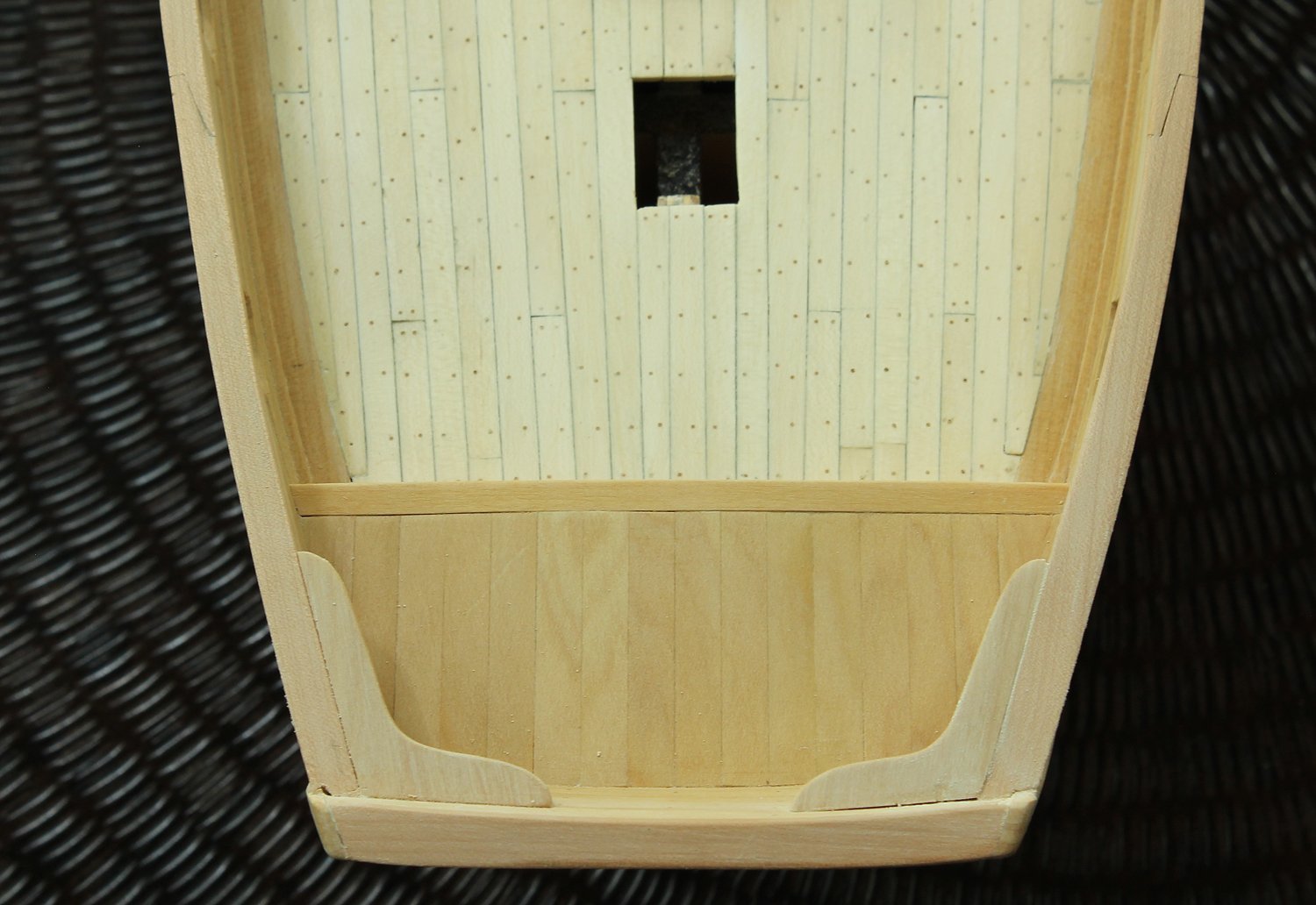
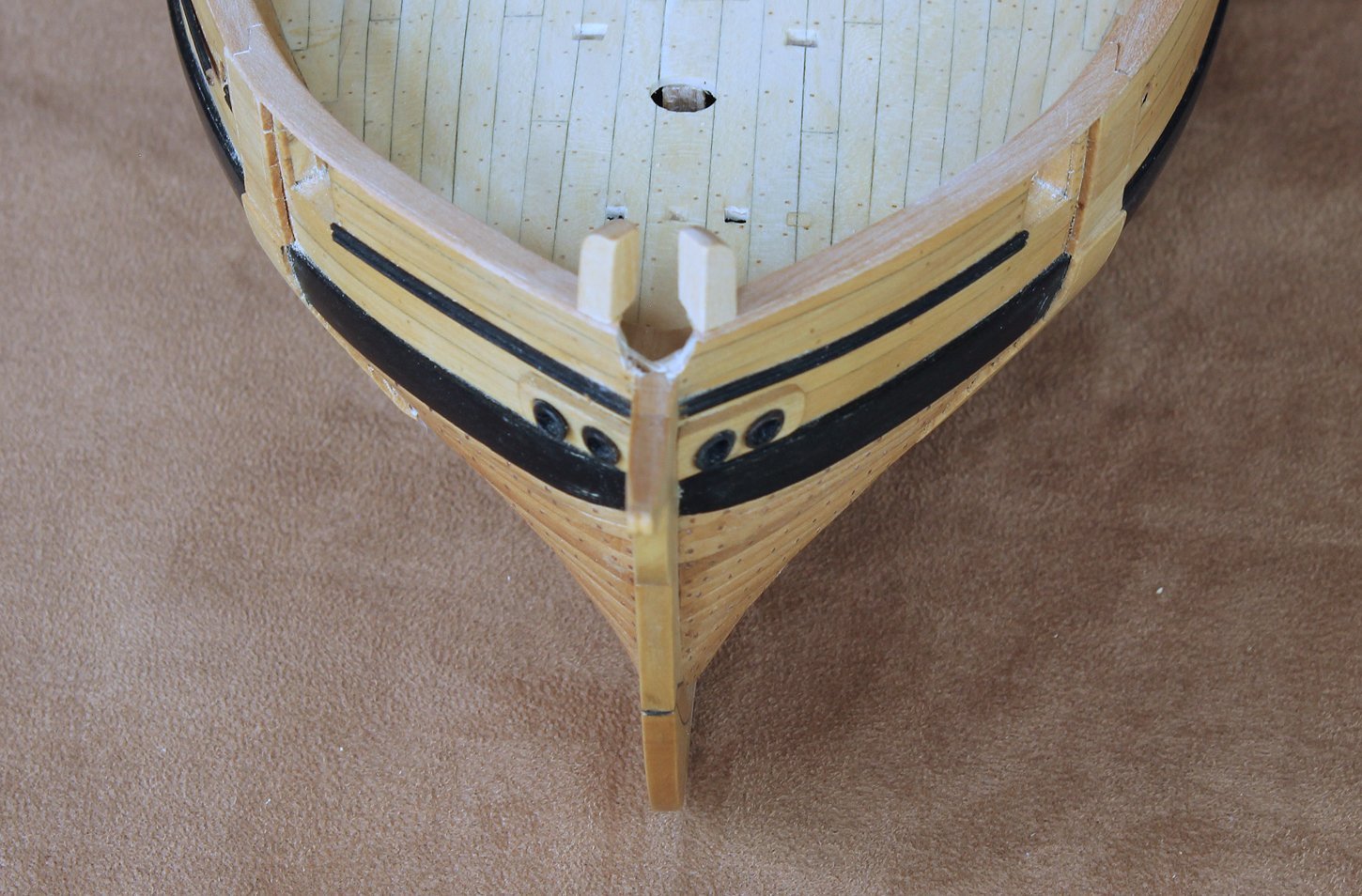
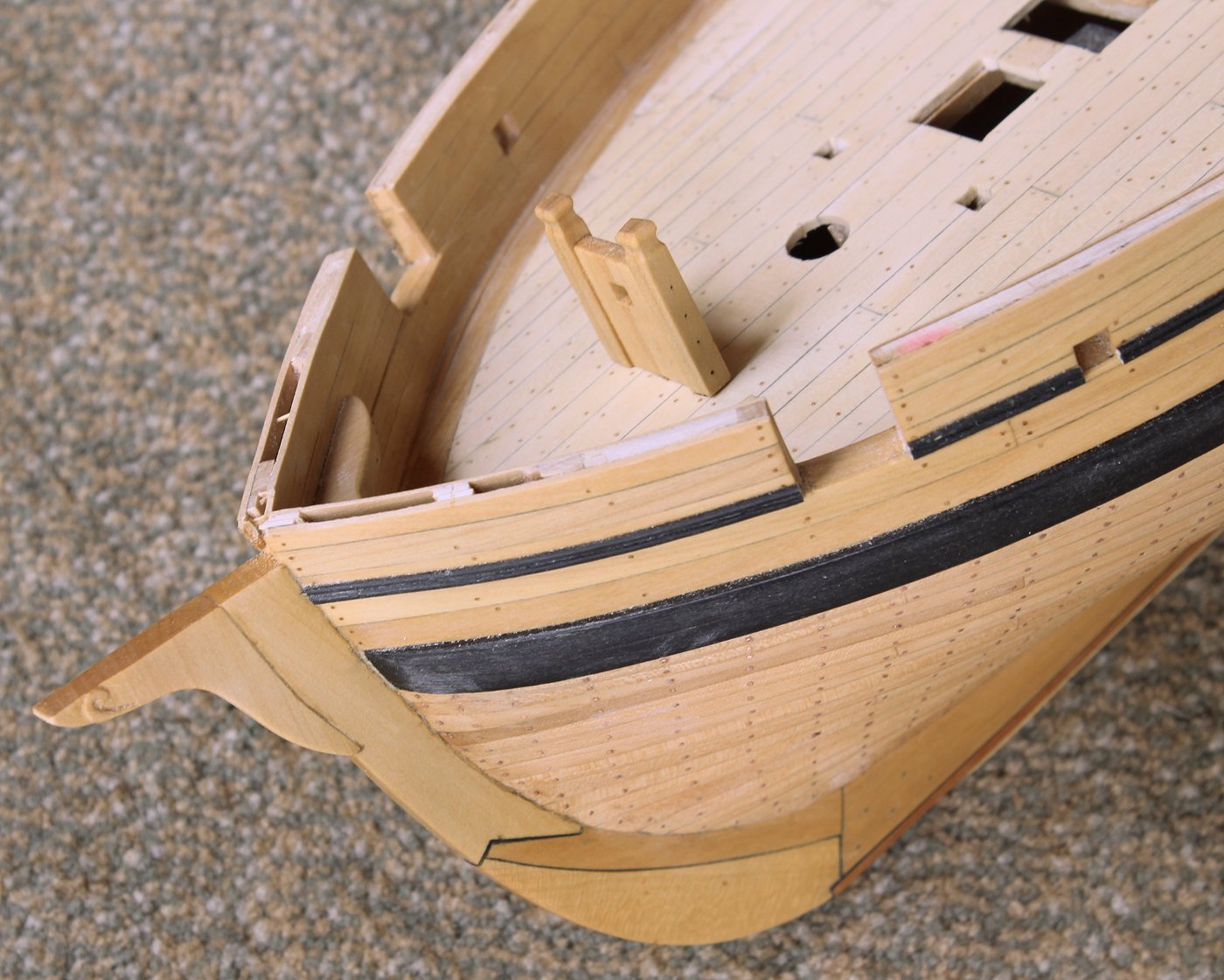
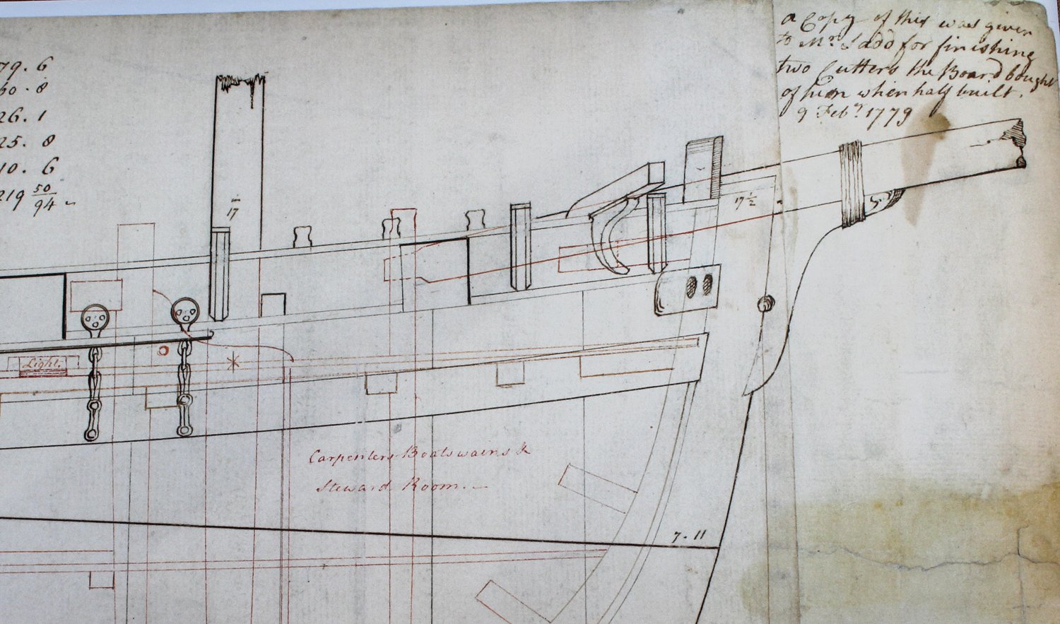
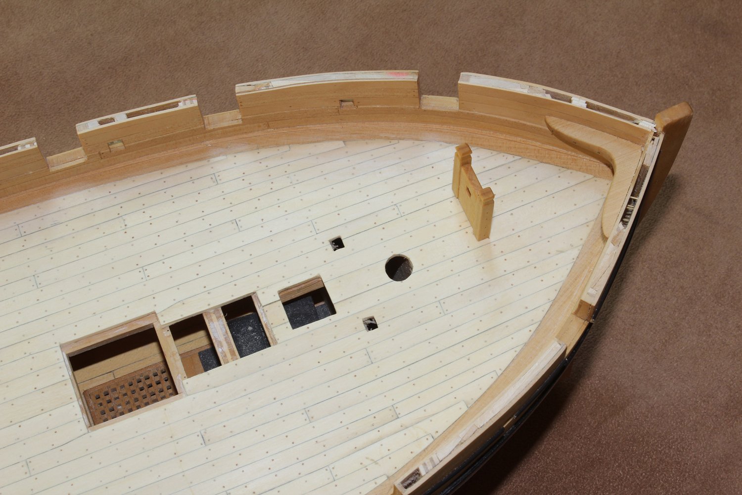
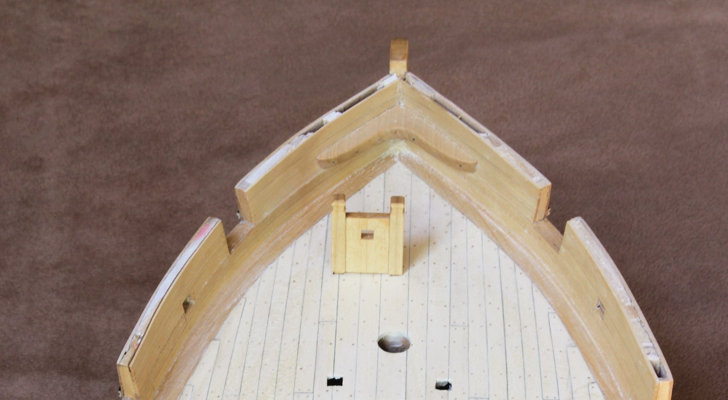
At this point I ran into a problem that I have not completely resolved. When you look at the bow section of the plan, you can see that the bowsprit is lashed to a stem head. There is a little decorative carving on it but most importantly, it appears to be rotated to starboard and the lower end of the stem head protrudes into the stem. Also, the stem rises above the rail. These are the reasons I initially decided that the bowsprit exits the ship on the port side of the stem. When I lined everything up, nothing made sense. The stem would need to be cut back severely on the port side to accommodate the bowsprit and the leading edge of the stem would need to flare because of the rotated stem head. The plan shows that there is no flare. The three photos help illustrate the problem.
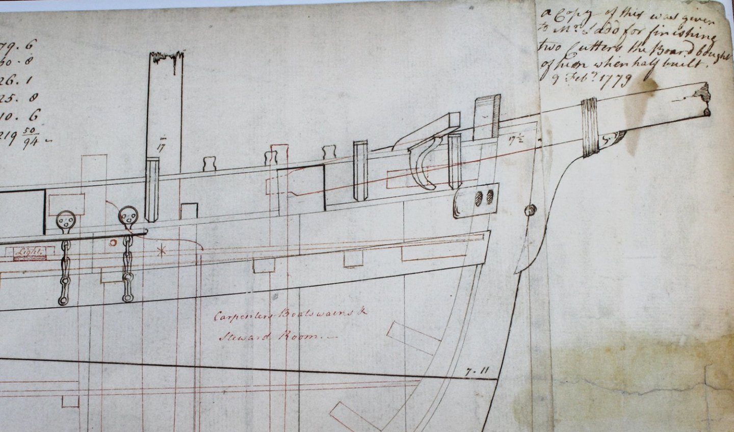
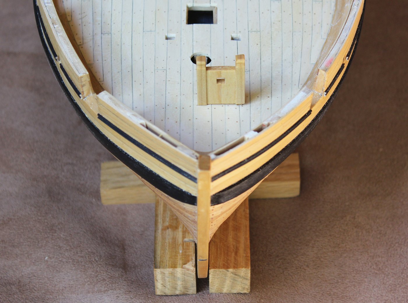


I did a search of all sloops plans in the RMG built between 1750 and 1820. There was not a single one with the configuration shown on the plans. The closest I found was Weazle 1799, built twenty years after Swallow but also built at Dover. On this ship, the top of the stem is shorter and the stem head does not show any rotation. My guts tell me to place it in the midline but I am willing to hear anyone's opinion on this.
-
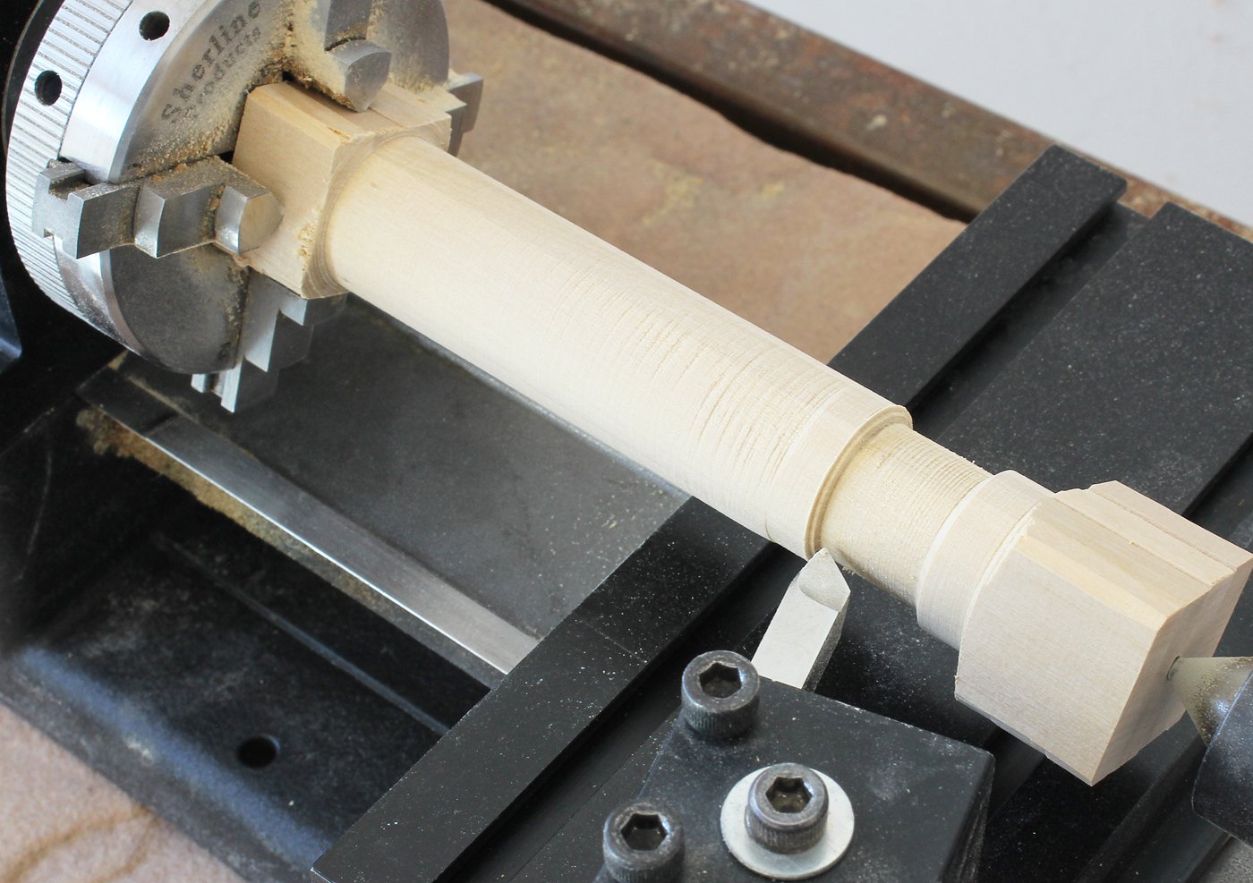
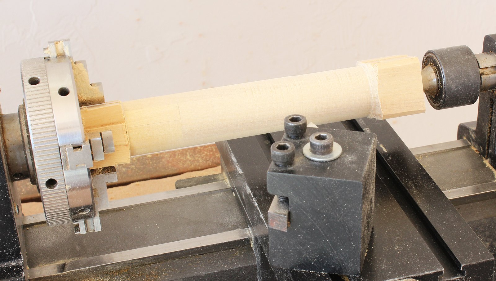
The barrel is made up from four smaller pieces of wood because at the scale at which I am building (1:16), a piece of wood 7/8 inch sq. would have been required. I started by chucking it up in the lathe and turning it down to the maximum diameter of 13 inches. Once that was done, I drew lines to note the changes in diameter. In the first picture you can see extra length at both ends of the blank. In the second one, the extra length is only at the chuck, not the live center. I discarded that part because I discovered that I could not mill the piece without support on both ends.
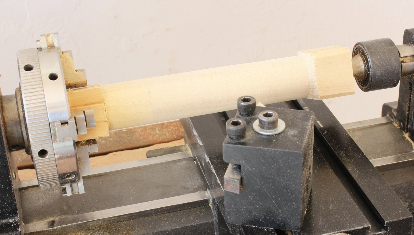
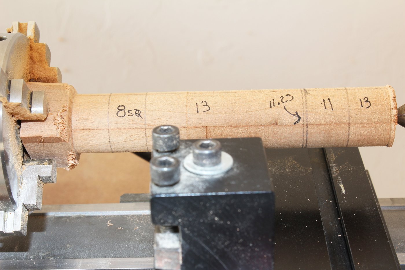
I started at the bottom of the spindle. You can see the 11.25 and 13 inch sections have been completed and I am working on the 11 inch section. The 11.25 inch section will be a gasket, preventing the whelps from rubbing against the capstan step. After all, we want this capstan to be able to turn when completed.
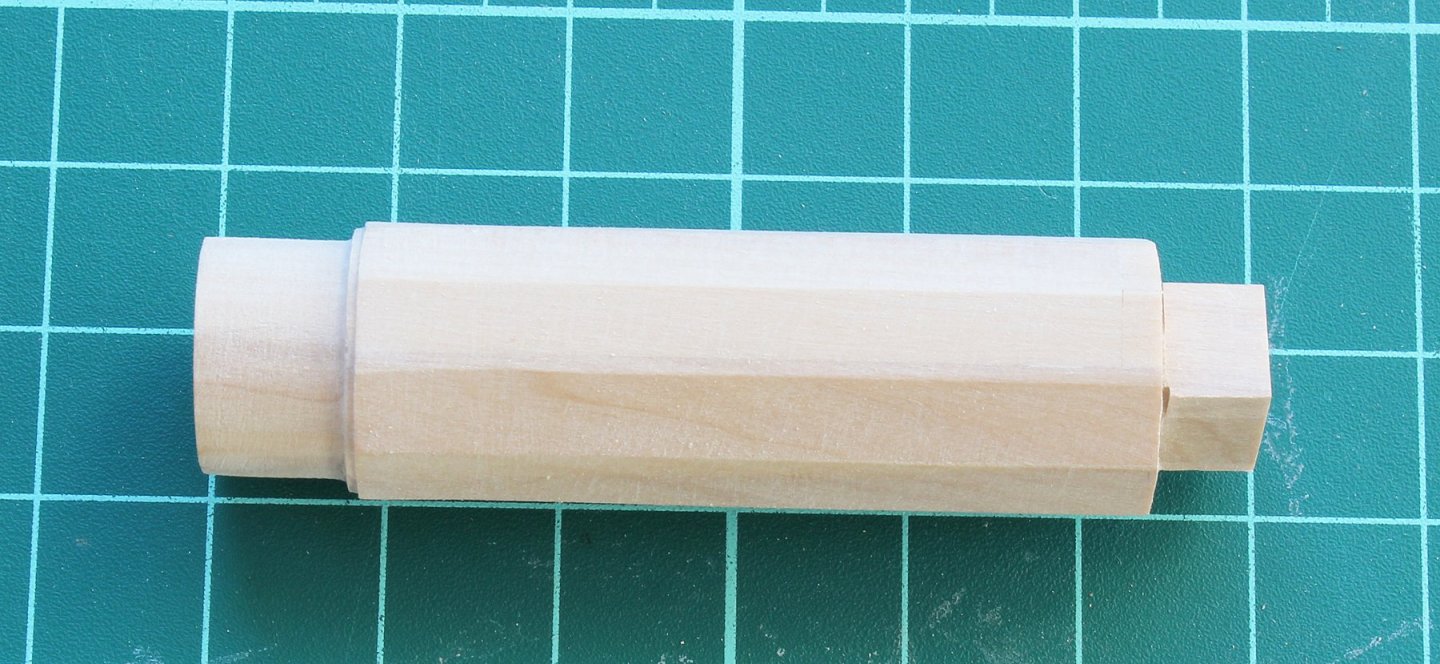
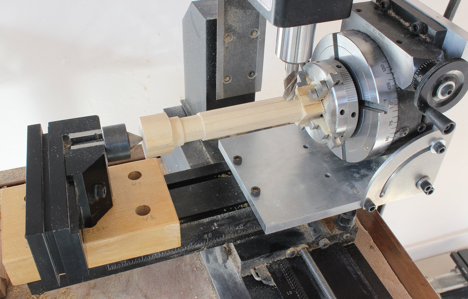
The spindle was removed from the lathe and mounted on the mill. I kept the spindle in the four-jaw chuck and screwed the chuck into the rotary table. I had to Rube-Goldberg the other end for support and to keep it level. In this case, the live center is held in the mill vise. This was raised above the bed as required. It was easy enough to hold the vise in one hand while moving the bed with the other. Once one face was completed, the table was turned 18 degrees and the next face was milled until completed. Next, the square head was milled and the piece was removed. The supporting wood was cut off both ends and the lower thirteen inch section was removed with a razor saw. This piece will become the retaining pin to secure the barrel to the step.

-
-
-
The step has been temporarily installed onto the deck. You can see the half-lapped joint in the red circle.
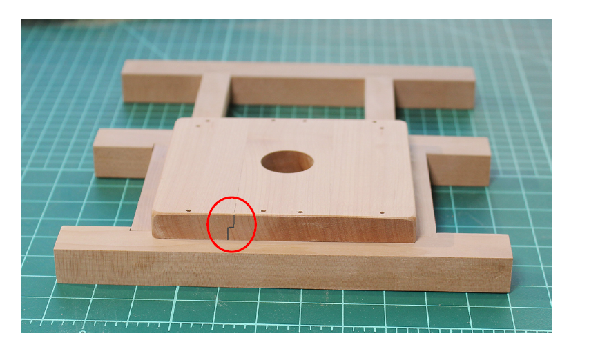
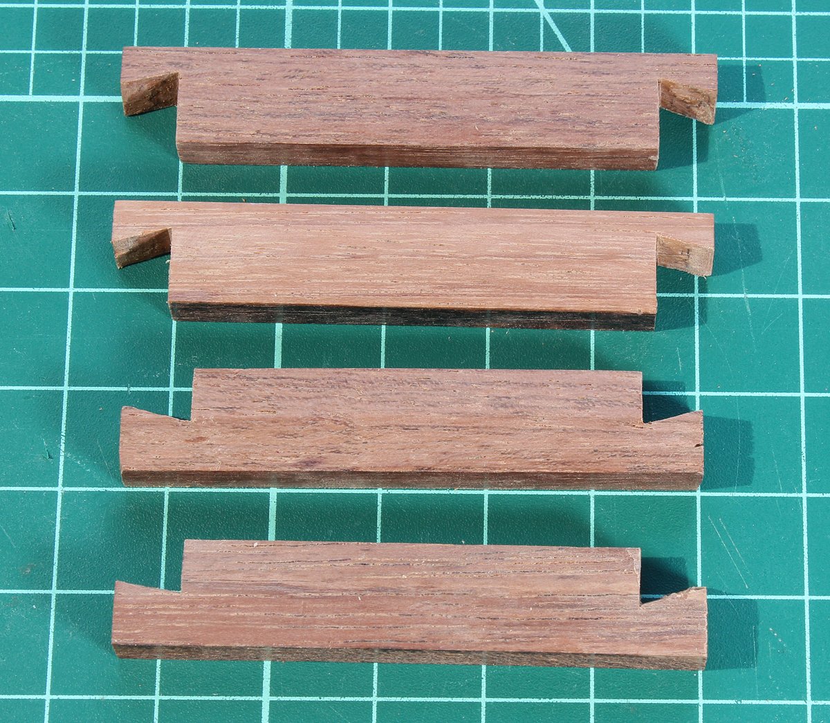
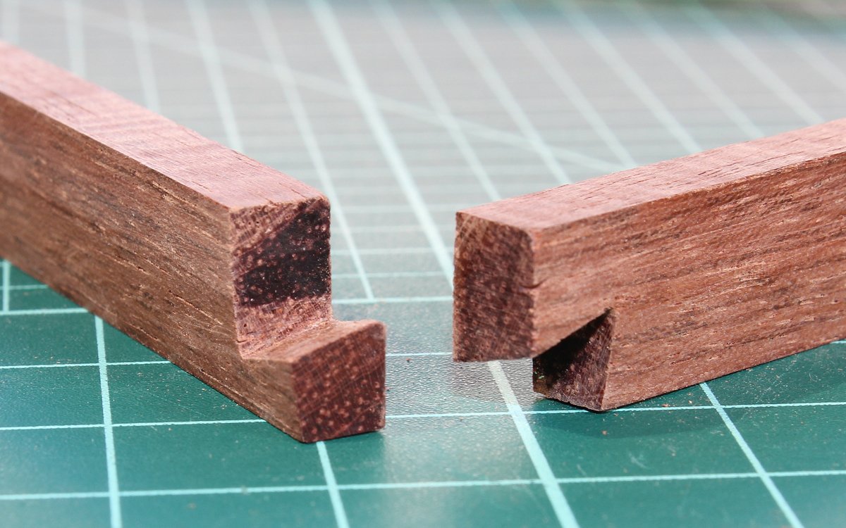
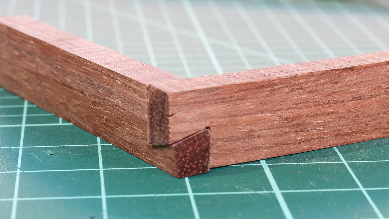
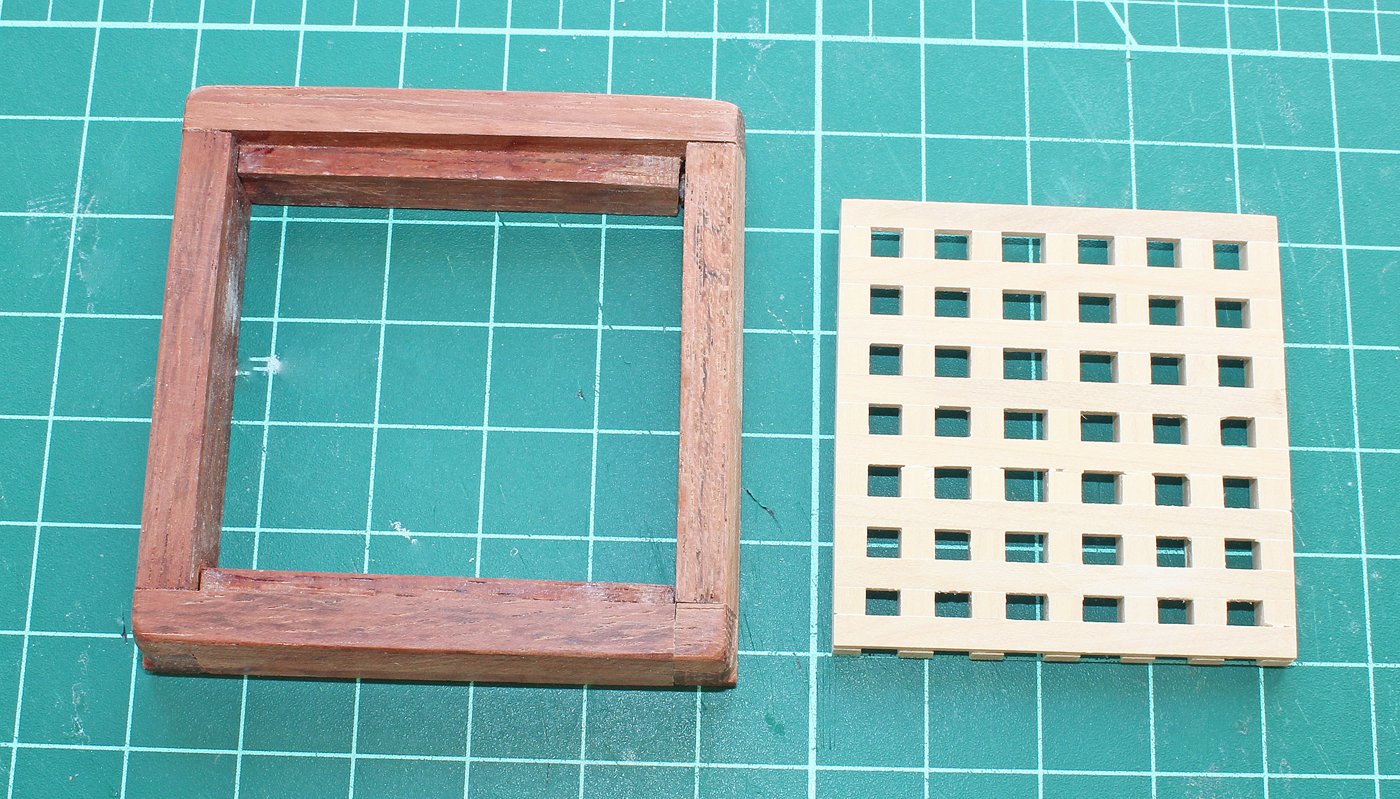
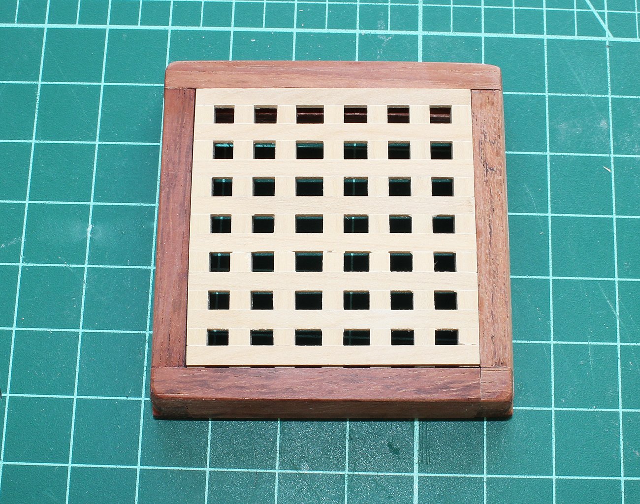
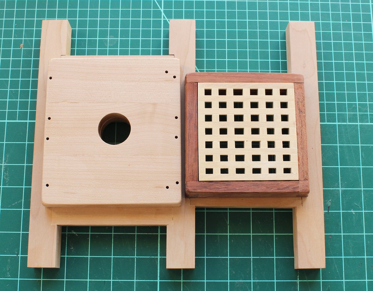
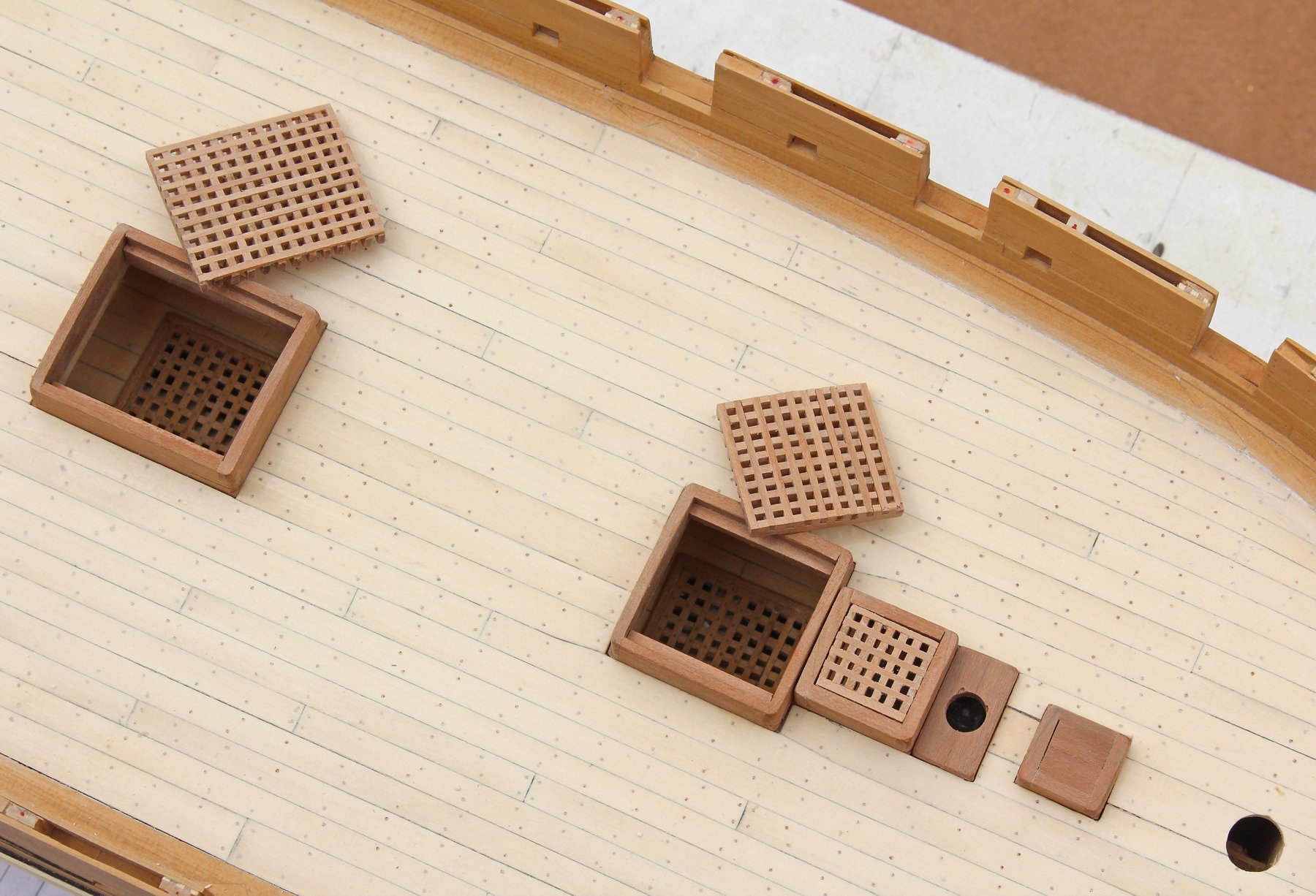
The hatch is next. In contrast to the intermediate version, the head ledges and coamings are joined with a locking half-lap joint. This prevents the corners from pulling away from each other. I could not find any easy way of making the joints. The best advise that I can give is to make everything oversized and, once you are happy with the joints, sand the pieces down to their final height and length.
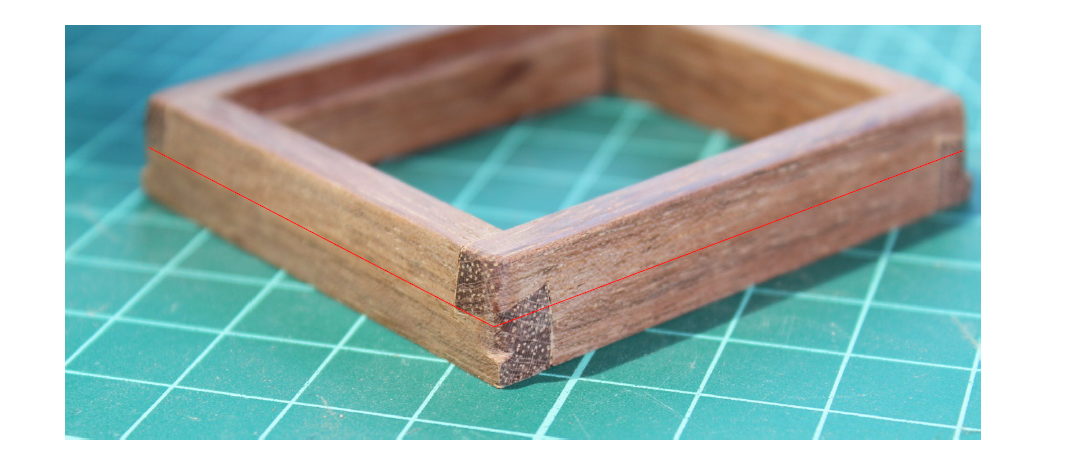
After the hatch has been assembled, glue in the rabbet (hopefully doing a better job than I did). The sides of the hatch are vertical for the lower four inches. Above that, as shown by the red line, the outside surface tapers inward by one-half inch. I used a sanding block to obtain the final shape. Chamfer the top edges and the corners down to the level of the deck. Grating was discussed in the intermediate version.
-
Despite what is expected by a large number of people, information is not free. Academic journals and most professional journals require a paid subscription to access published information. In fact, I would not trust the content of any free access journal. Those journals are called throwaways for a reason.
- Rik Thistle, mtaylor, dcicero and 7 others
-
10
-
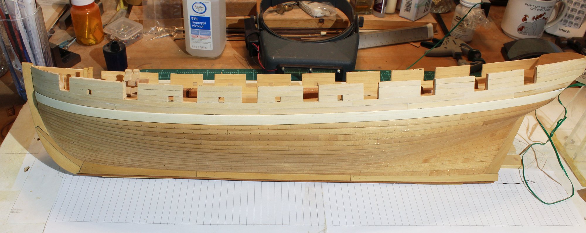
I was unhappy with the appearance of the upper hull planking. As was pointed out to me by Druxey, the decorative strip would have been applied on top of the planking, not between the planks. They were also too wide. The next two pictures show the planking before the last row of hull planking was installed.
I removed all of the upper planking and the decorative molding. Instead of four rows of planking, there are five. Much better.

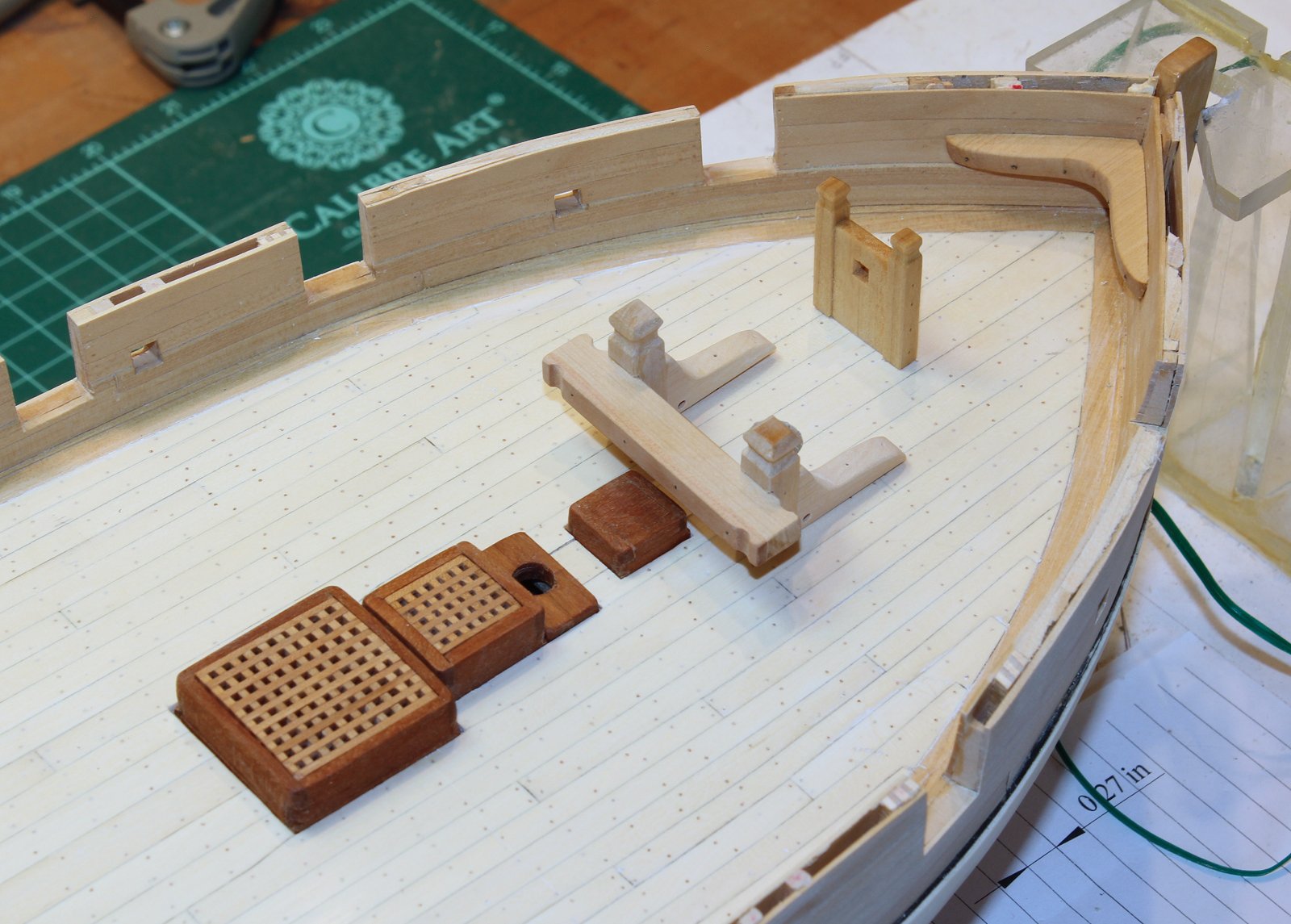
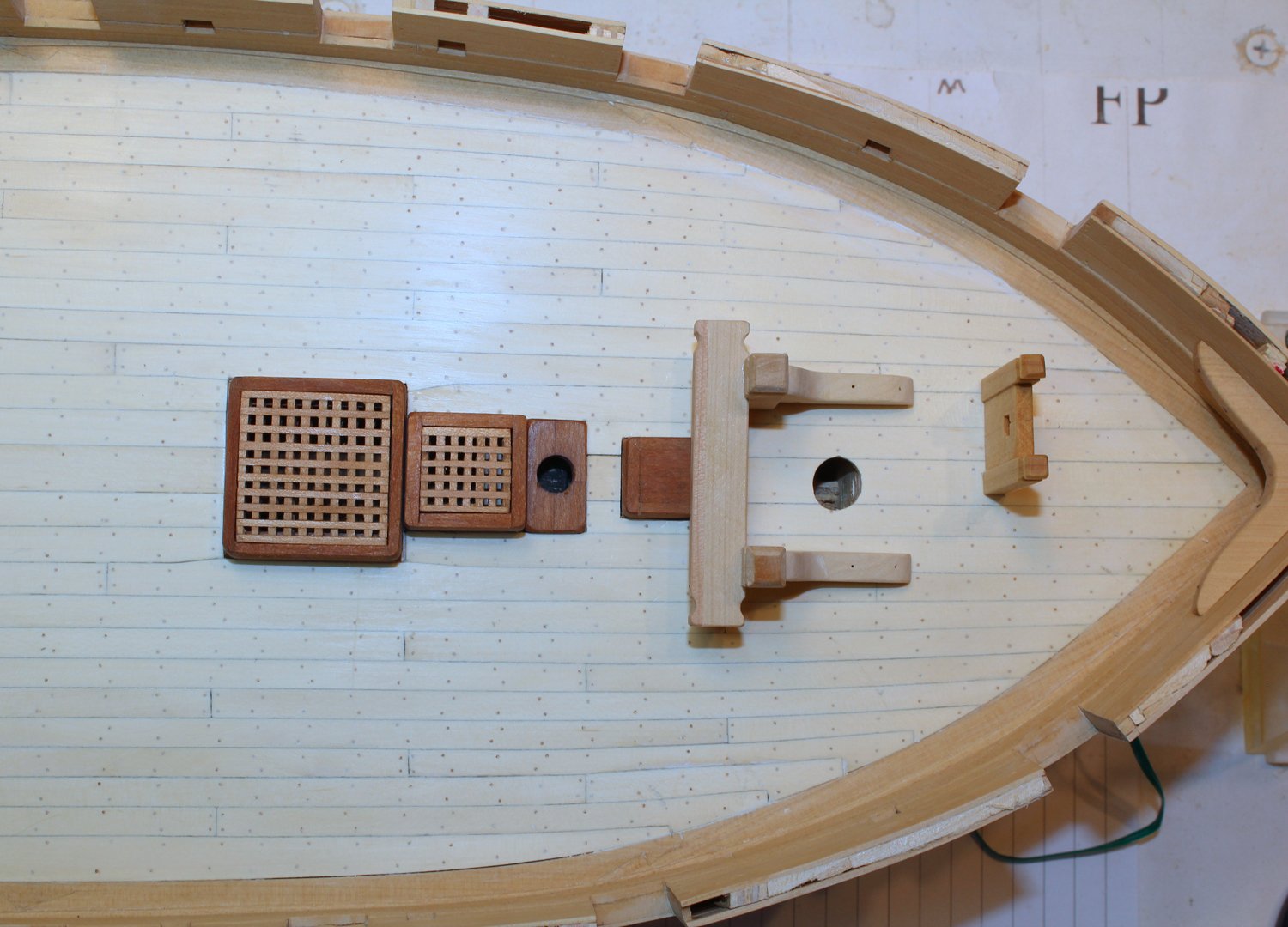
The bowsprit step and riding bits were made next. The bowsprit is offset on this ship, which is why the step is to the port-side of midline. The size and location of the riding bitt was taken from the plan. The primary wood is castello and the aft strip is pear for contrast. Nothing will be glued down until all of the exterior work is completed.


-
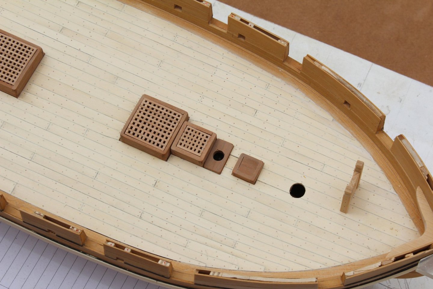
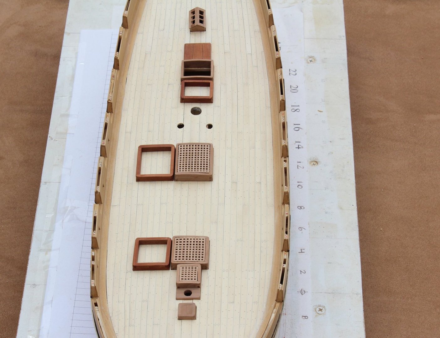
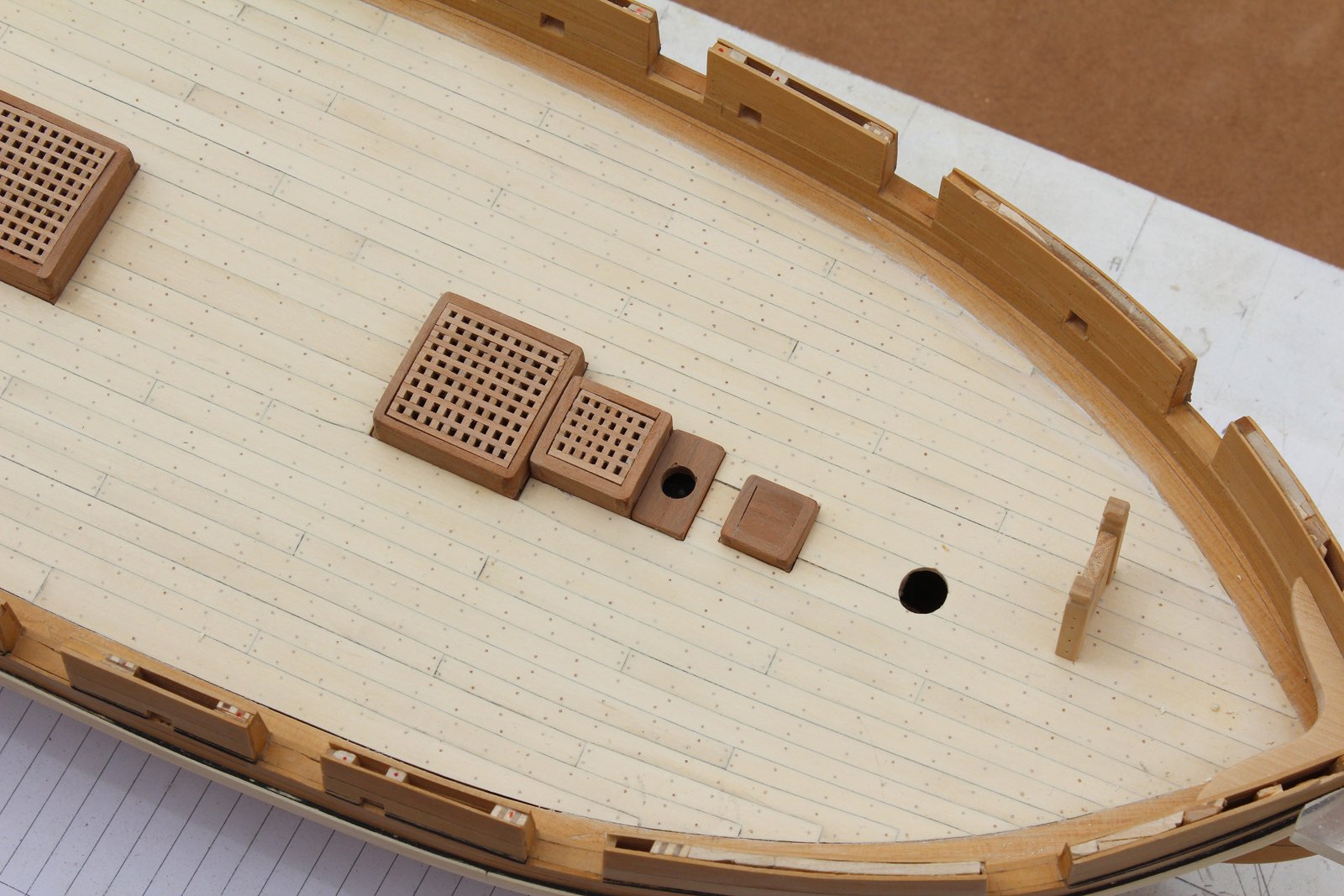
As mentioned earlier, I built the hatch coamings too short. These have all been remade and the gratings installed. I will not glue the gratin down over the hatches to allow one to see the lower deck. The steam vent (in front of the fore hatch) is glued down. In the middle photo you can appreciate the height difference.

At this point I noticed a problem. Even though the holly I use is several years old, a crack started to develop between the main hatch and the ladderway. Part of the problem was insufficient support for the deck because this was built plank on bulkhead without a subdeck. I gave the deck more support by installing a "beam" just aft of the main mast. This was accomplished by inserting the wood through the ladderway and holding is secure until dry. I could not get a clamp with a deep enough throat to fit through the opening. That part of the deck was resanded and the result is seen in the second picture. Big improvement.


Swallow 1779 by tlevine - FINISHED - 1:48 scale
in - Build logs for subjects built 1751 - 1800
Posted
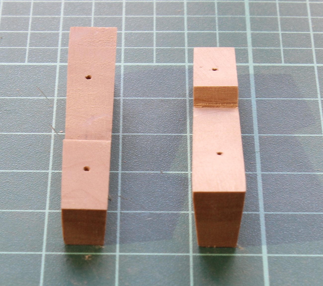
The bollard timber heads have been remade. As I was making version one, I knew there was something wrong but could not figure it out. As druxey stated, the inner and outer (athwartship) faces of the bollard head runs parallel to the keel. I have made an opening in the sheer rail for the timber rather than gluing it on top, as I did in version one. A thin piece of boxwood was bent around a dowel and used to fill simulate the bollard timbers alongside and below the bowsprit.
Treenails in the grating were simulated with a punch. A pencil was twisted in the depression to represent the treenail. Bolts made of blackened brass wire have been added to the bowsprit step, bitts and anchor lining. Mast wedges for the fore and main masts were made up from four smaller pieces of castelo, glued together. These were turned on the lathe. The opening was made using a mill with a rotary table since I did not have bits the correct diameter. The multiple wedges were simulated with an 11 blade. The skylight was glazed with sheet mica.
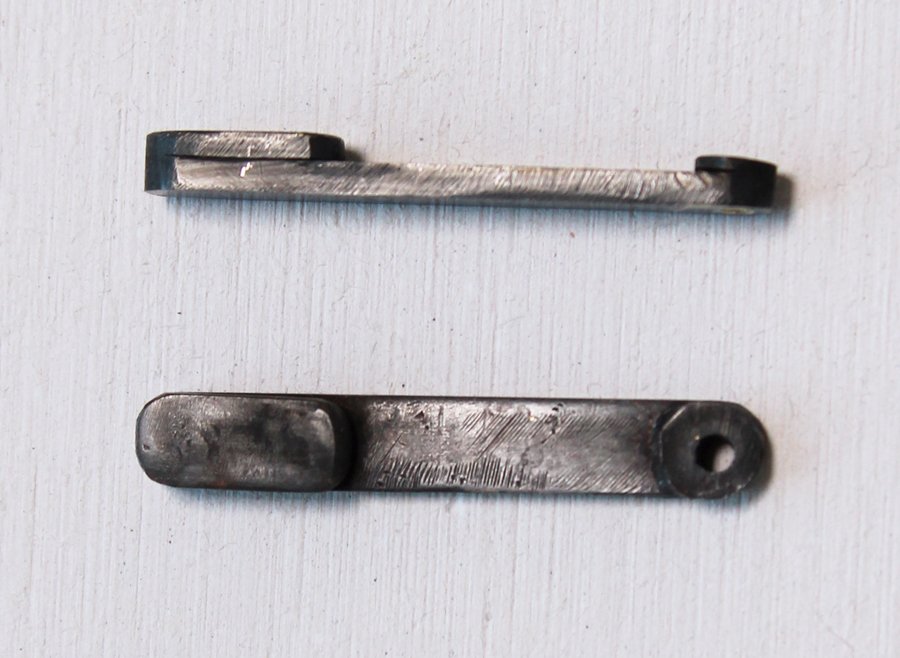
Most of the external details (other than the channels and deadeyes) have been finished. While it was still safe to hold the hull upside down, I installed the horse shoes, ribbons and gudgeons. The horse shoes and ribbons are left over from the photoetch sheet once sold by Admiralty Models. Recesses were carved in the stem, sternpost and keel for them. The pintles and gudgeons were made from brass square stock, strips and wire. They were silver soldered and blackened. I used the method shown in TFFM. The sequence is shown in the diagram. First the brass rod and strips are cut to length. Next, slots are filed into the brass rod to accept the strips. They are soldered and the face of the rod is shaped. A hole is drilled near the front. For the pintles, wire is inserted into the hole and soldered in place. Once I was sure that the rudder could be unshipped, I removed it for safe storage. Question: would a ship of this size have a spectacle plate or would some other way to secure the rudder been used? There is no spectacle plate shown on the plan or the model.