


Hubac's Historian
-
Posts
2,987 -
Joined
-
Last visited
Content Type
Profiles
Forums
Gallery
Events
Posts posted by Hubac's Historian
-
-
Really nicely proportioned carriages, and excellent consistency of effort and standards.
- Siggi52, mtaylor, Keith Black and 1 other
-
 4
4
-
-
Well, since my return to work, the pace of work has slowed, but I have still managed to make good progress.
This evening, I completed the lower gun deck. Typical of my approach to this build - because I want it to remain fully intact over the next six or seven construction years (hopefully shorter😉) - I have over-engineered everything.
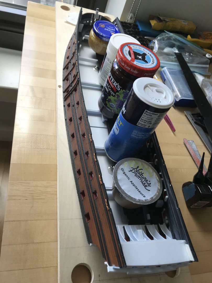
Once all of the dummy carriage blocks were in place, I decided to add backing blocks for a little extra connection/insurance, so that when I glue in the gun barrels, at the end of the project, I won’t loosen the dummy carriage blocks:
It’s total overkill considering the grip this particular cyano seems to have, but it makes me feel better.
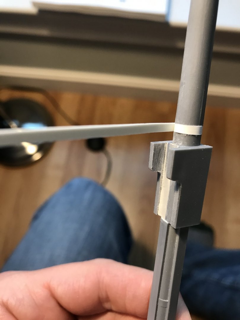
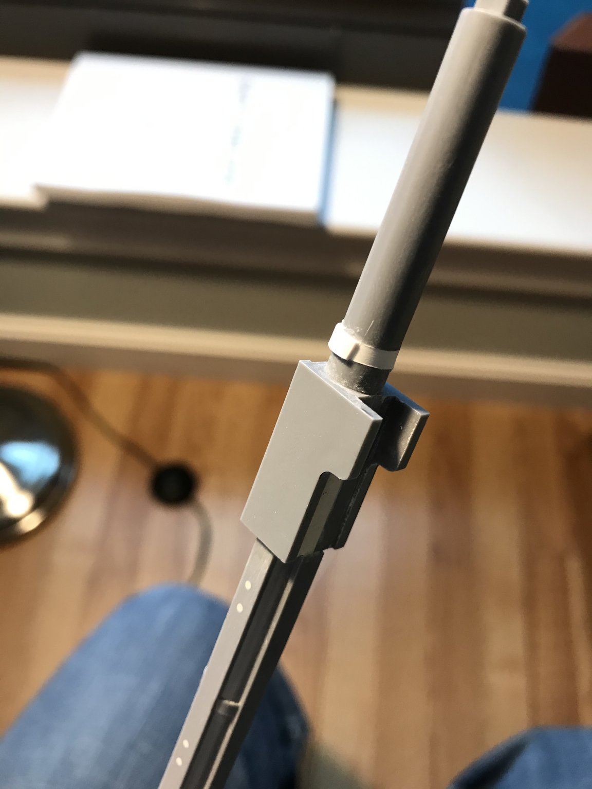
Likewise the fore and mizzen mast steps, which raise each mast 1/2” respectively, are over-engineered to insure that if the mechanical cyano bond fails, then the welded plastic collar will keep the mast footing in place.
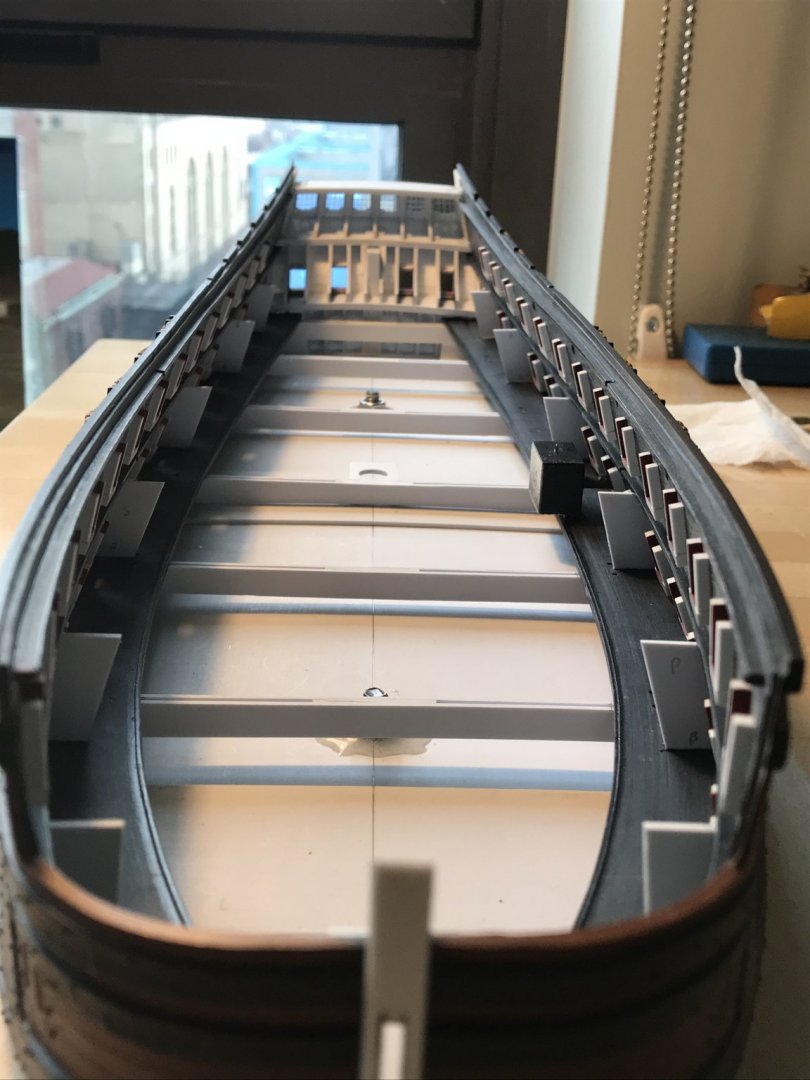
Once all of that was settled, I could fit and secure the middle deck “beams”: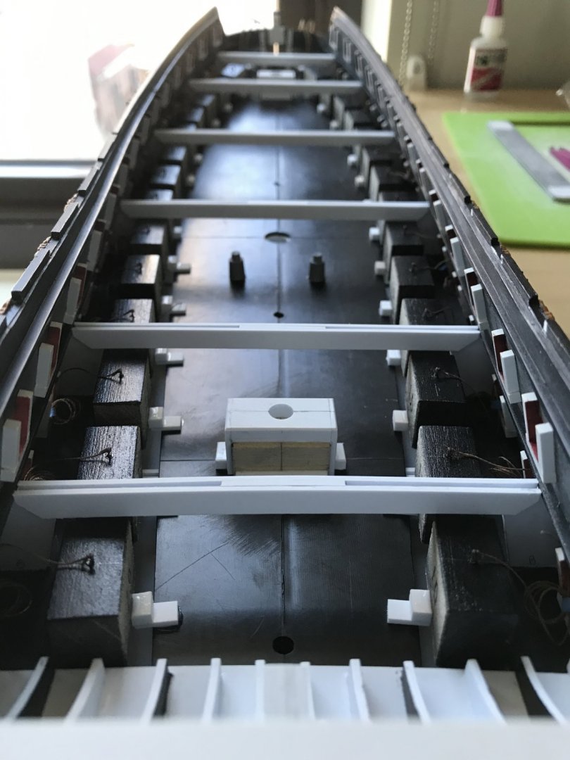
I faired their top surfaces, this morning, which enables me to begin the whole process all over again, with the middle deck. Interestingly, though, I discovered just how much the hull flattened out, when I cut away the bottom, below the waterline.
Roughly, along the waist, there’s a good 8”, or so, where the scribe is tight:
Splitting the difference, fore and aft though, it’s a different story:
These gaps are too much to scribe without foreshortening the waist depth (of these dummy carriage platforms) so much, that I have to create all kinds of additional carriage support.
I think my better bet is to make these carriage platforms from scratch, out of 1/16” white styrene. This way, I can still use the kit center deck sections, while adding back some of the gap space to the carriage platforms. This will enable me to place the carriages so that they don’t necessarily require as much out-rigger/backstop support.
Thanks to my good friend and mentor, Dan Pariser, I now have anchor cable, which I seized this morning:
I’m waiting for the grey acrylic I applied to the inside of the hawse holes to really cure before threading the hawsers. Thank you so much, Dan! These cables look really great and they are just the right scale.
Here’s a broadside view with all of my tapetags pulled through the ports, so that it will be easier to retrieve the port-lid laniards:
In other works, I made up the stock kit mizzen mast, which I reinforced with a straightened piece of wire coat-hanger. I did also try to turn a wooden mizzen in the chuck of my drill, but the first attempt was not satisfactory. I’ll have to learn how better to do this because all masts and spars above this level will be made from wood.
I also got busy, as a small-work project, making the sprit-mast, foremast, and mizzen tops. Here are the sprit and mizzen tops, which are the same size; I have yet to attach the top banding:
As a frame of reference, I found that Lemineur’s masting and rigging plan of the St. Philippe in 1:96 is an excellent corollary to what I am trying to achieve, proportionally. Going forward, as I did with the new top diameters, this will be my guide for proportioning the topmasts and t’gallants.
Here’s a shot of the side work, in process:
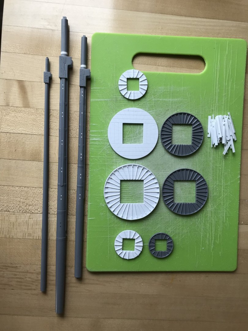
You can really get a sense of the increased scale of the new tops, here.
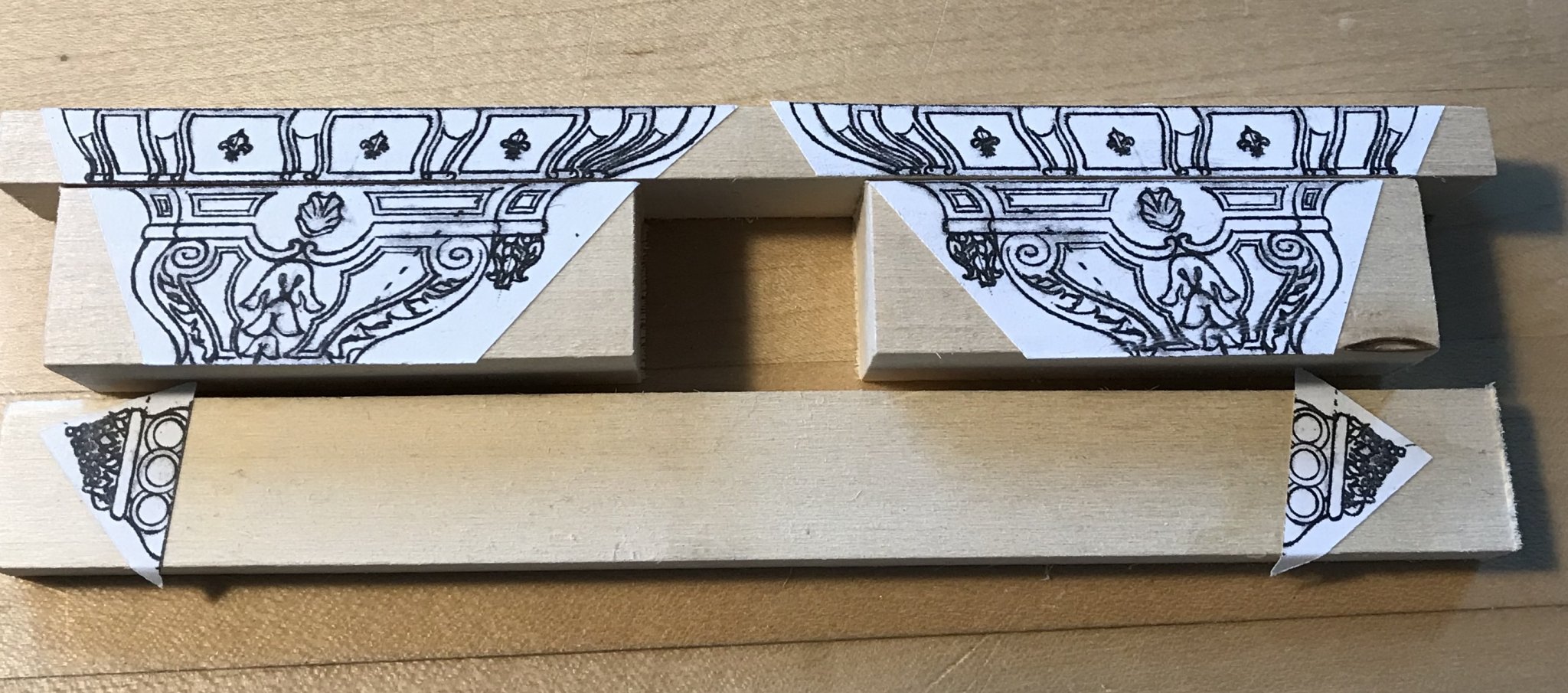
Lastly, I’ve begun preparing stock for the lower half of the quarter galleries:

These are ready for my next shop opportunity to profile them on the bandsaw. I still am not sure what the material is. At one of our club meetings, Dan was divesting himself of various odds and ends in his shop, when he gave me this stick of wood.
It has virtually no grain, a light yellow color (which I thought was oxidation, but remained so after milling), is lightweight, but fairly hard. I think/hope it will shape well and hold fine detail. We will see.
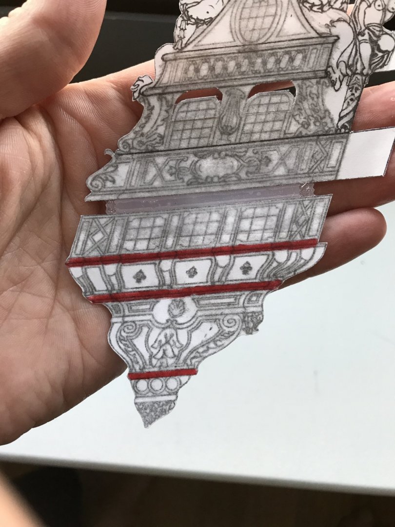
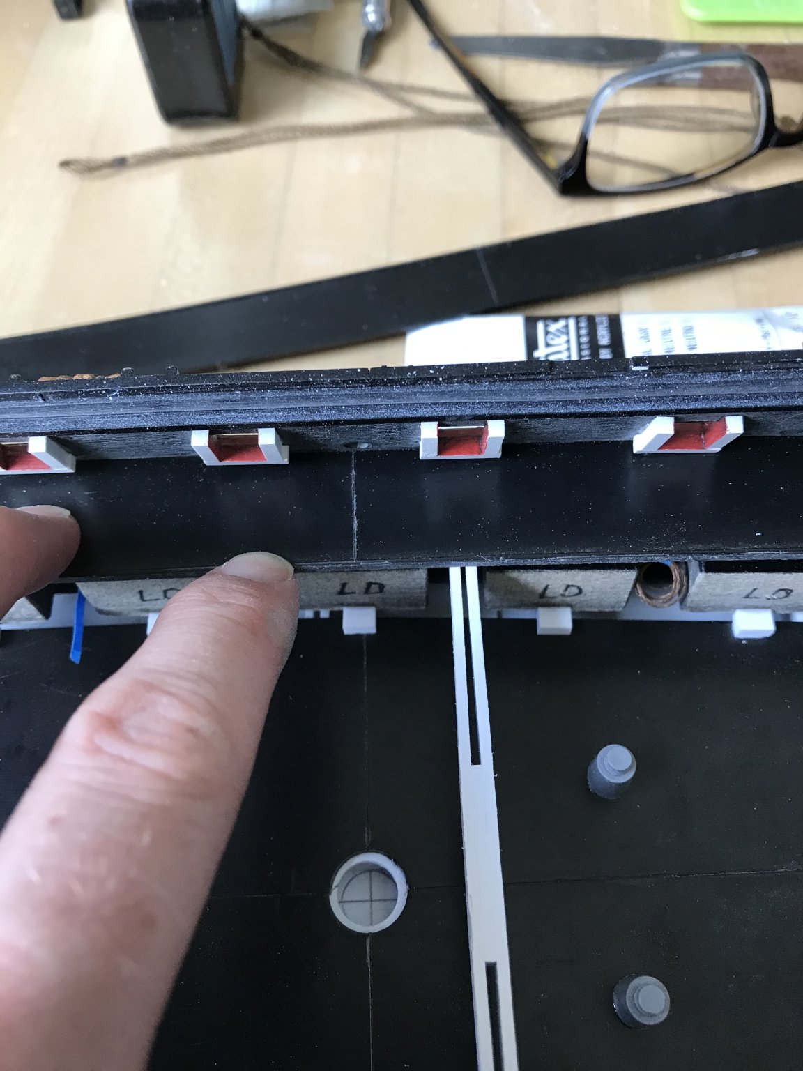
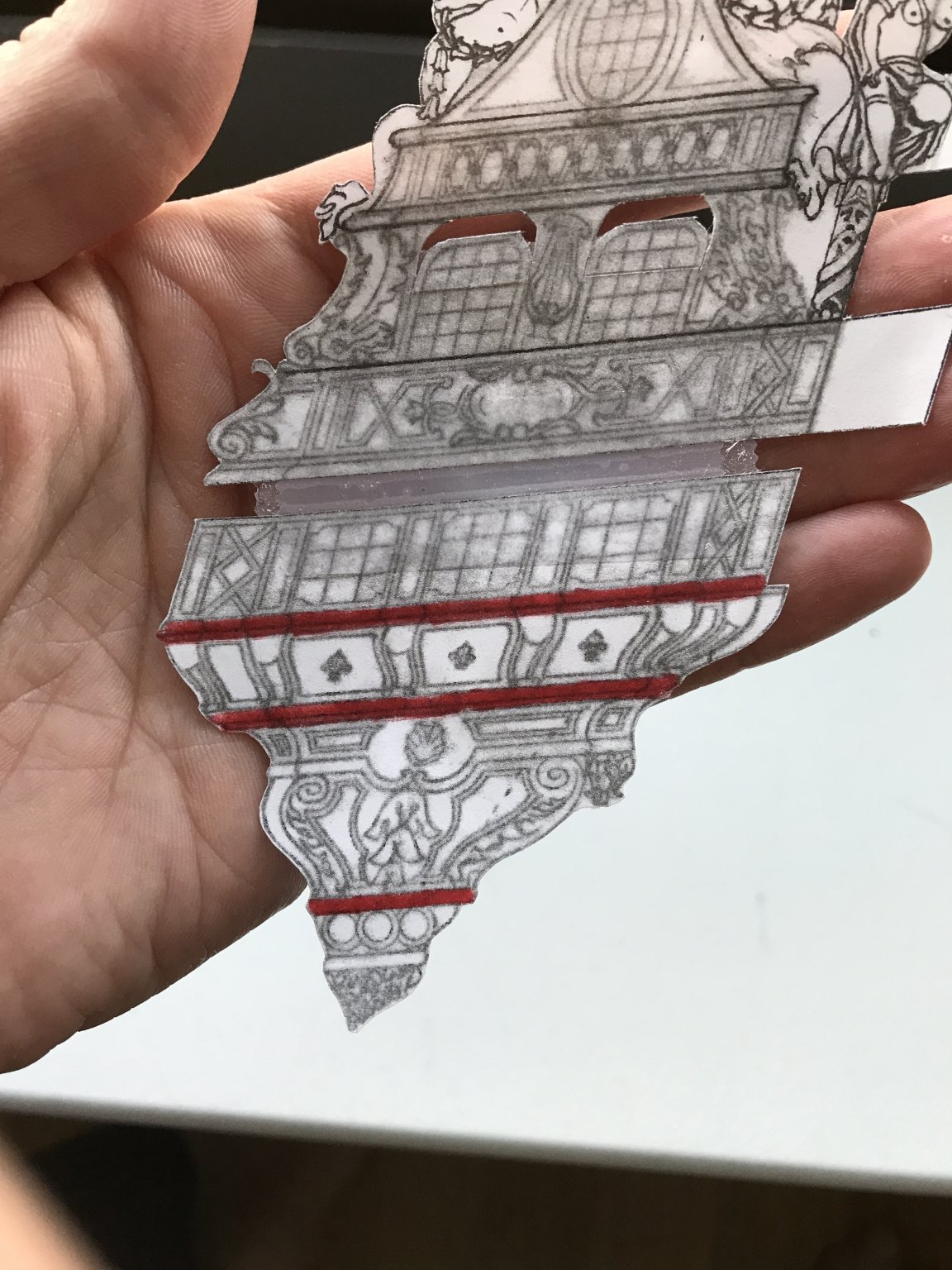
I will save any advanced description of my process for making the quarter galleries, until I am actually doing it. Suffice it to say for now, though, that these carved lifts will be sandwiched between moulding strakes of white styrene, that will define the shape and projection of the QGs at each level. The moulding strakes are highlighted, here, in red:
As ever - thank you for your interest and for looking in. Stay safe, sane and healthy, everyone!
- dafi, GrandpaPhil, EJ_L and 10 others
-
13
-
-
BRAVO, EJ! She really looks superb. This is a well-earned victory lap!
- Old Collingwood, BLACK VIKING, EJ_L and 1 other
-
4
-
Yes, it truly is mind-boggling. In 2003, when I was standing in the guts of the Provincien, at Batavia Werf, it was almost incomprehensible to me how tall the stern rose above the keel. The counter timber was gigantic!
You are really doing an incredible job, here, Mark. It’s fascinating to me, the questions that arise as one works through their process. And, as you say, it is astounding the complicated geometry that these shipwrights could render with their trained eyes and hands.
-
At the 3:11 mark, of the following video, the narrator is showing how Victory’s tiller operates, on the actual ship. Shortly after that point, you can see the tiller’s entry into the ship, and the same curved beam that you have fashioned, just beneath the entry point:
- mtaylor, garyshipwright, AON and 2 others
-
5
-
A very clever assembly jig, and beautiful results!
- Siggi52, Dowmer, FriedClams and 4 others
-
7
-
I love how the lighting turned out, EJ. What a magnificent job you have done by making all of the carvings yourself!
-
-
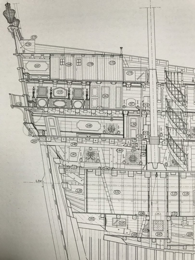
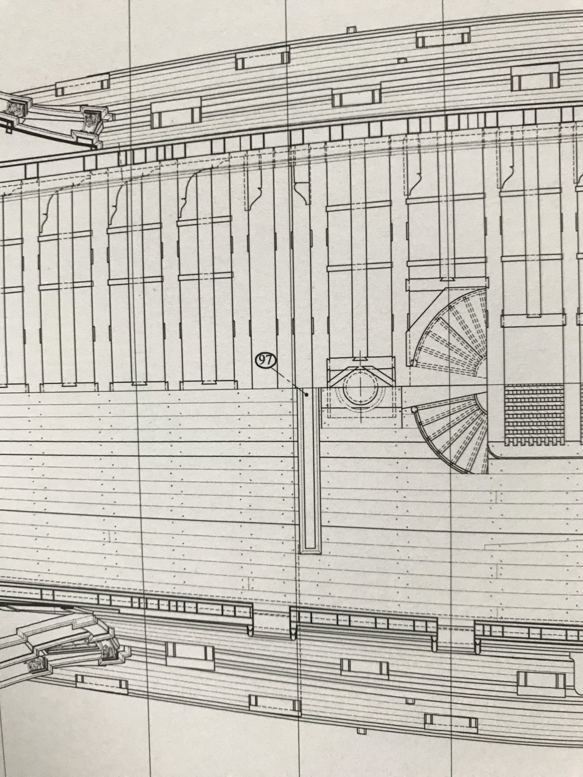
Chapman, this drawing from the Album, to my mind, definitively affirms the presence of the slot.
And, yet, there are a few curious things about the drawing. First - although the rowle is shown on the deck plan view, it does not appear to be represented in the cut-away view.
Second - the slot railings would seem to eliminate the possibility that the pilot stands on the main deck, and in any case the whip-staff isn’t drawn as projecting high enough above the railing for anyone to work it.
So, that would seem to place the pilot on the lower deck, and facing a bulkhead that walls-off the mizzen mast - far from the action and command.
It is puzzling given that these drawings are supposed to be a literal representation of how a French ship was constructed in the 1680s.
Mark, you are right about the Lemineur plans. The St. Philippe monograph is a stunning piece of work, but there are numerous inconsistencies and puzzling details that often don’t appear to make practical sense.
I joined the Ships of Scale site to watch one modeler, Nigel Brooke, build the S.P., according to the monograph. It’s early yet, in his build, but he’s making a spectacular job of it. His build-log is particularly insightful, concerning the vagaries of interpreting the plans, so that he can correctly loft his frames. Nigel is exceedingly sharp, but he has had to do an incredible amount of mental gymnastics to get to where he is now with the build.
The model is absolutely worth the look:
-
-
Jan, I think you have keyed-in on something fundamental to this discussion: the schaarstokken, or as I think they are called in English - the King Planks(?).
These longitudinal stiffeners - because they are mortised into the deck beams - would compensate for the presence of the slot.
Nonetheless, Leminuer’s drawing shows the slot crossing both pairs of King Planks, but that does not, in itself, invalidate your argument.
Certainly, for all practical purposes, the slot must cross the first pair, closest to the centerline of the deck. However, given the down and over mechanics of steering hard to either port or starboard - is it really necessary for the slot to be so wide that it crosses the second pair of King Planks?
Considering, also, that the guns would recoil into a slot this wide, and I think there is an argument to be made for a drawing error, in this instance.
-
-
My issue with this is that the tiller man, the pilot, on the three-decker is standing on the middle deck, in this scenario, and that much further from the chain of command.
There’s a lot of superstructure above him on Soleil Royal, with no view of anything but the mizzen mast and the guns to either side of him.
And I’m sorry to disagree, but the pilot will have more leverage to push down through the yoke, the fulcrum, and to either side if he’s standing at the end of the whip-staff, as opposed to closer at the base. The length of the whip-staff counts too.
In all fairness, this discussion of mechanical advantage heads straight towards why ship steering transitioned from the whip-staff to the wheel; as ship sheer reduced into the 18th C., the wheel system provided greater mechanical advantage with every rope turn around the drum.
-
Hey Dan,
Your points are well received, here. The Goodwin drawings, as well as the contemporary French drawing, is of a two deck ship, but our discussion pertains to three deckers: I wonder whether the extra deck of separation (the middle deck) wouldn’t provide the extra leverage that would make steering such a large ship much easier, particularly in a heavy seaway.
Admittedly, it is less than ideal to interrupt the deck planking, at the main deck level. I wonder, though, whether the external wales, the internal riders, and all of the internal supporting knees mitigate this loss in rigidity.
-
Hello Papsa,
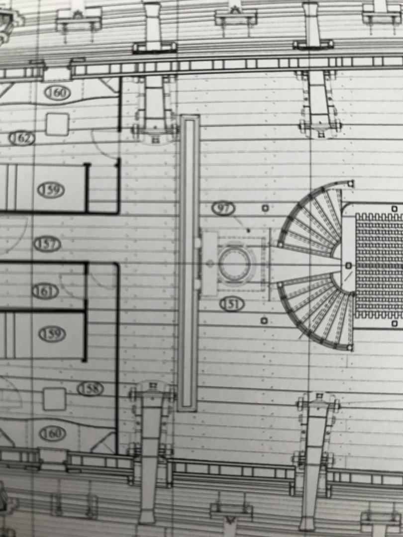
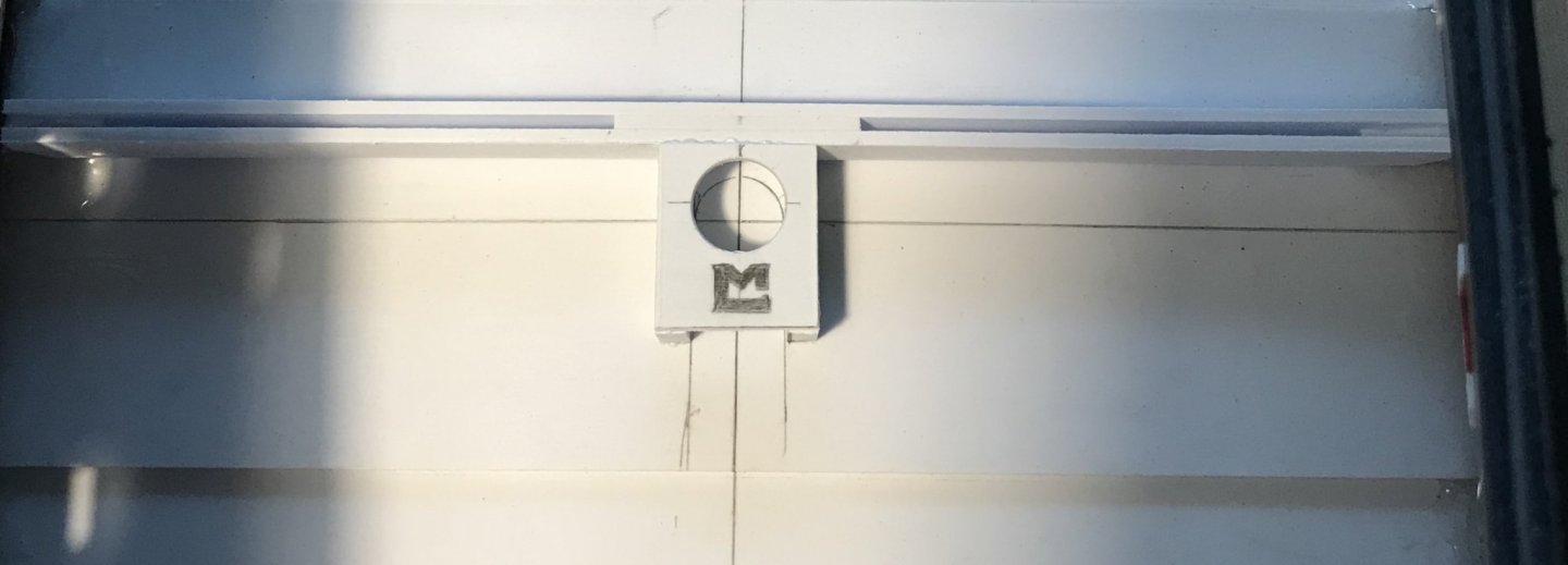
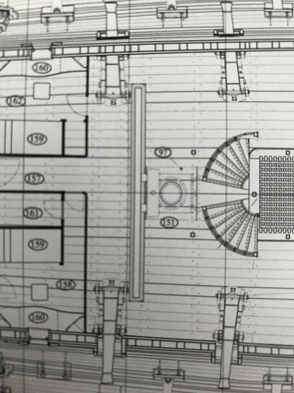
With regard to the tiller/whip-staff arrangement, here is what Mr. Lemineur drew for the St. Philippe:
Tiller entry is on the lower gun deck. The whip-staff passes through the yoke, in the middle deck, and then through a slot on the main deck - all just aft of the mizzen mast.

The whip-staff slot is numbered 97, in the main deck drawing above.
There does not appear to be any visual accommodation for the tiller man, through the quarter deck. It seems that commands to the tiller man would be shouted down, through the aft companionway, just forward of the mizzen mast.
I know we are accustomed to seeing on reconstructions, like Batavia, a small “grill” at the quarter deck level that the tiller man could see and hear through. I, myself, have stood on the small bench platform on Batavia and peered put from this grill. For all intents and purposes, though, it is not as though the view afforded the tiller man, in this arrangement, would enable him to guide the ship through his own eyes. On a large ship like the S.P., or the S.R., as long as the highly specific commands could be heard, that would be sufficient.
I also have to imagine that the view from the poop-royal deck would provide a sufficient vantage point to see all around the ship, while the bow, midship, and quarter watches would be communicating, aft, anything unusual in their view.
Thank you, Druxey and EJ! It is nice to have some phase of this project moving along at a swift pace.
-
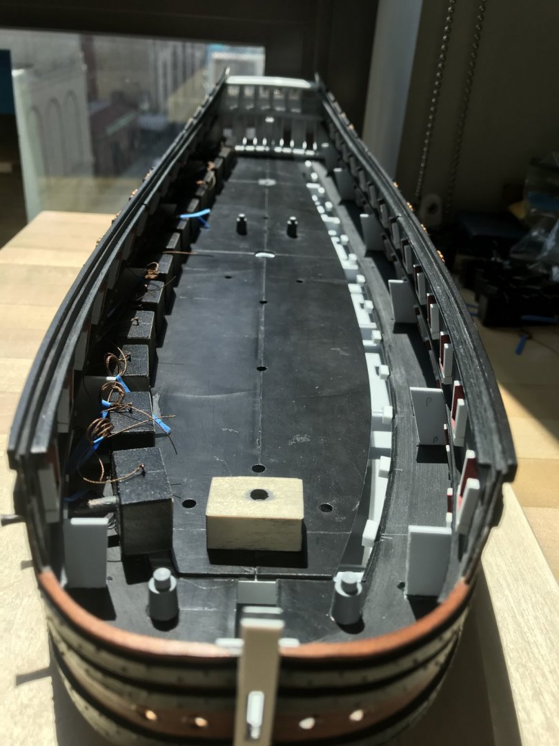
The wiring is actually the port lid lanyards, which I’ve secured to the top of each dummy block with a clove-hitch. I’ve coiled them up with blue tape for tidy keeping, until I pull them through the ports, at the very end of the build.
As a matter of fact, I cook with the pink salt, but I keep this other stuff for mouth irritations and stove fires.
-
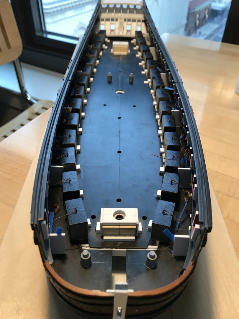
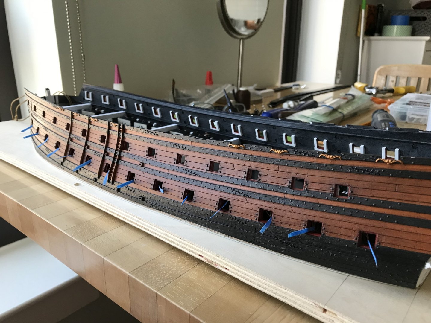
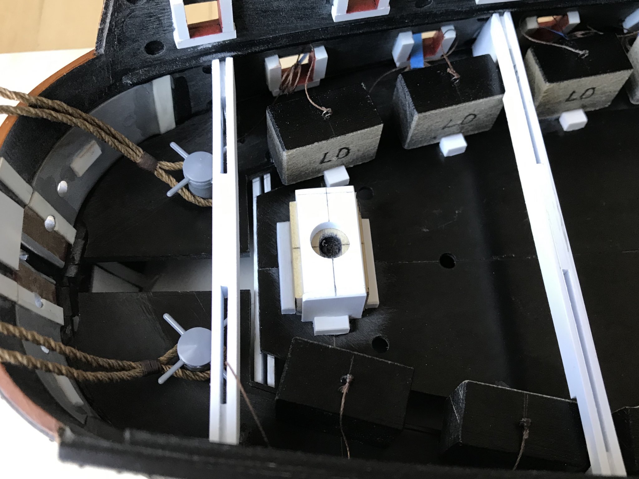
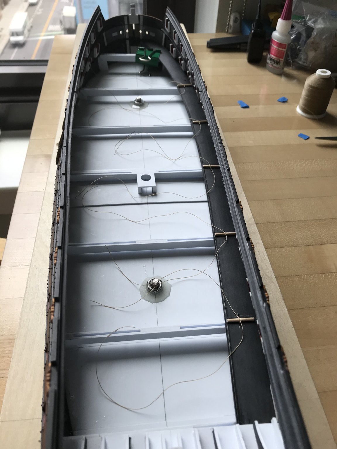
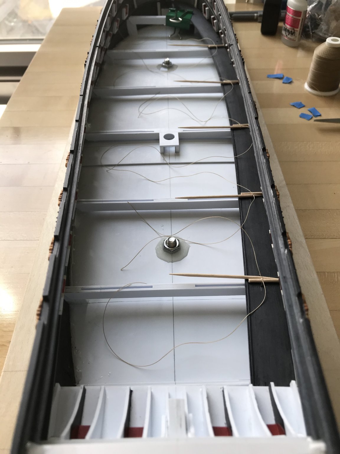
Good couple of days. I have all the lower decking installed, the cable mounts installed, and the starboard dummy carriages glued-in; the barrels are only temporarily placed to ensure they are centered on the port openings:

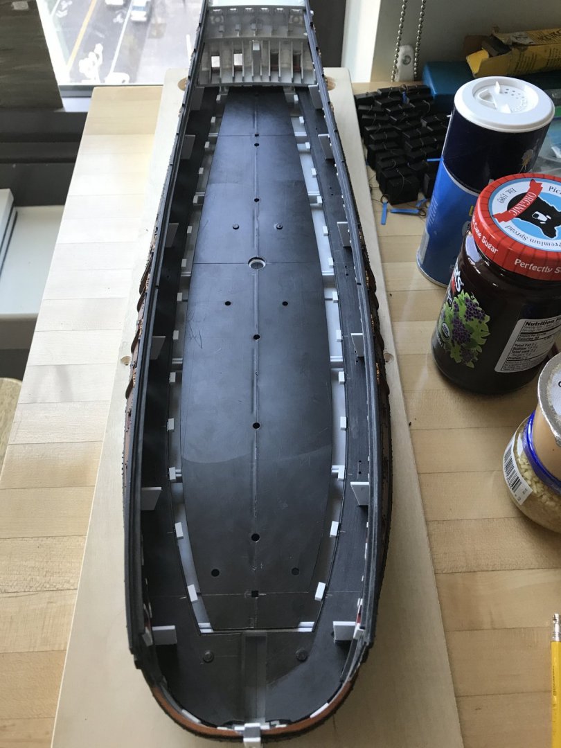
You can clearly see, here, the impact of broadening the hull.
The block, at center, is the foremast step (in progress), which will raise the height of the foremast proportionally with the main mast.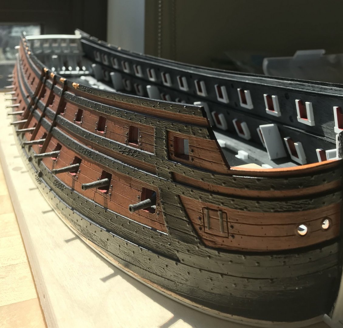
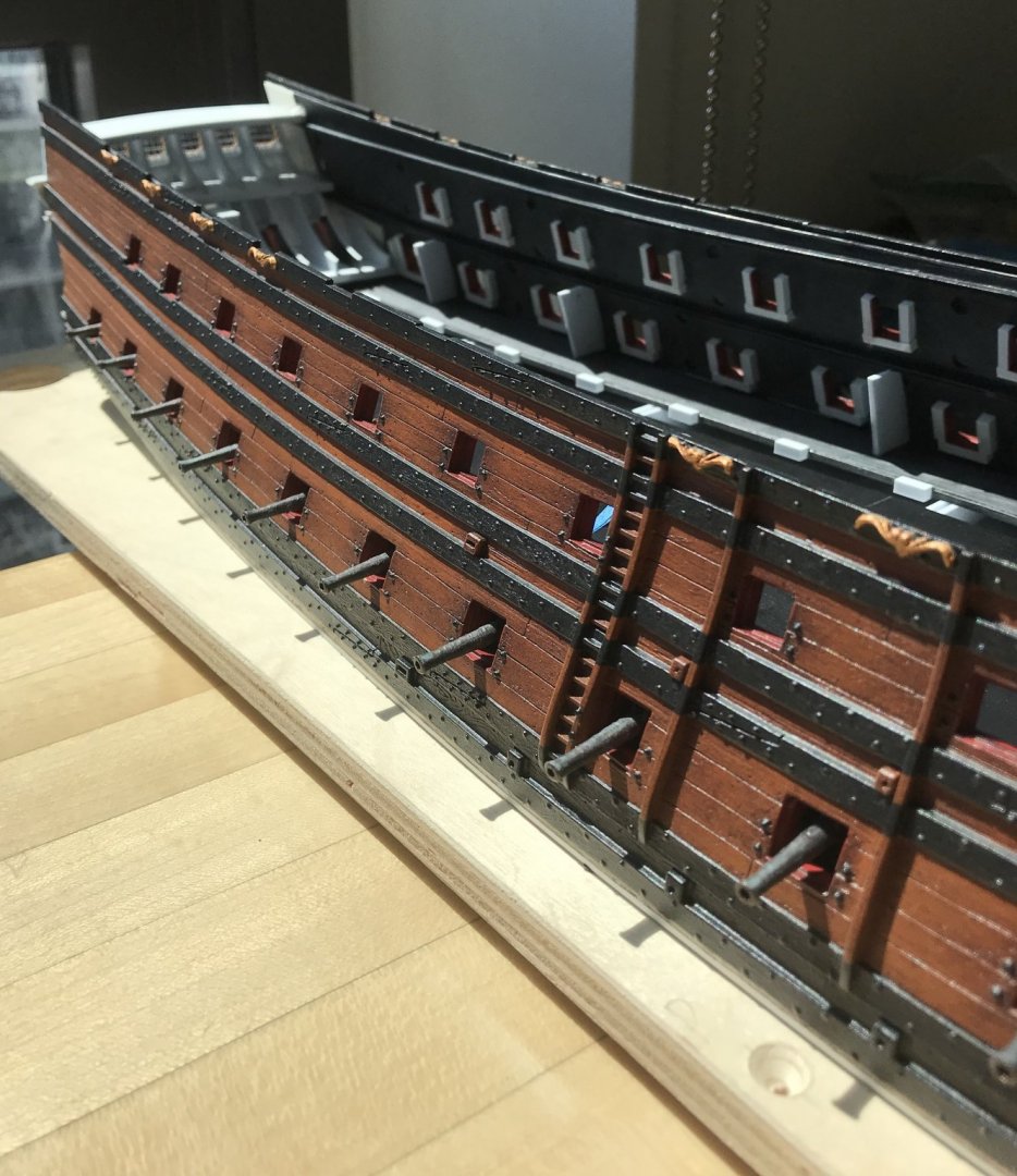
Barrel projection is maybe a bit more than ideal, but it’s not markedly different than Frolich’s L’Ambiteaux:


In any case, it’s a warship, and the artillery is supposed to feature prominently. I have a good cross-vent going, but I have to take a cyano break for a little while.Thank you for the likes, the interest, and for looking in.
- druxey, mtaylor, marktiedens and 6 others
-
9
-
Thank you, MD and Victor. Well, as you know, I’m a huge fan of the Heller kit, and the main reason for that is that they were extremely attentive to re-creating Tanneron’s sculptural work.
This is why I will go to some lengths to adapt as many of the large sculptural figures as I can. With the exception of Africa, whose entire posture has to be altered, I should be able to re-use them all.
You made me think of another Heller prestige ship that was very finely moulded, and that was La Couronne, at 1:200.
I used to own this kit as part of a large stash of un-built plastic kits. When I moved into my then girlfriend’s studio, before we married, I divested myself of all but the Airfix Prince and Vasa, which I deemed to be the best among the lot.
I should have held onto La Couronne, though. This is another kit that would benefit tremendously from cutting away the lower hull, and building all of the deck furniture from scratch and to scale. The overhang of the stern counter is exaggerated, but it could be modified, somewhat. The upper bulwarks were gems, though. Aaaah, well - the things we sacrifice for love!
- mtaylor, druxey, BLACK VIKING and 4 others
-
7
-
It is refreshing, periodically, to shift between the intensive ornamental aspects of the build, and the more constructive bones of the project. I enjoy the ornamental work very much, but it is fatiguing.
So, I’ve been fitting-out the lower gun deck. The first order of business was to scribe and secure the side platforms that will support the dummy carriages.
Clamping these to my “beams” was tricky because clearance between beam and plinth base is very limited. I could get a binder clip on, near the hawse holes, but I needed to develop a system for the rest of the way.
Since none of this will be visible, I decided to drill holes on each side of each beam, through which I could thread ties that I could pull taught over a short length of toothpick (temporarily secured with double-stick tape), and then fix down tight with a drop of cyano:

This worked beautifully. I then found that I could increase clamping pressure by wedging the end of a second toothpick into the tie-loop:

Once the liquid plastic adhesive had cured, I knew that I had solid connection all along the length of the hull.
Next, I wanted to scribe and secure the vertical gussets to which the middle deck “beams” will be secured. I was careful to space them so that they did not interfere with the lower masts.Simple templates were cut from index cards, and with only slight adjustments one template could produce gussets for that location, on both sides:


This has become a pretty straight-forward framing exercise that I’ve gotten to be pretty efficient at. Here is the full run of gussets in place:
Finally, I wanted to get a sense for where my dummy carriages needed to be placed, in order to have the right amount of gun barrel poking out the side of the hull.
Here is where I discovered a few issues that I did not properly anticipate.
First of all, my early estimate of the gun platform decking thickness, combined with the height of the gunport sills above the decking, was off. So much so, in fact, that a barrel inserted into a dummy carriage was resting on the sill. I drilled the holes too low.
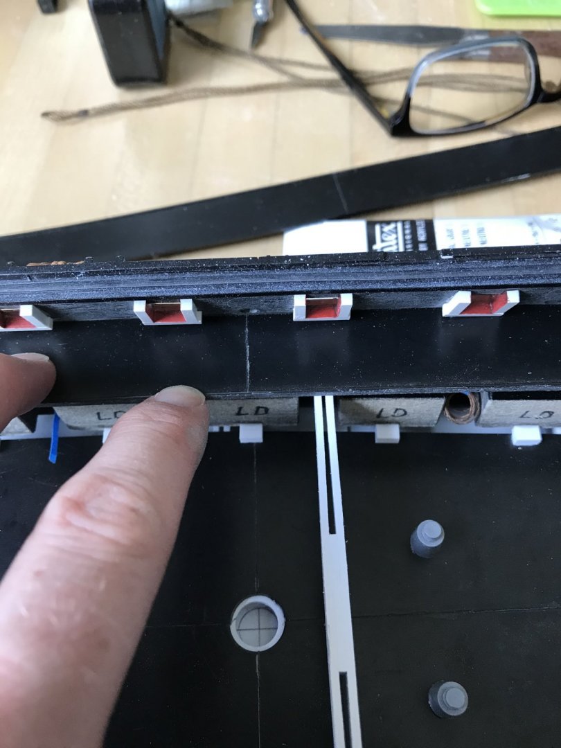
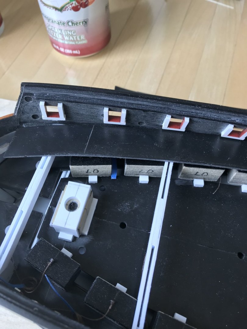
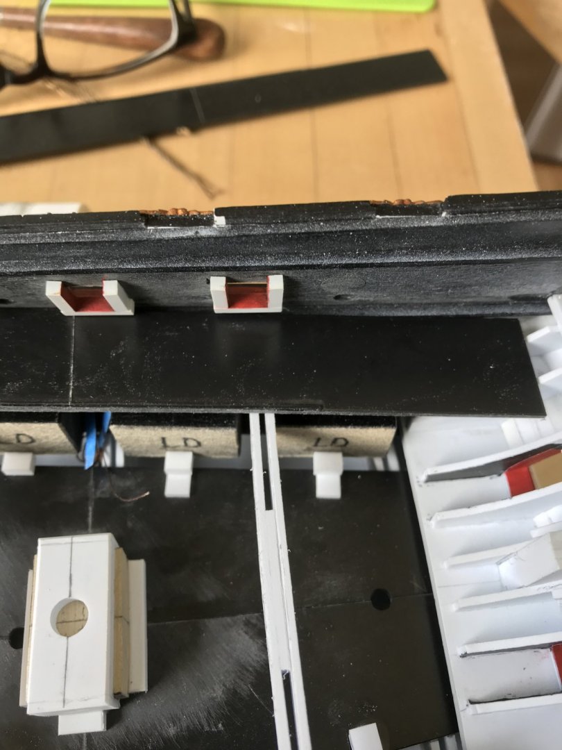
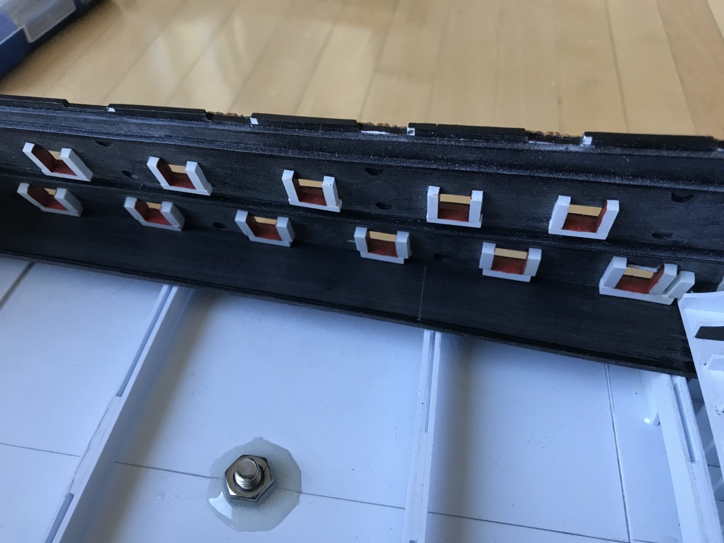
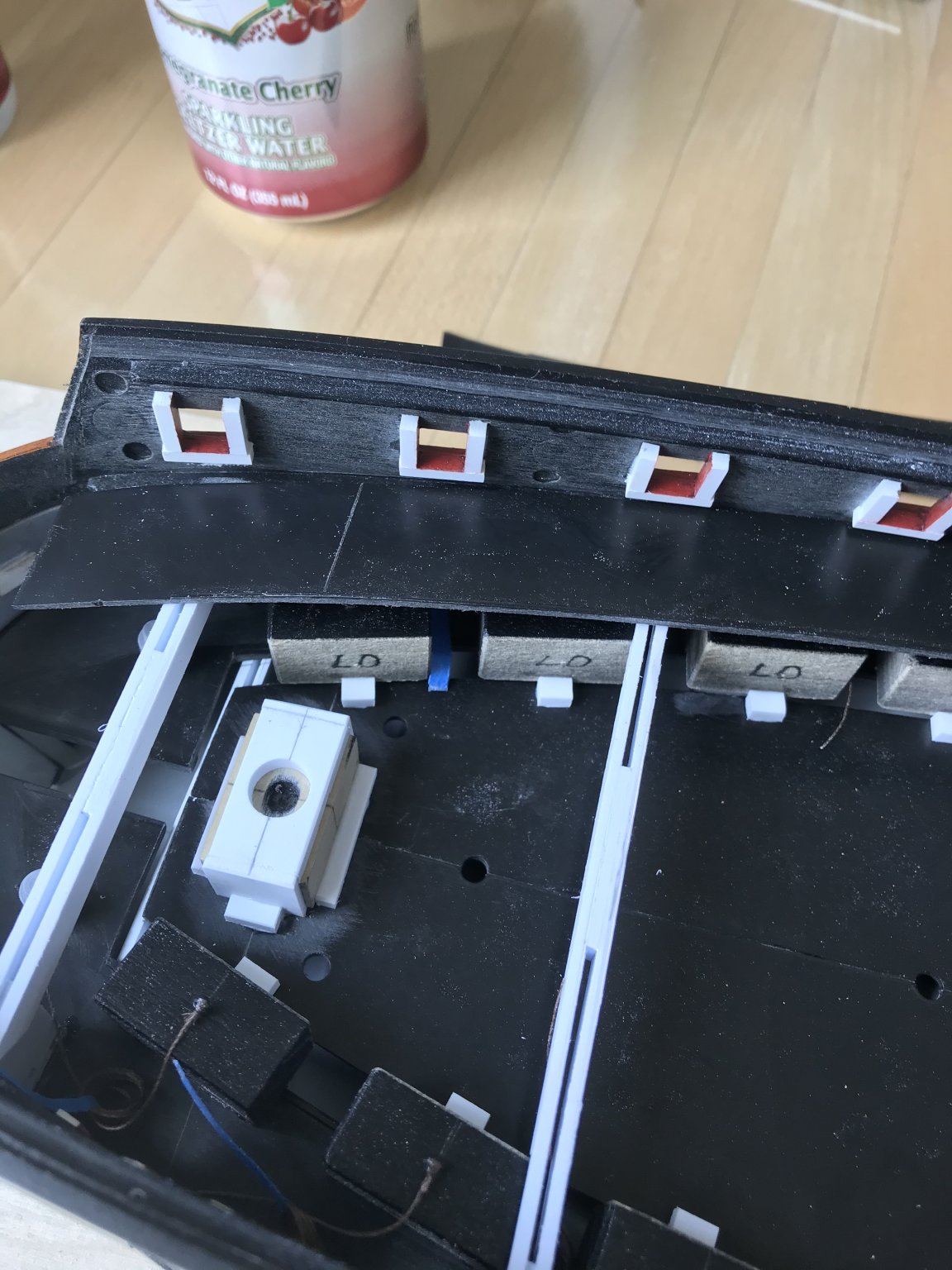
Okay, no problem; I simply shimmed each dummy carriage with a length of 1/16” styrene. In the following picture, you can see these shims (on the left row), which I’ve blacked out with permanent marker, as well as the annealed wire eyelets I made for the port lid laniards:
The other little surprise that I failed to calculate was the sheer length of the lower deck gun barrels, after cutting off the cascabels. My Initial plan was to butt my blocks up against the slight raised lip of the carriage decking, and that would determine the outboard projection of the gun barrels. The trouble is that would place the trunnions (which had been shaved off) and the dolphin handles outside the hull!
Instead, I discovered that I could place the dummy carriages a little further inboard, so that the new 1/16” shim butted up against the raised lip of the platform decking. This provided me with the extra real-estate I needed for a reasonable projection.

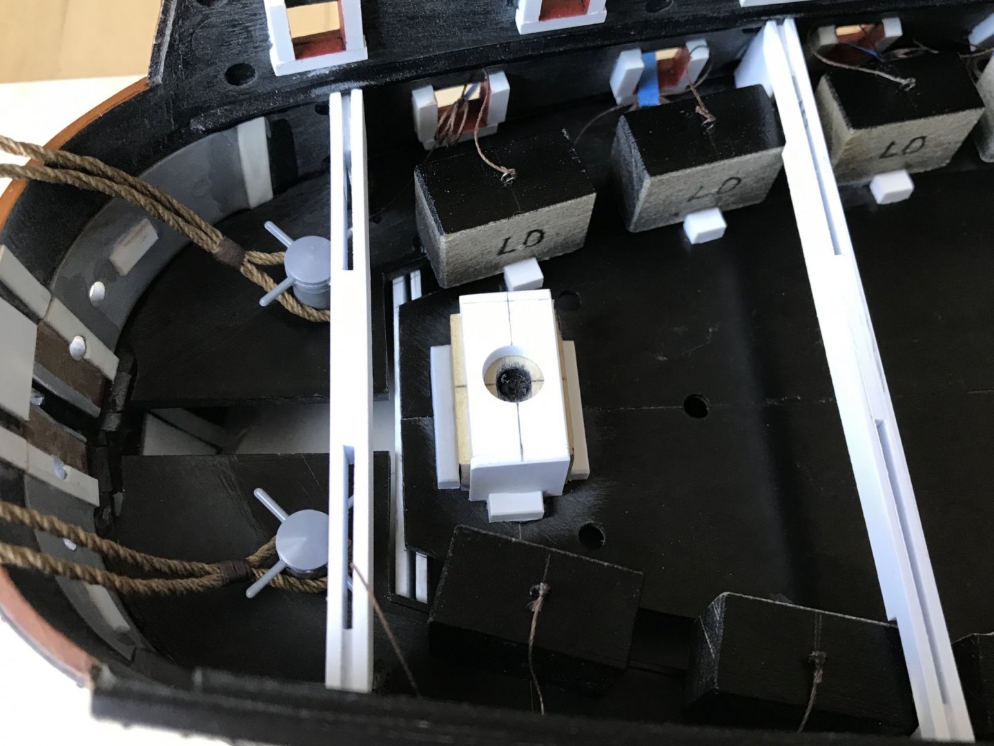
I wanted, however, for there to be a little extra support for the carriage blocks, so I made small outrigger blocks that I’m in the process of gluing to the inboard edge of the carriage platform decking.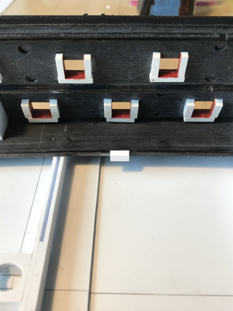
There is a generous 1/4” gap between these outboard gun platforms and the inboard central decking that supports the masts. When it comes time to secure the dummy carriages, they will be cyano’d in-place to both the decking and the out-rigger blocks.
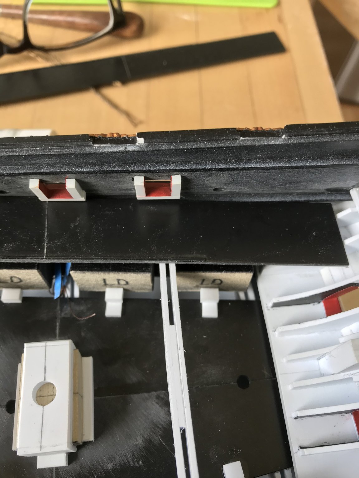
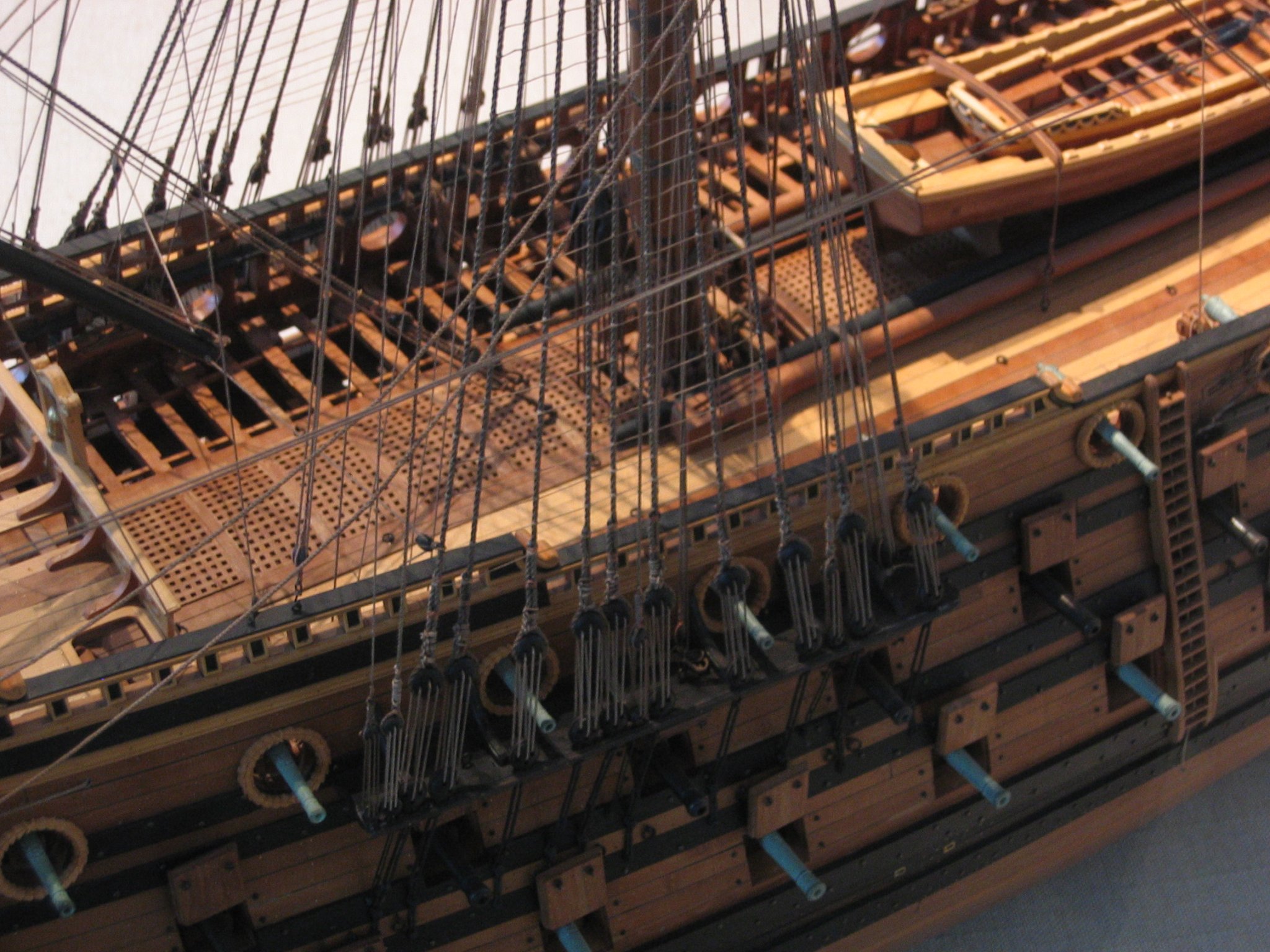
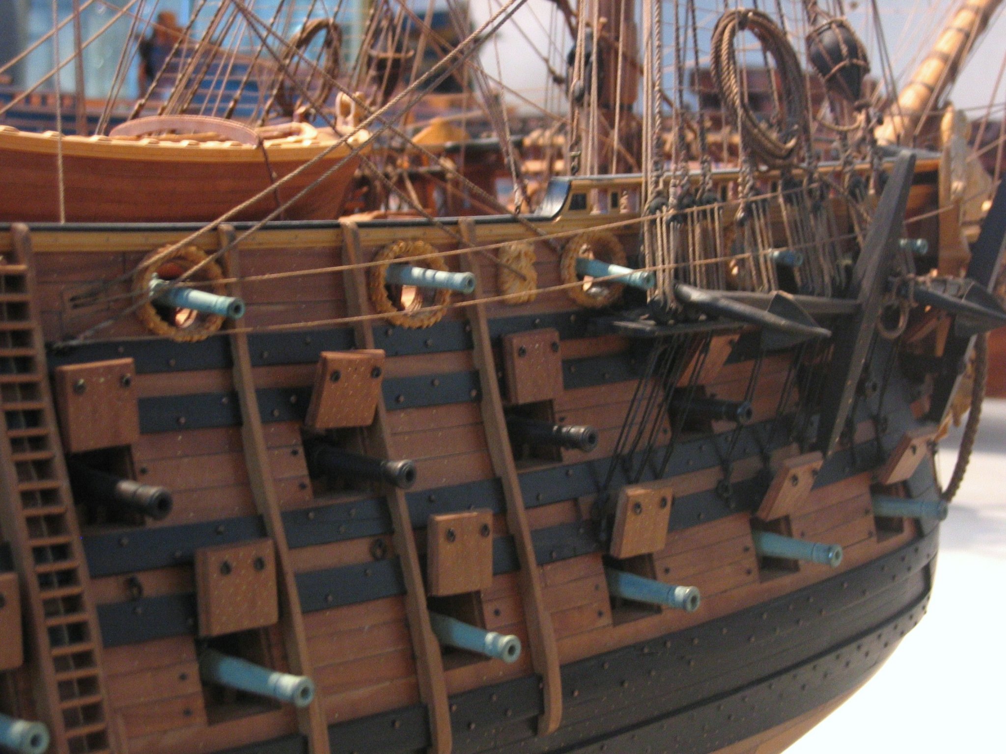
While I won’t glue-in the gun barrels until the model is rigged and nearly complete, here are a few shots that show what that projection will look like:
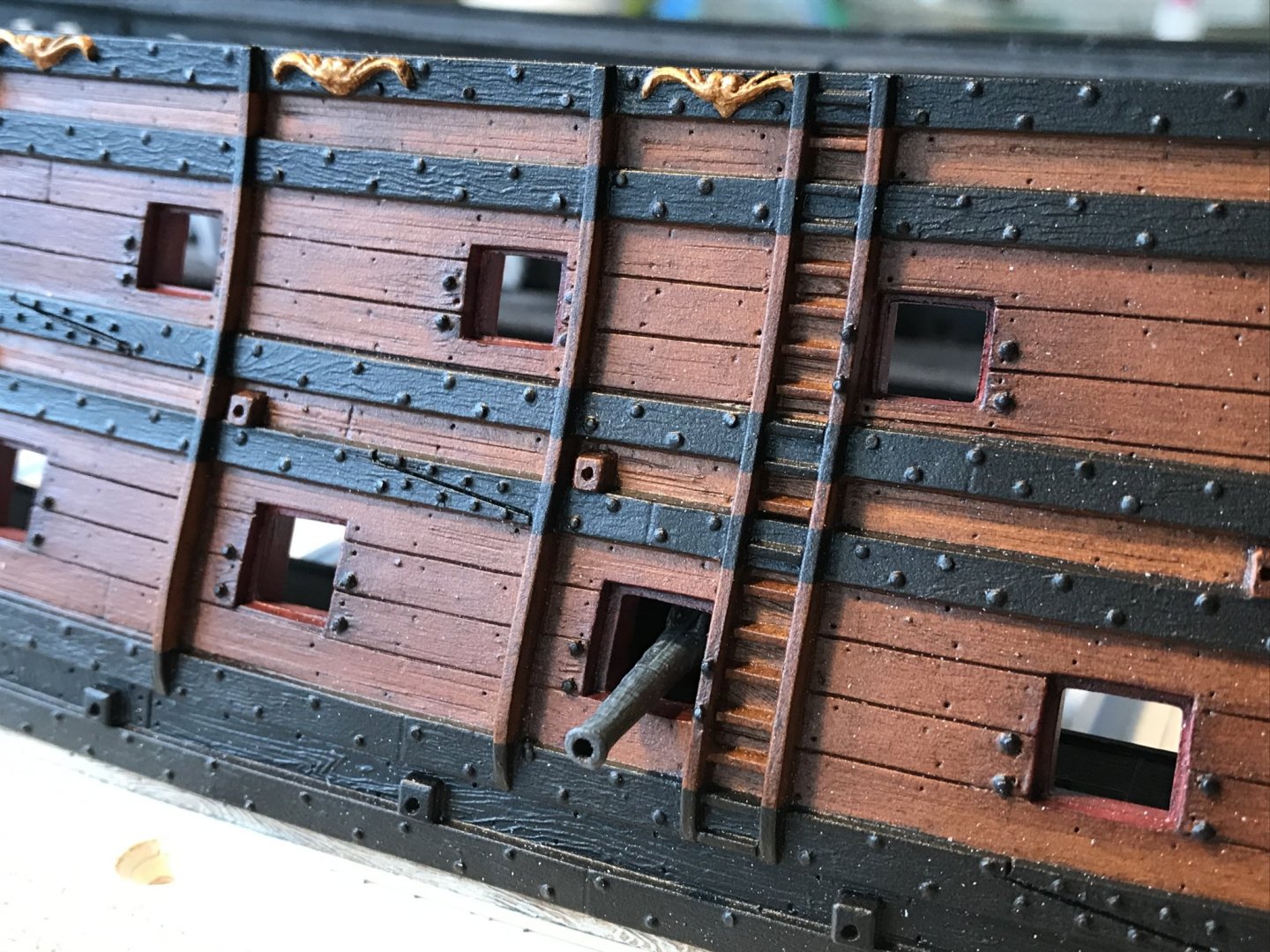
I think that my efforts to increase the breadth of the cannons provide a better sense of heft and scale than would otherwise be the case.
So, that’s where the work is heading. I still have a fair amount of repetitive work to do before I can place the middle deck beams. I won’t get much beyond that, though, because I need to buy some appropriate anchor cabling from Syren, and it may be a while before Chuck is filling orders again.
Anyway, if I get stuck, I’ll turn my attention to constructing the quarter galleries from the lower finishing, on up.
Thank you all for checking in on me, and your well-wishes during my recovery. I’ve had some relapse of symptoms - which is apparently common - but nothing concerning. I’m going to be just fine.
Until next time, stay well and close to your loved ones.
-
-
Guys, thank you all so much for your concern and well-wishes. Today is the fourth day since I started feeling sick, and I already feel pretty much myself; no more fever/sweats/chills, no more headaches/body aches, no more weird chafing skin sensations, no more sinus congestion. I still can’t smell anything, but if that’s the worst of it, then I am well ahead of the curve. I am extremely lucky!
EJ, to answer your question, I will not be doing any special detailing or paint work on the interior. The gun mounting blocks are painted flat black and are wide enough to close off any view inside because there is a fair amount of structure supporting the middle and upper decks. You really can’t even see much around the main hatch gangway, as the double ladder takes up most of that space, and the grating openings are very small.
I will probably have someone seated in one of the stern chase ports, and reaching out toward the trailing launch as supplies are passed up to him.
Where I will spend some time is building out at least the facade of the galley stoves beneath the forecastle deck. And I will also represent the hanging knees that would still be visible under the overhang of the forecastle and quarter decks.
It would be nice to trick out the whole thing, but my process and insistence on certain things is sloooooow. Nevertheless, I would like to finish this model, at some point. I’ll save all the bells and whistles for my true magnum opus.
I was marveling, the other day, at Ab Hoving on Ships Of Scale, as he laid-out very straight-forwardly his card modeling process. This time, he’s building a Dutch mid-rate frigate while simultaneously building three or four others:
Ab doesn’t seem to take it to quite the level of detailing as Doris, for example, but the ships he creates are fantastic looking. He starts with good and accurate lines that his research background helps him to ascertain, and then his process is very quick. He uses the same distressing protocol as Herbert Tomesan, and the finished result looks highly authentic.
I’m happy with what I’m doing for a variety of reasons, but the speed of Mr. Hoving’s methods is very seductive.
- shipmodel, GrandpaPhil, ccoyle and 5 others
-
8
-
I thought that medicinal scotch was shielding me from the Corona virus. Apparently, not even scotch is strong enough to keep it away. So, I am at home full-time, now, for at least the next two weeks. I am very lucky that the worst of it seems to have been fever and body aches although, interestingly, I did lose my sense of smell.
And, so, work on Soleil Royal continues, more or less full-time now.
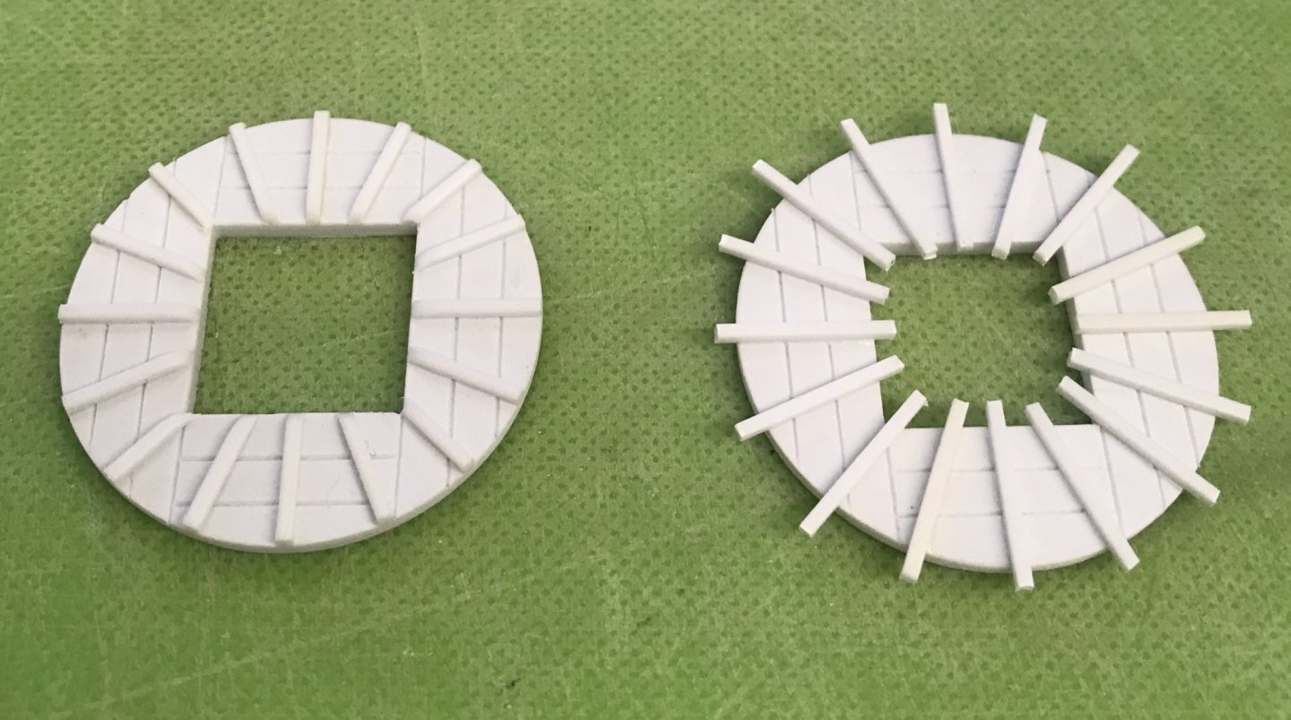
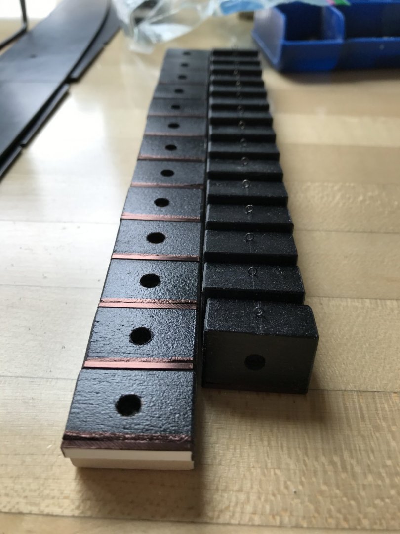
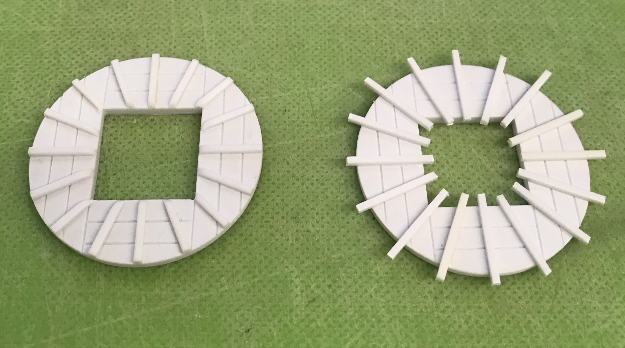
Thanks to Henry, I was able to finish modifying my gratings. Here’s a shot of the new cambered gratings as compared with the stock, flat gratings:
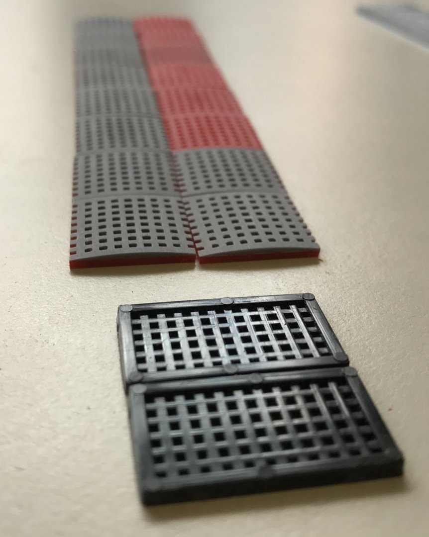
I will be making new combings for these when it comes time to install them.
I also wanted to finish detailing the fore and main masts. One of the peculiarities of the Heller kit is this groove that they let into the masthead, for the shrouds to pass over. It is unnecessary, though, and creates a weak-point in the mast. Borrowing a page from Dafi’s Victory log, I decided to fill it in with a strip of thin styrene and medium viscosity cyano:

Next, I wanted to file-in a tapered profile to the hounds, which are parallel-sided on the kit:
This alteration is more evident on the foremast, as seen above left.
Then, I could define the bibs as distinct from the hounds:

I added in the nailing of the hounds, and I also filed a slight taper to their aft edge, to give them a little extra shape:
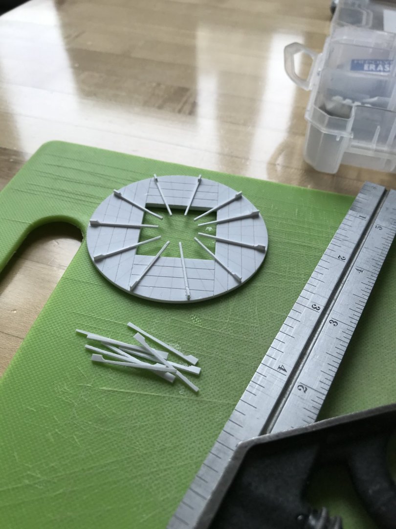
Satisfied with the lower masts, I also wanted to complete my main top, just to get a sense of that process, since I need to make three more of them.
After marking out my ribs, and separating them into rough blanks, I used a simple two-step jig to cut the long, bottom edge to it’s still oversize width, and then the short top edge to height:
As a note for the future, I would be wise to really hone my 1” chisel back to a razor-edge, before doing this again. The slightly dull edge caused the plastic to cleave, rather than cut cleanly, and I was left with many ribs that had skewed bottom edges.
In the next step, that necessitated filing them square before gluing them in place:
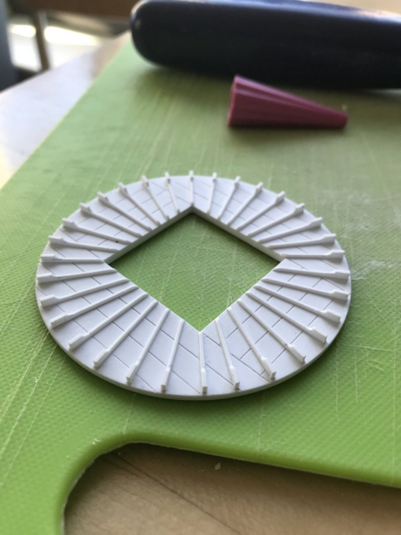
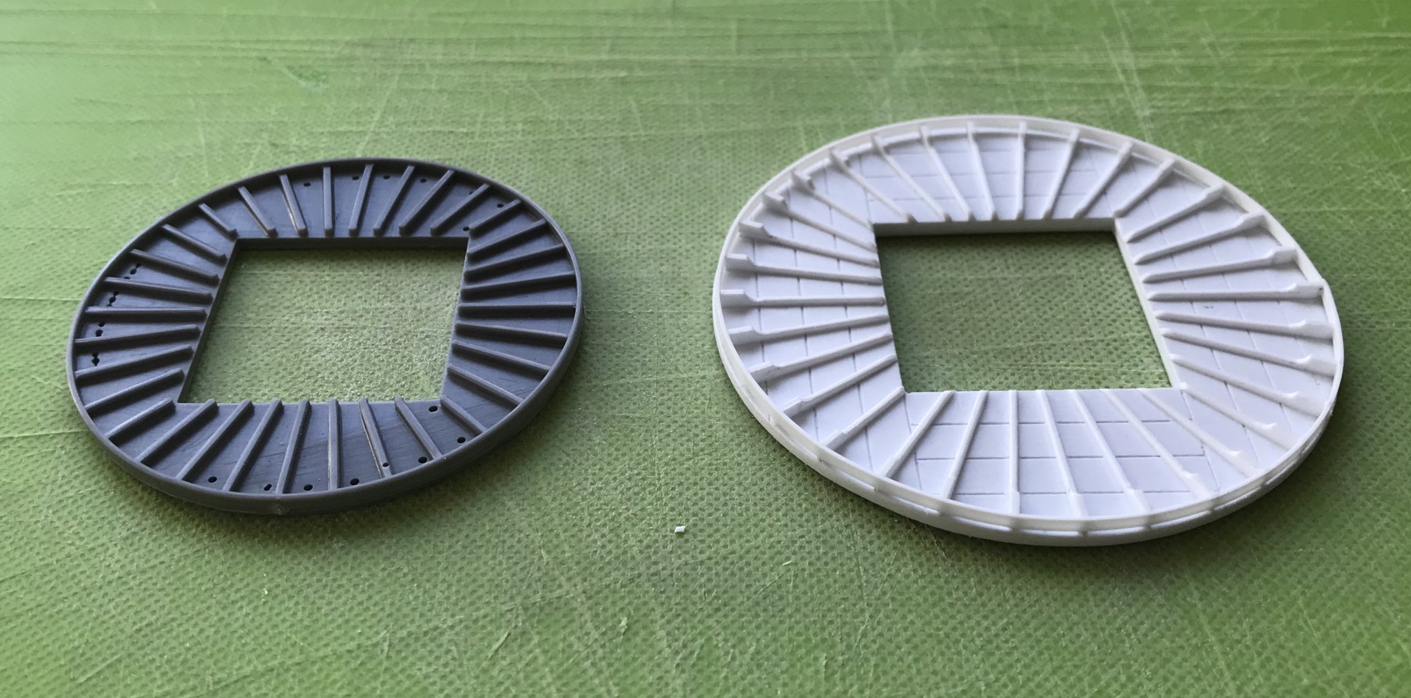
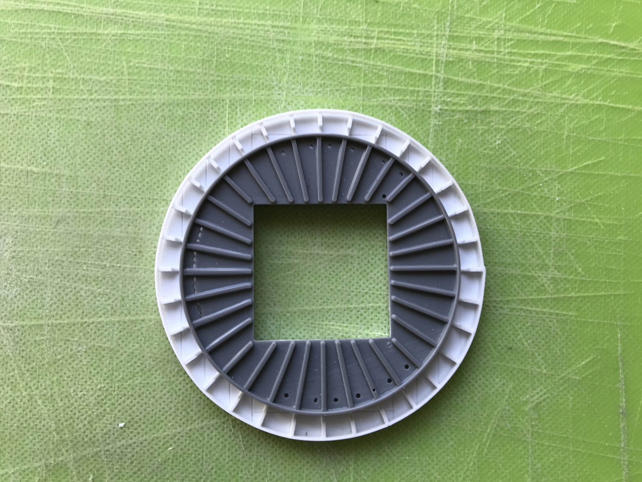
Finally, with the ribband strake circling the top, here are a few comparison shots with the stock main top:
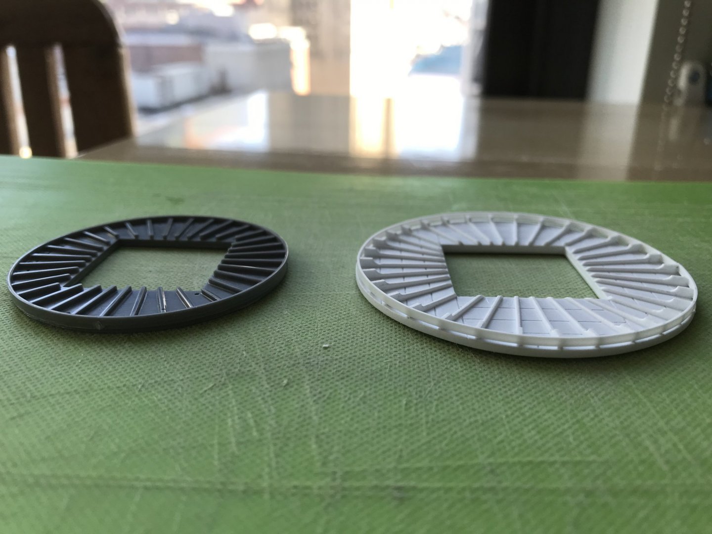
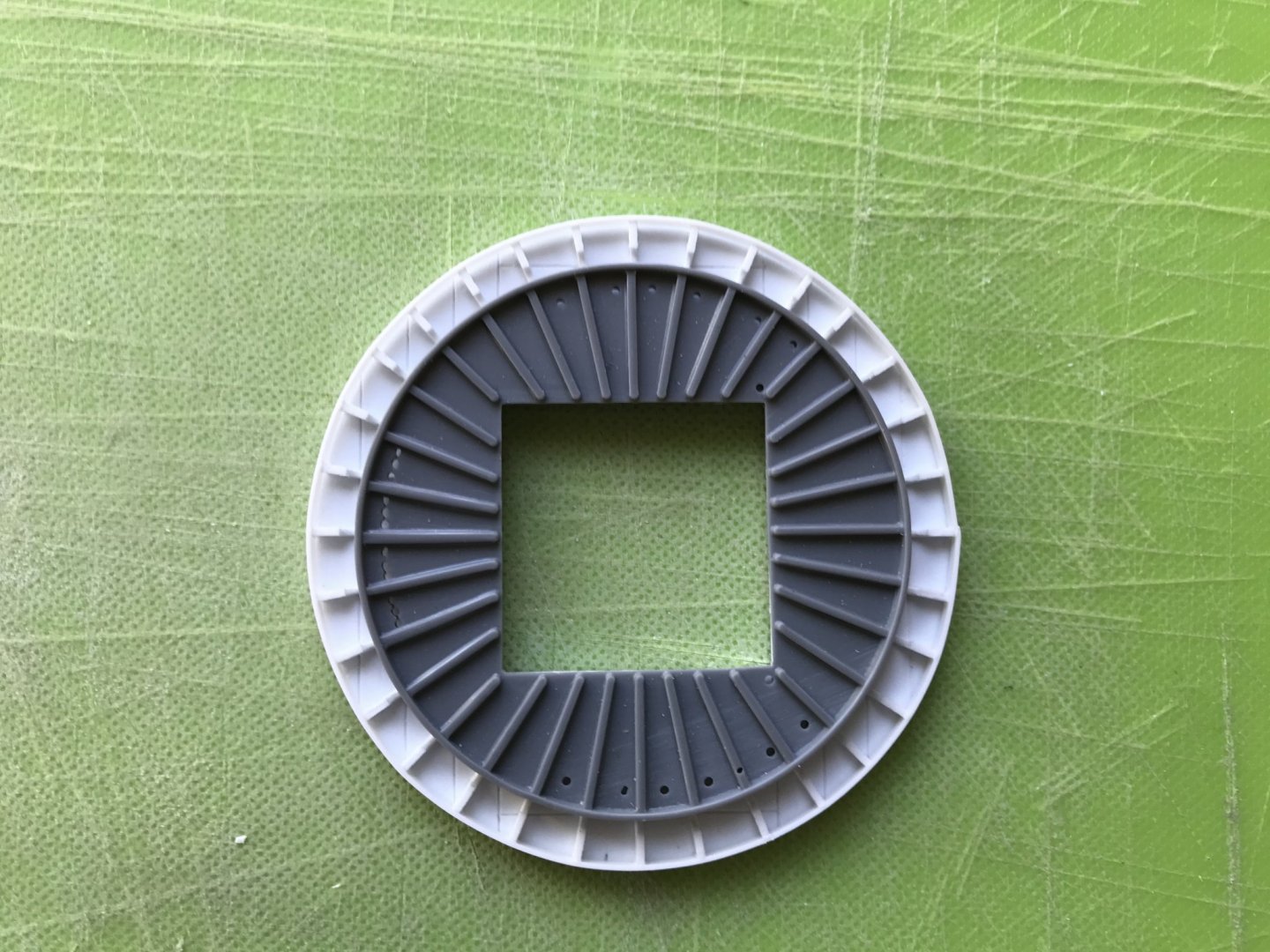
My version is significantly bigger, but it will now give a better spread to the topmast shrouds. And, here’s the top on the masthead:
All-in-all, this was a significant amount of work, but the improved scale and detailing make the process well worth it. I can tweak the rib process a little to speed it up, so the others shouldn’t be as time-consuming.
Next, I boxed-in a footing for the main mast:

And, then I got to re-scribing the gun platforms to the inner hull. As a reminder, I had taken the stock lower decks and separated each deck half into an inner and outer component. This way I could re-cycle AND accommodate the increased width of the hull.
It was surprising to me just how much scribing I had to do to get a good fit against the hull. Evidently, cutting away the lower hull relaxed what was left above, into a somewhat flatter-sided ship.
It wasn’t strictly necessary to achieve a close scribe, here, but I want maximum connection for extra strength and rigidity.
That’s all for today. Thank you all for your likes and interest. Stay safe, everyone.


Soleil Royal by Hubac's Historian - Heller - An Extensive Modification and Partial Scratch-Build
in - Kit build logs for subjects built from 1501 - 1750
Posted · Edited by Hubac's Historian
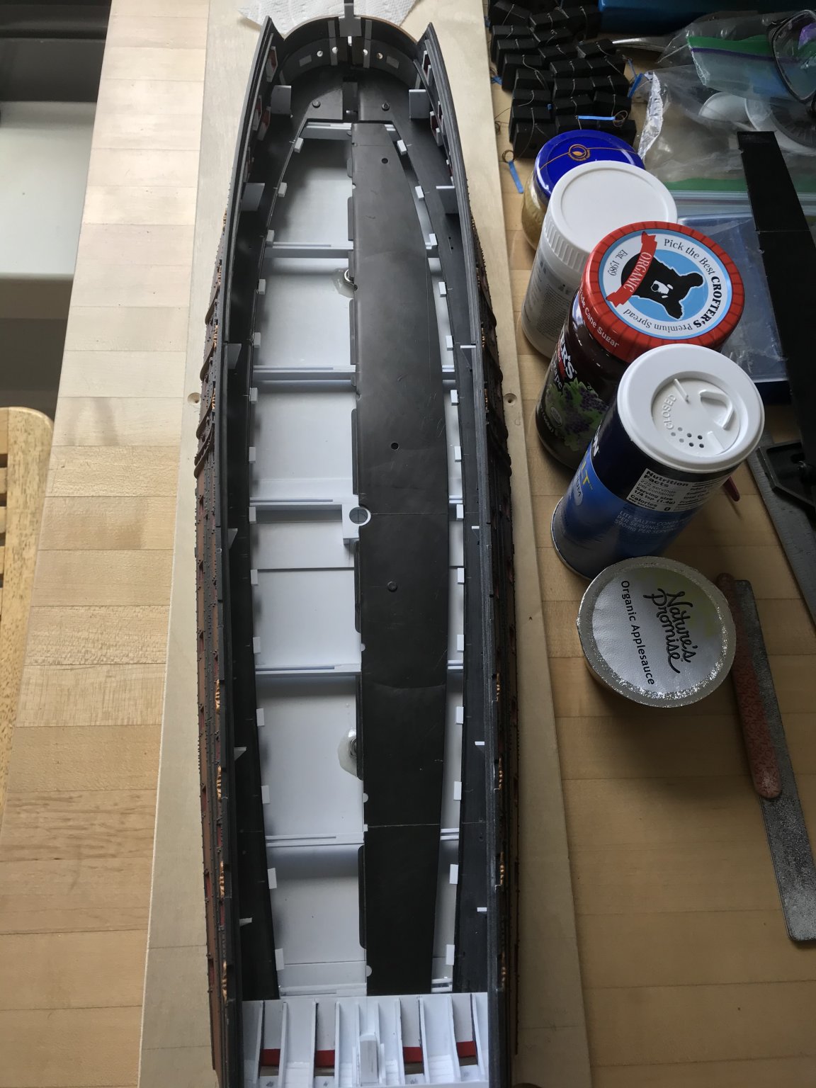
Work on the middle deck is coming along nicely.
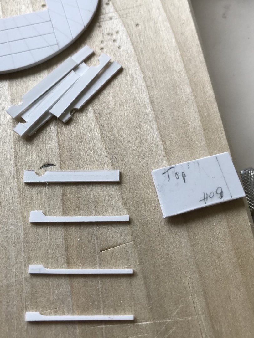
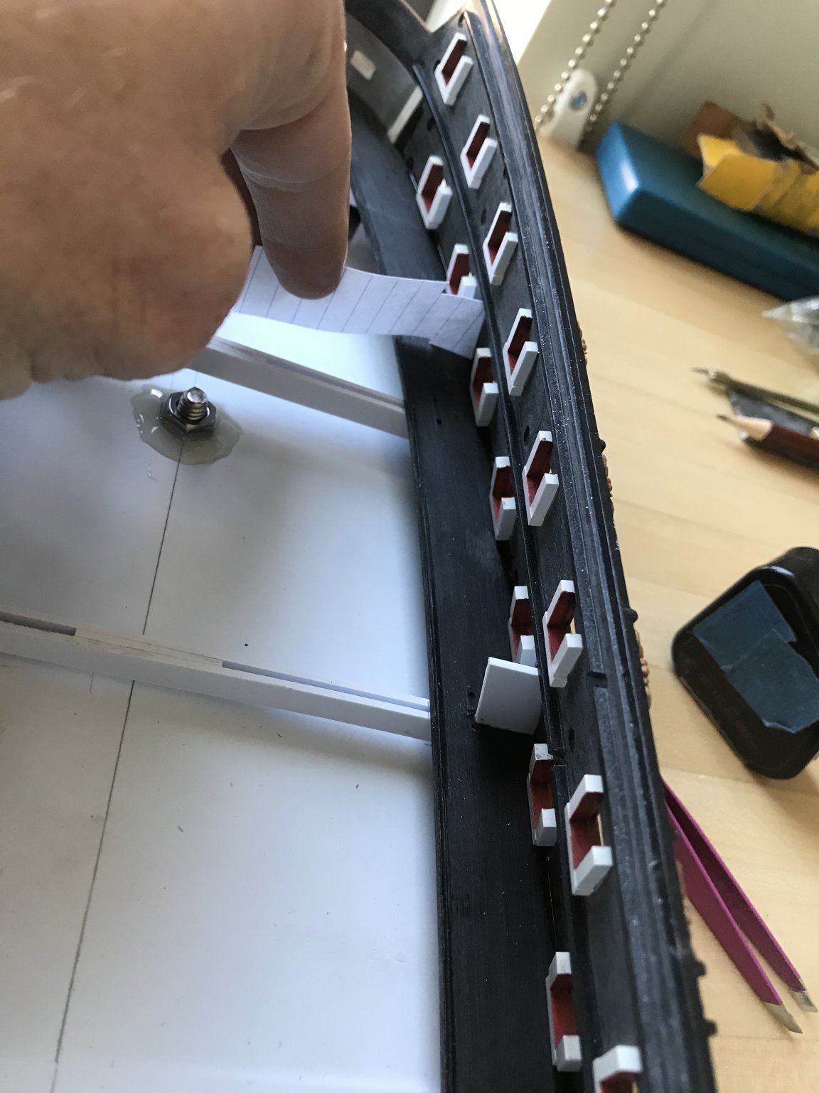
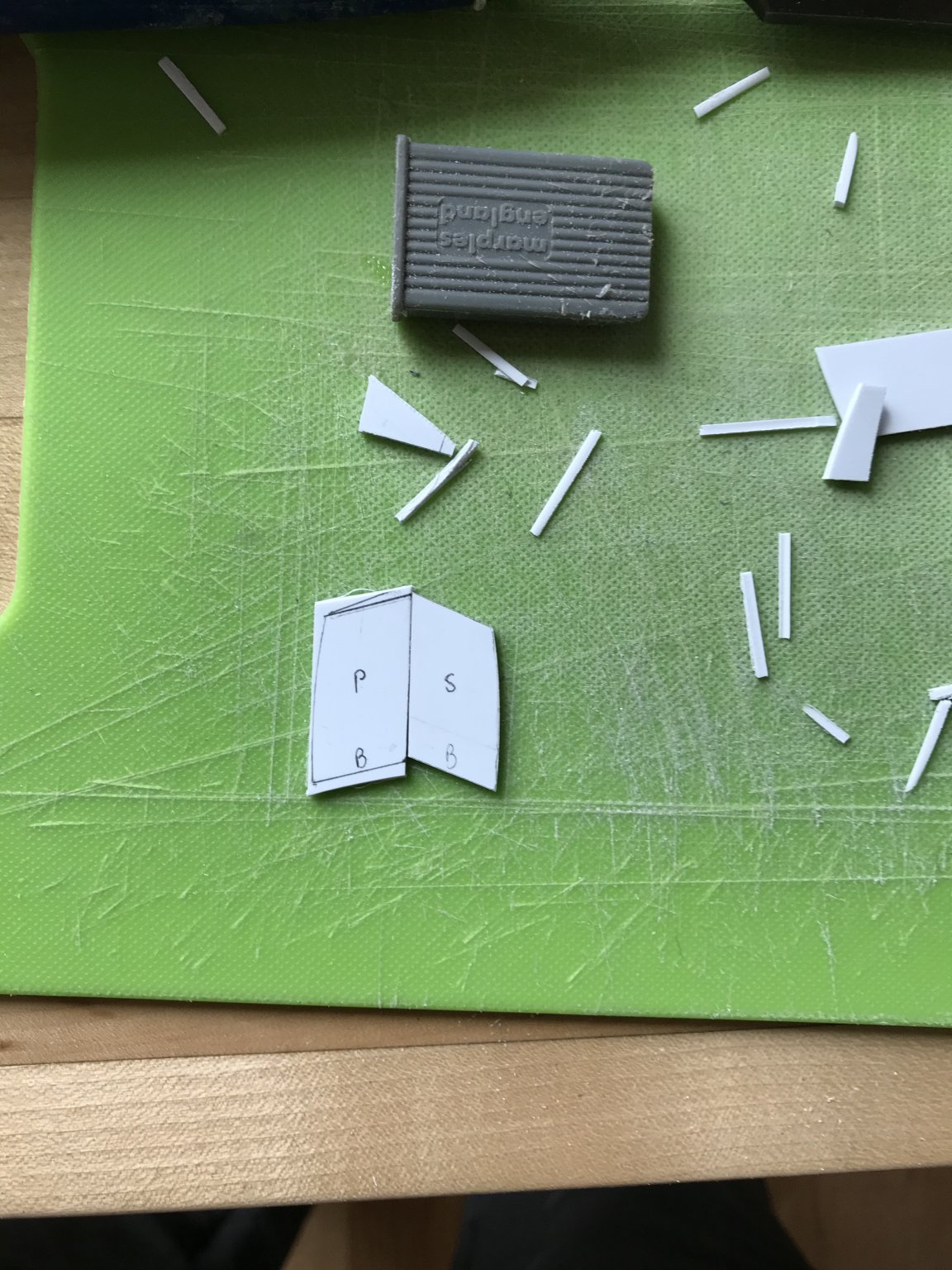
As mentioned, earlier, I found it much simpler to re-make the dummy carriage platforms from scratch, in order to achieve a close scribe without sacrificing platform depth. I used this simple scribing method to arrive at a faithful pattern for each side:
You can see the relative flattening of the ship’s sides, here, with the new pattern mapped-out on white styrene:
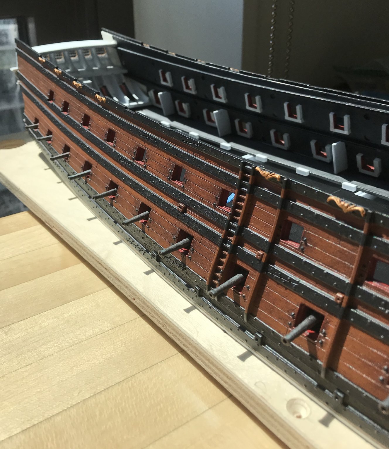
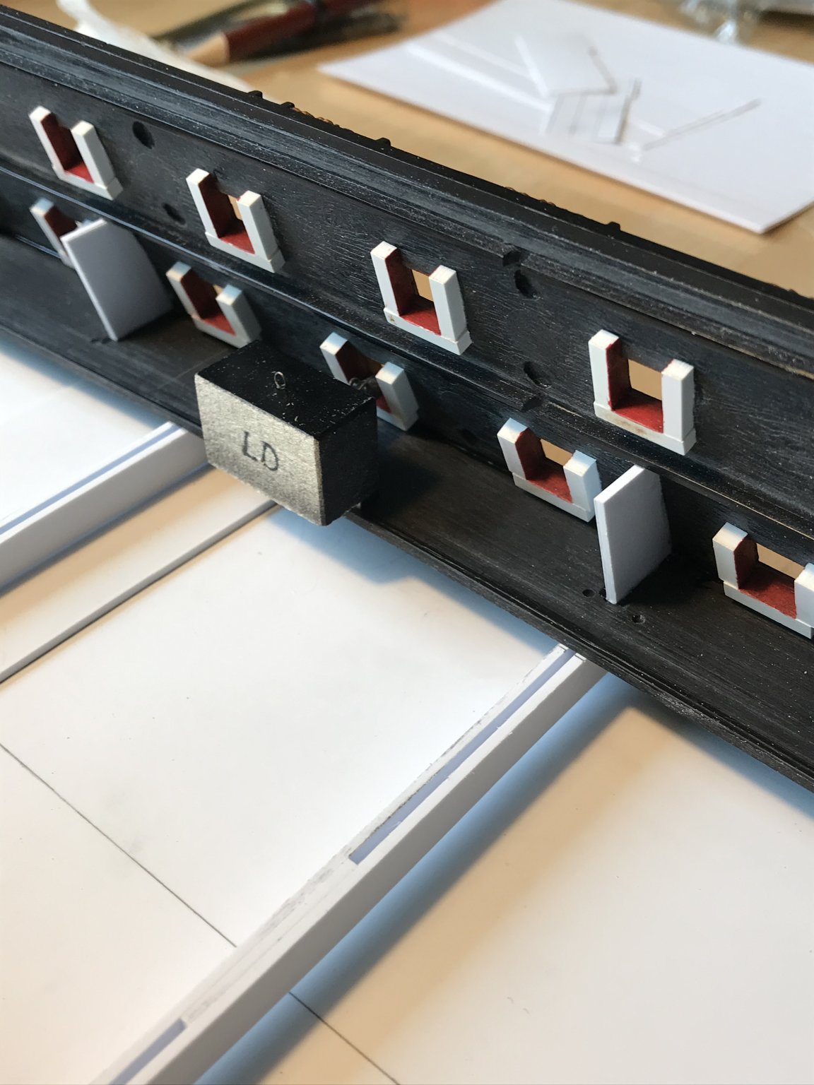
Once I had achieved a close scribe for each side platform, and before gluing them in place, I checked for the ideal positioning of the dummy carriage blocks, along the whole broadside. On the lower deck, my blocks all follow a uniform line, as they all butt-up against a raised lip at the back edge of the platforms.
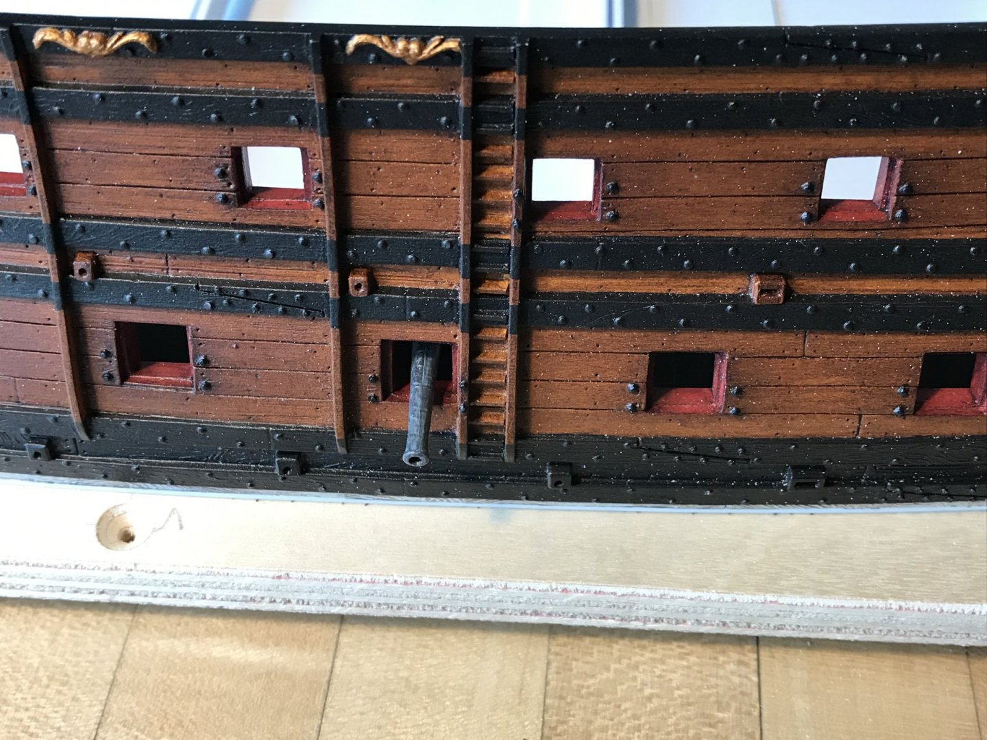
The middle deck presents a somewhat different reality, as the outward re-curve of the hull, in the area of the anchor lining, would make the barrel projection seem too short, if I were to simply place all of the dummy carriages at a uniform distance from the port opening. How’s that for a run-on sentence?!
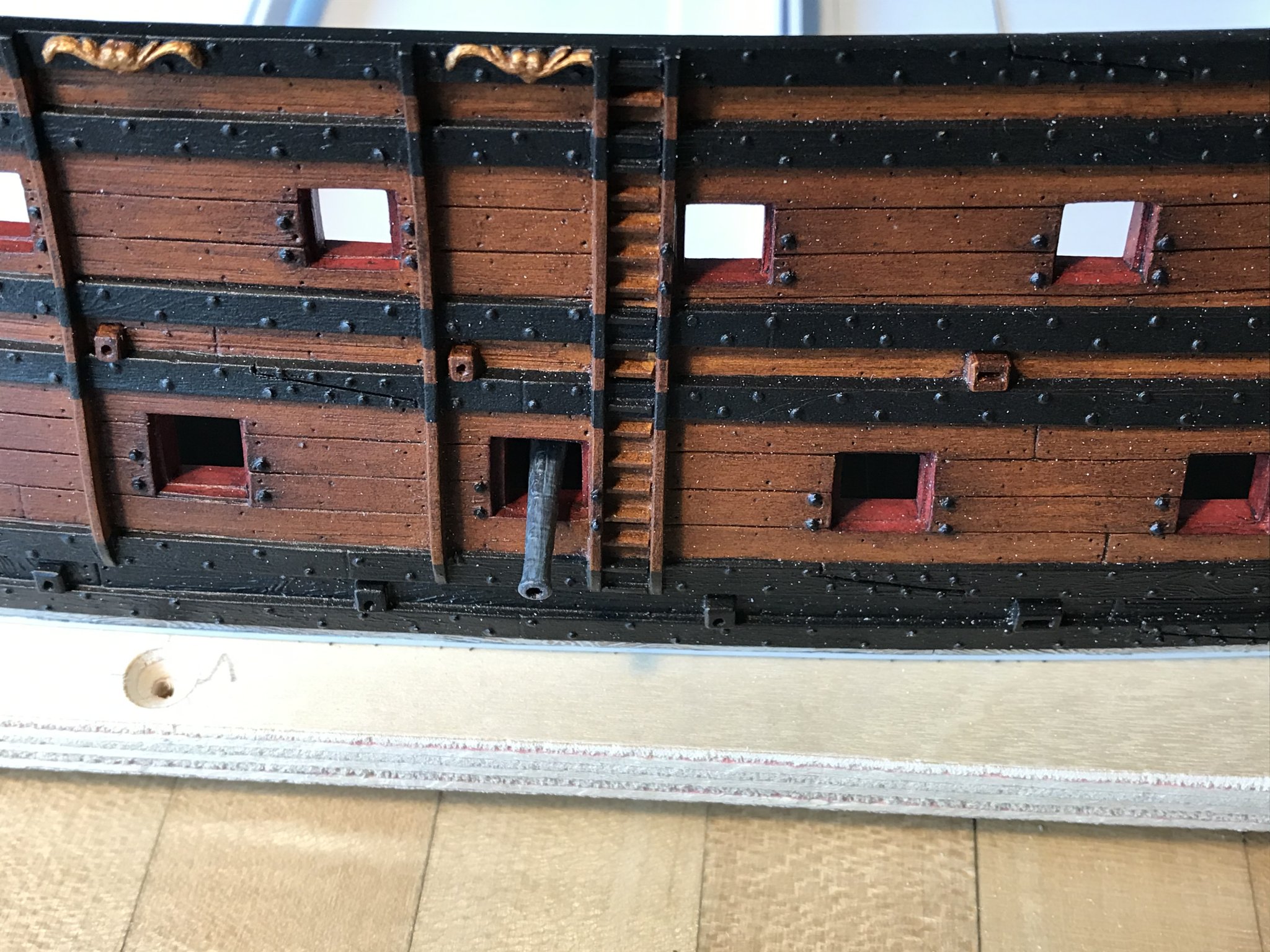
So, testing the depth from port to port, I discovered that the forward 5 dummy gun carriages needed to be staggered closer to the port openings in increments up to 1/16”. Splitting hairs? Yes. The result, though, will be a finished projection like this, relative to the lower battery:
The added benefit of remaking the side platforms is that they are deep enough to adequately support the carriage blocks without any supplemental blocking.
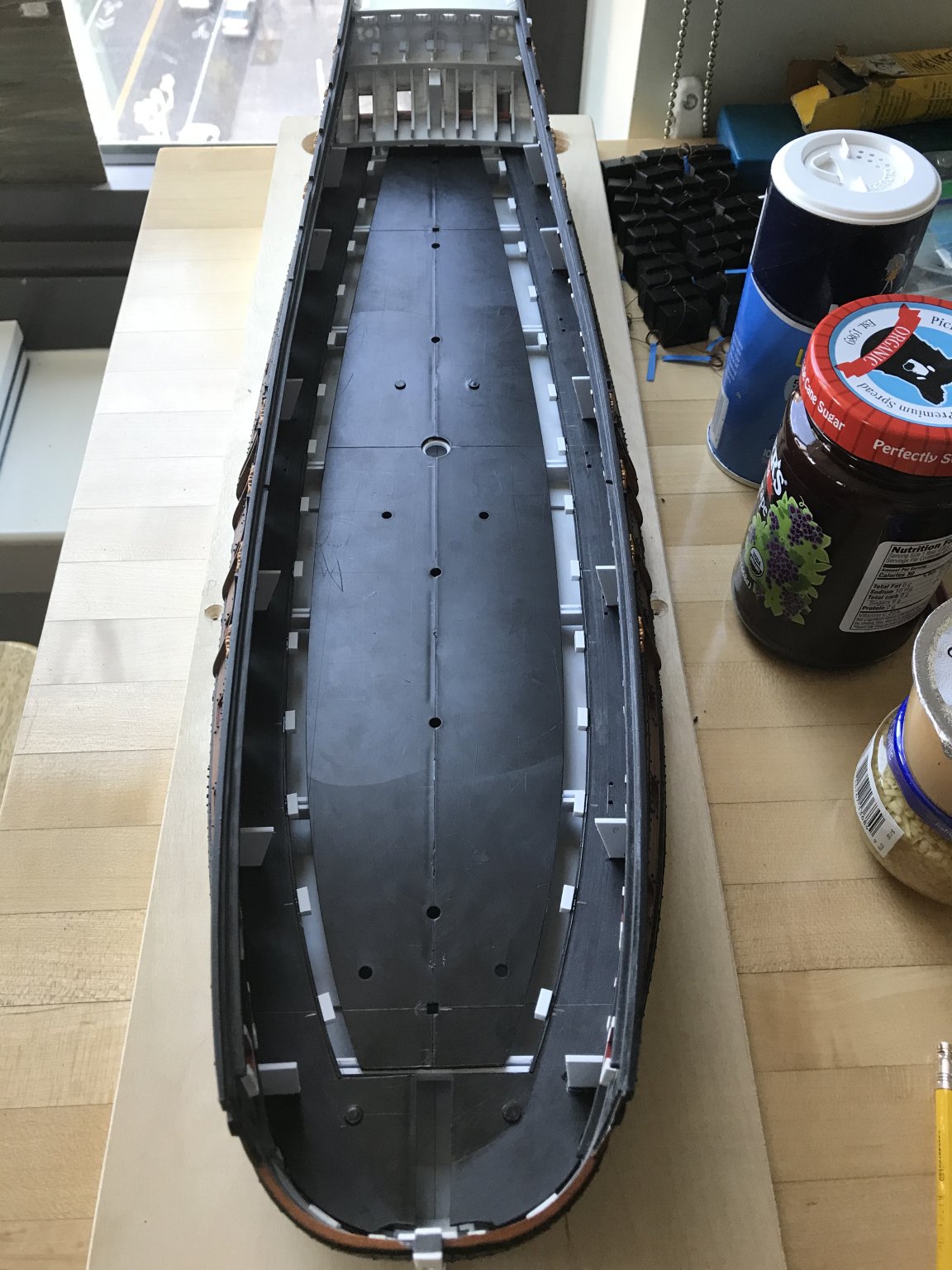
With all of that settled, I glued-in the side platforms and center deck sections, as before - taking care to consider the next step of raking the masts.
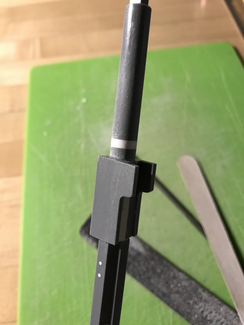
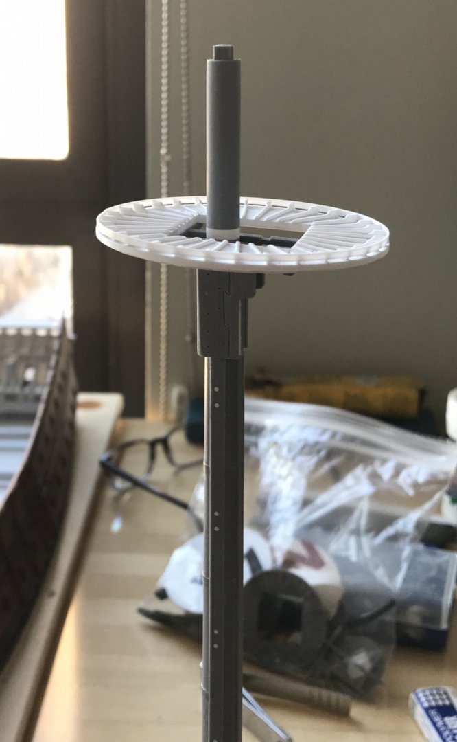
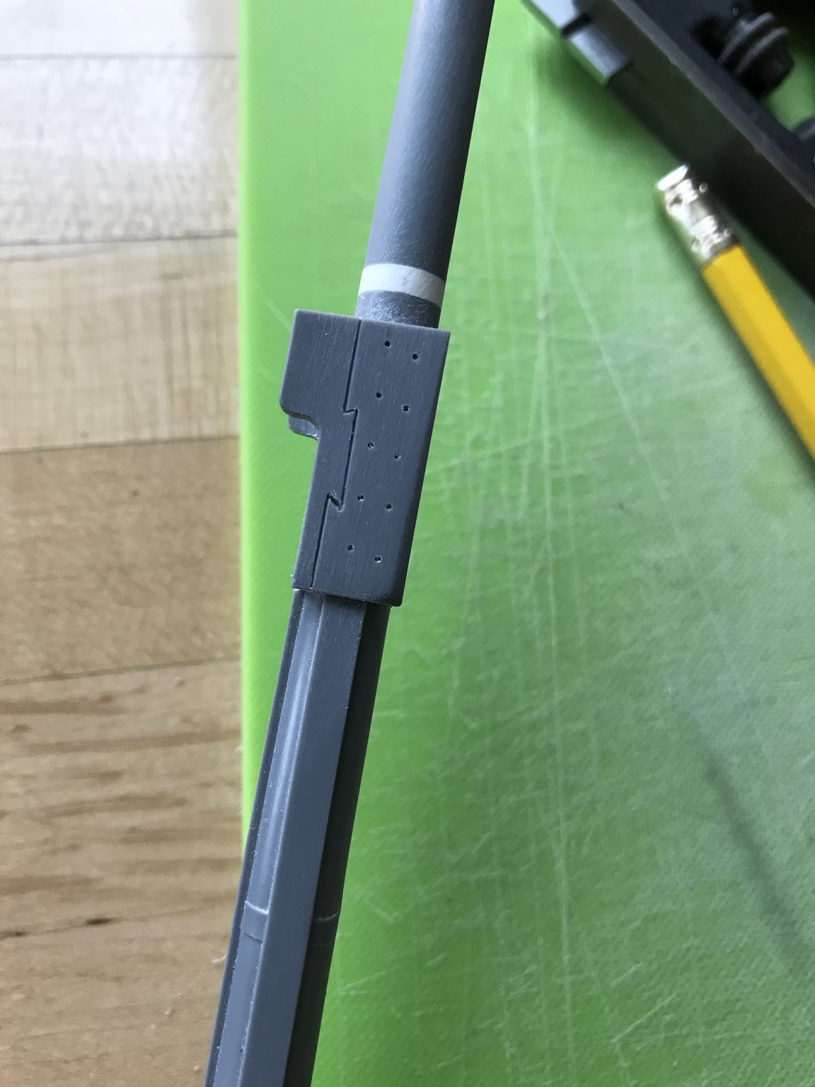
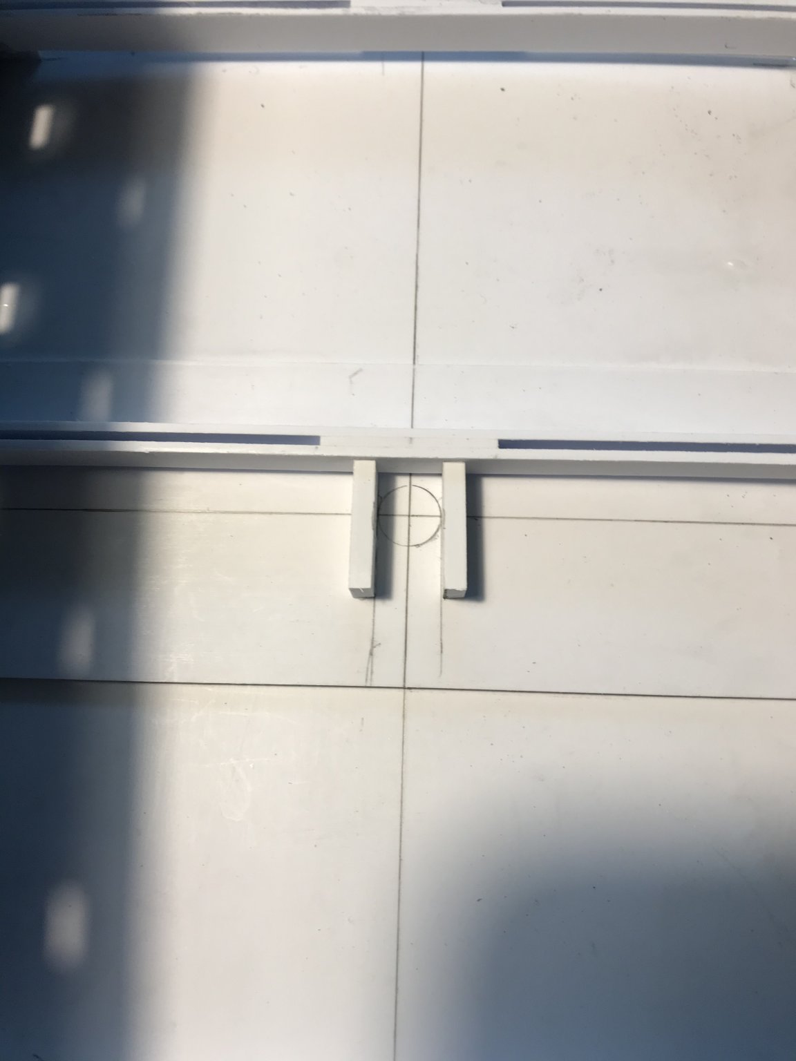
Again - because the masts have been raised, their tapered lower diameter no longer corresponds with the openings at each center deck section level. My solution is to make mast plates that will enable me to align each mast on the ship centerline, while also establishing the rake.
With Lemineur’s masting plan of the St. Philippe at hand, I set the rake for the foremast as nearly perpendicular to the waterline as eye and square could ascertain. I will still have some wiggle room to adjust the foremast, if necessary, at the main deck level; the foremast step is not even an inch below this first mast plate, and the fit is deliberately just a hair slack.
The main mast is raked aft so that the main top is sensibly level to the waterline, while also accounting for the upward trajectory of the top and t’gallant masts.
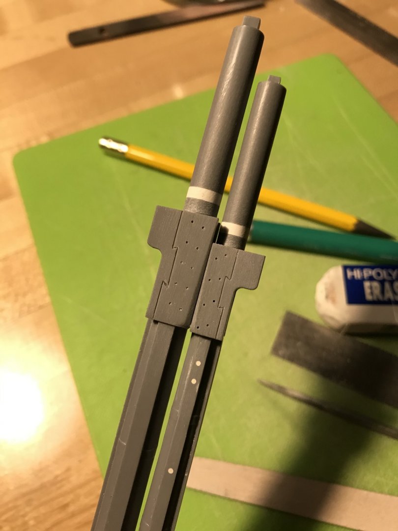
Here are the relative layout of mast rakes and top heights from a variety of angles:
Without the upper deck and bulwarks in place to complete the picture, these mast heights may appear exaggerated, but I am confident that this impression will trend favorably as the model continues to take shape.
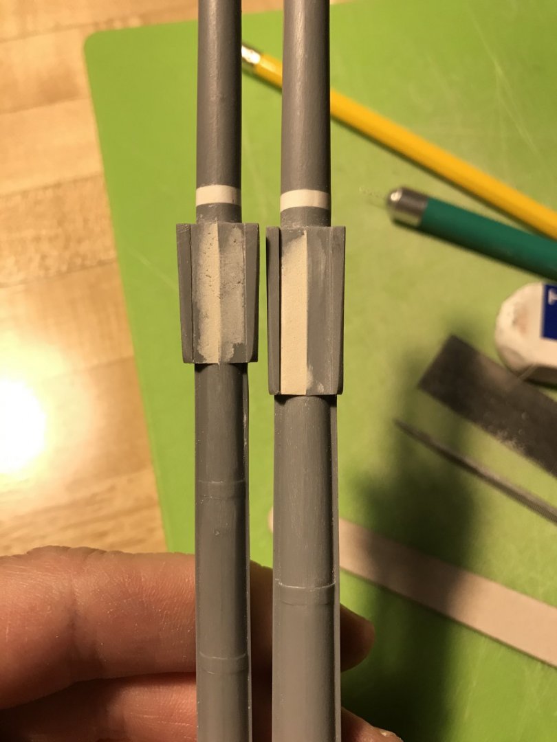
In other works, the sprit, fore, main and mizzen tops are now complete, and I have made up all of the middle-deck dummy carriages - complete with shims for height, and lid lanyards. I will wait to set the dummy carriages until after I have made the gusset supports for the main deck beams.
Placing those beams will require a little thoughtful layout, as they must accurately frame the openings for the main deck hatches and gangway. The beams around the gangway will have to be realistically sided, as they will be partially visible.
So, onward and upward we will go. Thank you for the likes, your interest and for looking in!