


drobinson02199
-
Posts
914 -
Joined
-
Last visited
Content Type
Profiles
Forums
Gallery
Events
Posts posted by drobinson02199
-
-
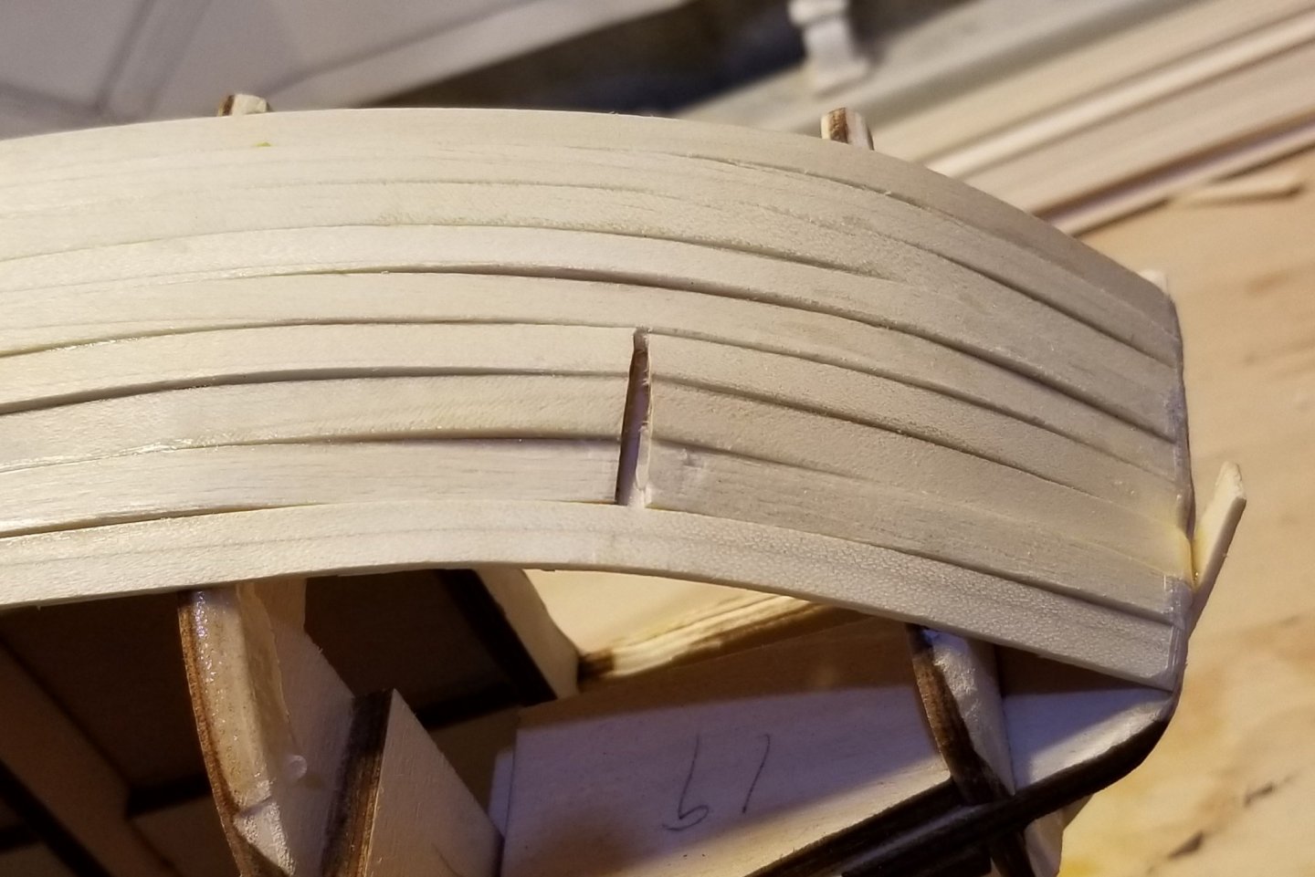
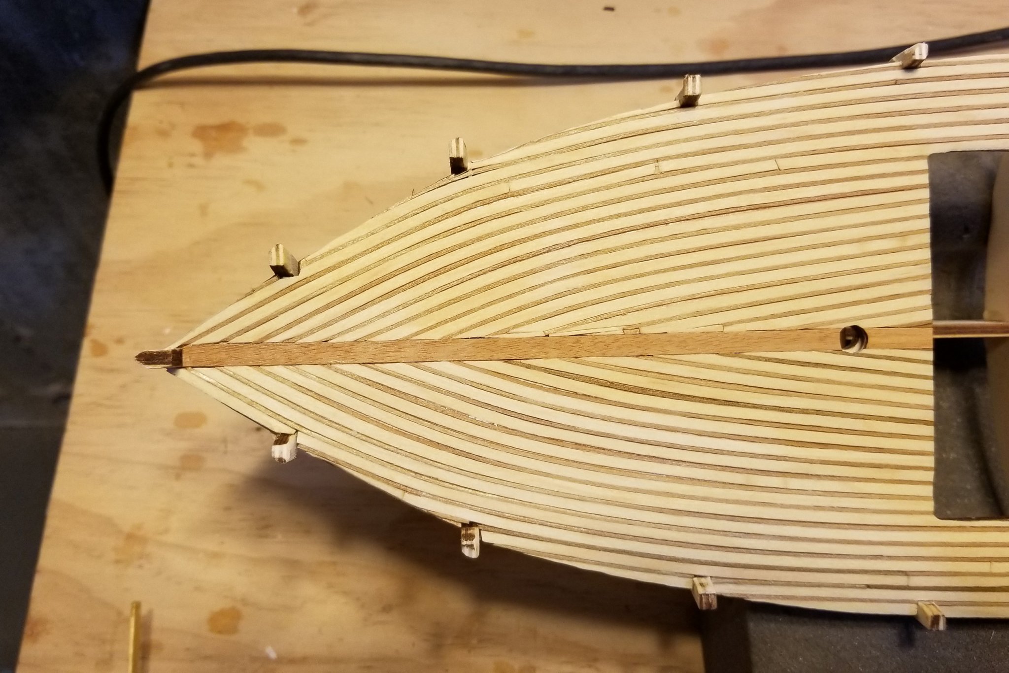
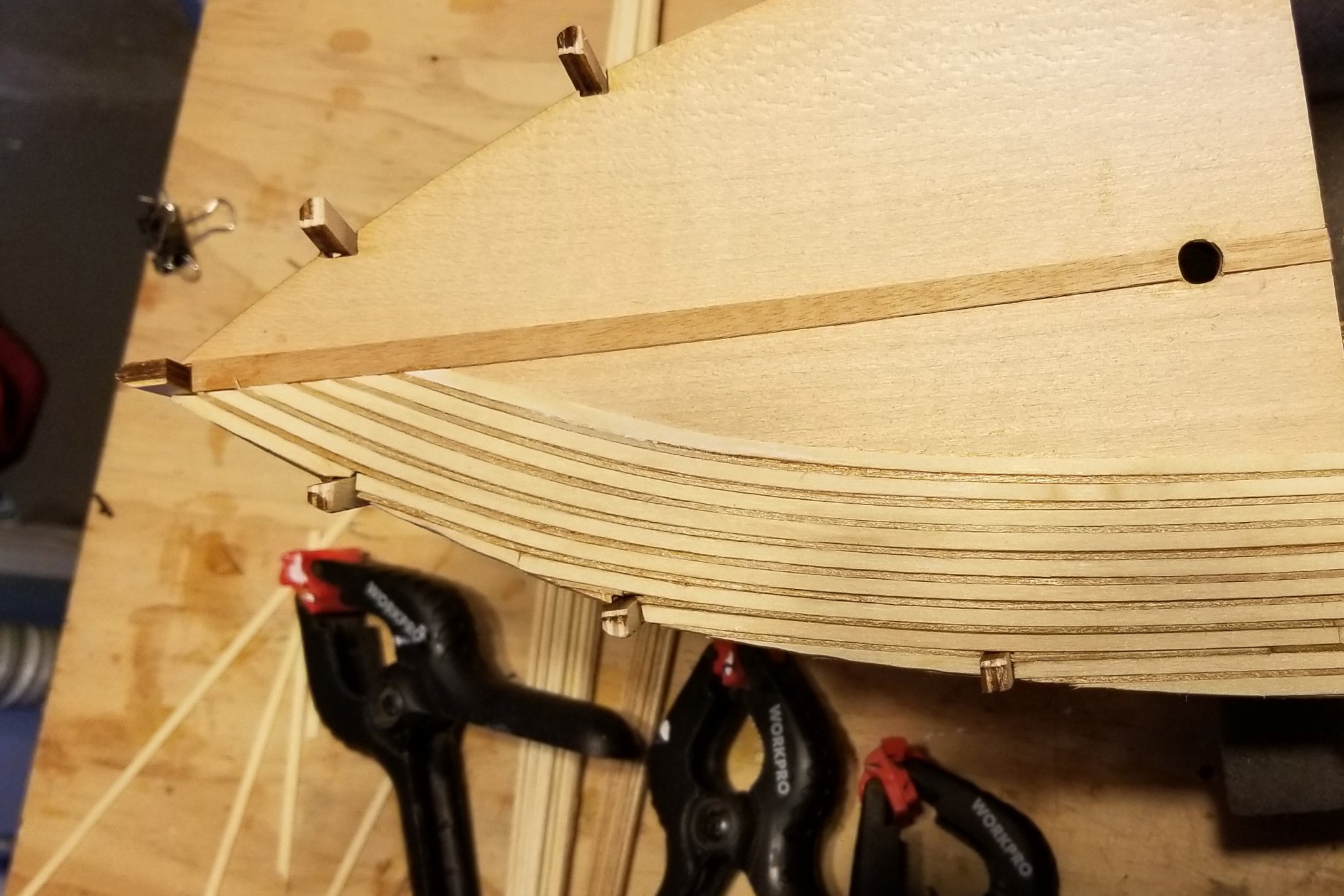
I use a steamer when I'm planking, which gives these basswood planks a lot of flex. I had too much bulge at the stern, so to adjust it I did the following as shown in the picture:
- Used a rotary cutter to make a shallow "V" so that I could bend the whole structure down
- Installed the next plank, steamed the "V" area, and then used reinforcing ribs behind to attach the "V" area to that next plank
- Installed a short length of planking behind the "V" to hold the wood filler I'll need.
Then all of this will be sanded down and filled with wood filler to smooth it out. Fortunately, it's the first layer which is more forgiving. I think I'll follow the "run of the planks" on the second layer vs. steaming to bend them.
Regards,
David
-
Klaasvg:
If you look above to the picture from Puctored, it shows the shape of the bow with the original uncorrected frames. At the end of this log or in my gallery pictures of the Titanic, you'll see my bow and can decide if the difference is worth it to you.
If it is, then if you go backwards in time from the post I referenced above, near to the beginning of this log, you'll see how I used laminated strips to correct the frames. I suspect you could try that on the frames you have mounted -- but looking at Puctored's picture above, I doubt that it would be worth it. I'd just go ahead and use the frames you have. It's certainly NOT critical. You may need to soak the first layer planks to get them to bend at the point where it narrows.
Regards,
David
-
Klaasvg:
Not sure from here, but it looks like you need to taper your bulkheads a bit more. Use a sanding block or sandpaper on a block of wood -- or you can use a Dremel rotary sanding drum if you take it carefully and check. When I do mine, I take a piece of planking and lay it flat at the center of the boat (no glue), then bend it around to see how it lies, and then take the bulkheads down on gradually increasing angles, checking my work with the dry plank as I go until it aligns and there is a good flat fit with the angled bulkheads.
Hope this helps.
Regards,
David
- lmagna, popeye the sailor and Ondras71
-
 3
3
-
Klaasvg:
OK, I looked back in my Titanic log and remembered how this ship is planked, and I think we've been miscommunicating.
The section of the manual you are referring to deals with the FIRST layer of planking. For those, when I needed to taper, I used a planking vise. Marked the start and end of the cut and then put it in the vise that way and ran a knife along the vise. If you don't have a vise but you do have a steel ruler, you can use that and run the Stanley knife along the ruler -- you just have to keep it from slipping, which is harder on long cuts. Clamping the ruler onto the strip can help.
The scissors part refers to the second layer, which really isn't a "layer' but is strips cut out of the large piece of thin board. You paste the template onto the board (I used Gorilla spray rubber cement), and then use sharp office or kitchen shears to cut the strips out.
To see my first planking, go back to my October 20, 2018 entry in this log, and then follow from there to see how the second layer strips go on.
Regards,
David
-
If you mean the hull strips that you cut out, I think I used some CA medium and instant setting spray to help that process. Use a sharp set of scissors (good kitchen or office scissors are ideal) to cut them out.
Regards,
David
-
Klaasvg:
Not sure what you mean by "bow shelves". Have you looked back through my log to see what I did for the part you are concerned about?
Regards,
David
-
Rick:
I don't think so -- but what might have helped is if I had started at the king plank and worked outward, vs. the other way. But that would have required some heavier work at the edges of the deck, and some real planning to get the starting angles right.
Regards,
David
-
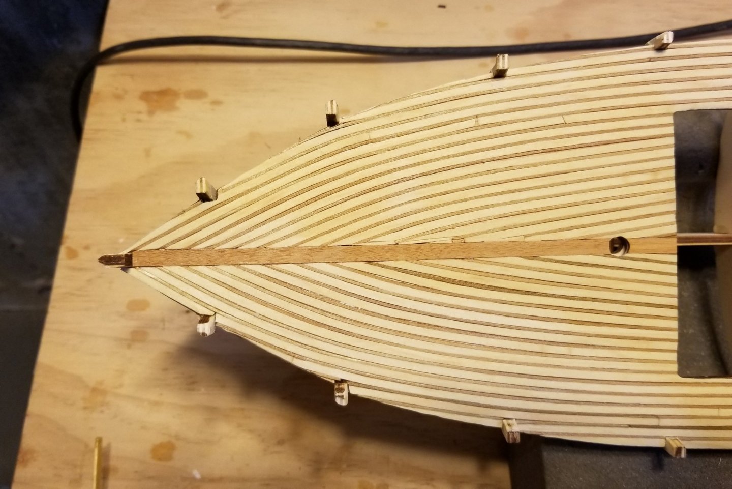
Deck planking now finished.
For those of you following the "alignment" saga on port & starboard sides, I have some close ups. At the bow, I was only able to maintain it (barely) by using stealers, and you can see them in the close-up.
At the stern, it's aligned at the very stern -- but that will be covered. Moving toward midships, the alignment falls off and I couldn't maintain it.
The issue is the angle at which the basswood planks hit the centerline. That angle determines the width of the butted edge, and if the angle coming in on the second side you plank is slightly different (which is almost inevitable, I think), you can't maintain alignment.
Ah well, I'm happy with the end result.
Regards,
David
- GrandpaPhil, yvesvidal, JayCub and 2 others
-
5
-
Started the deck planking. Nice pattern of alternating wide basswood and narrow walnut, with curve following the line of the boat. Will look nice when sanded and finished. The rough spot at the stern will fortunately be covered.
Now the trick will be to get the other side lined up exactly with this one where it butts at the center line.
Regards,
David

- JayCub, rshousha, GrandpaPhil and 2 others
-
5
-
John -- For display.
Regards,
David
-
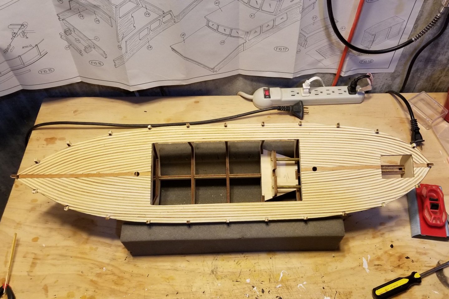
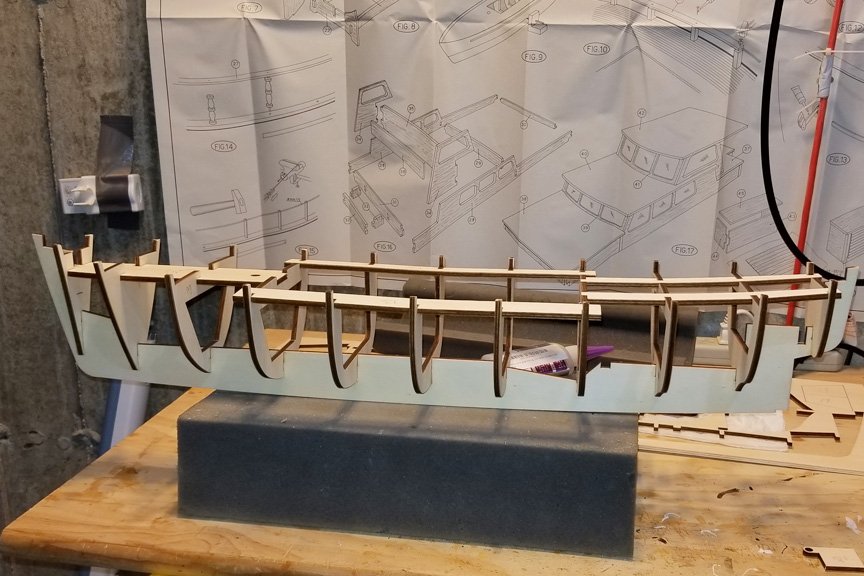
Here's the hull frame. Goes together nicely and a good fit all around. The frames and keel are plywood -- I prefer MDF (Amati uses it) as it's more rigid.
Regards,
David
- GrandpaPhil, yvesvidal, Tom E and 1 other
-
4
-
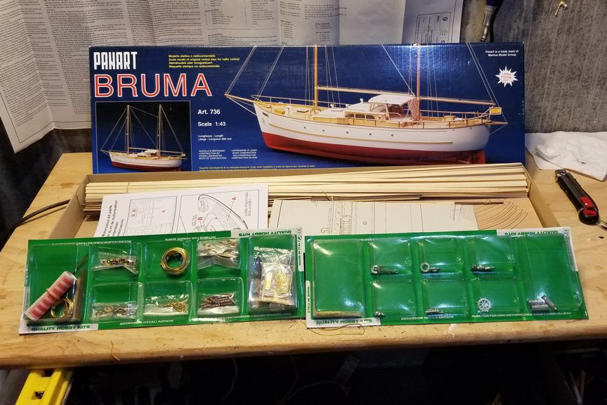
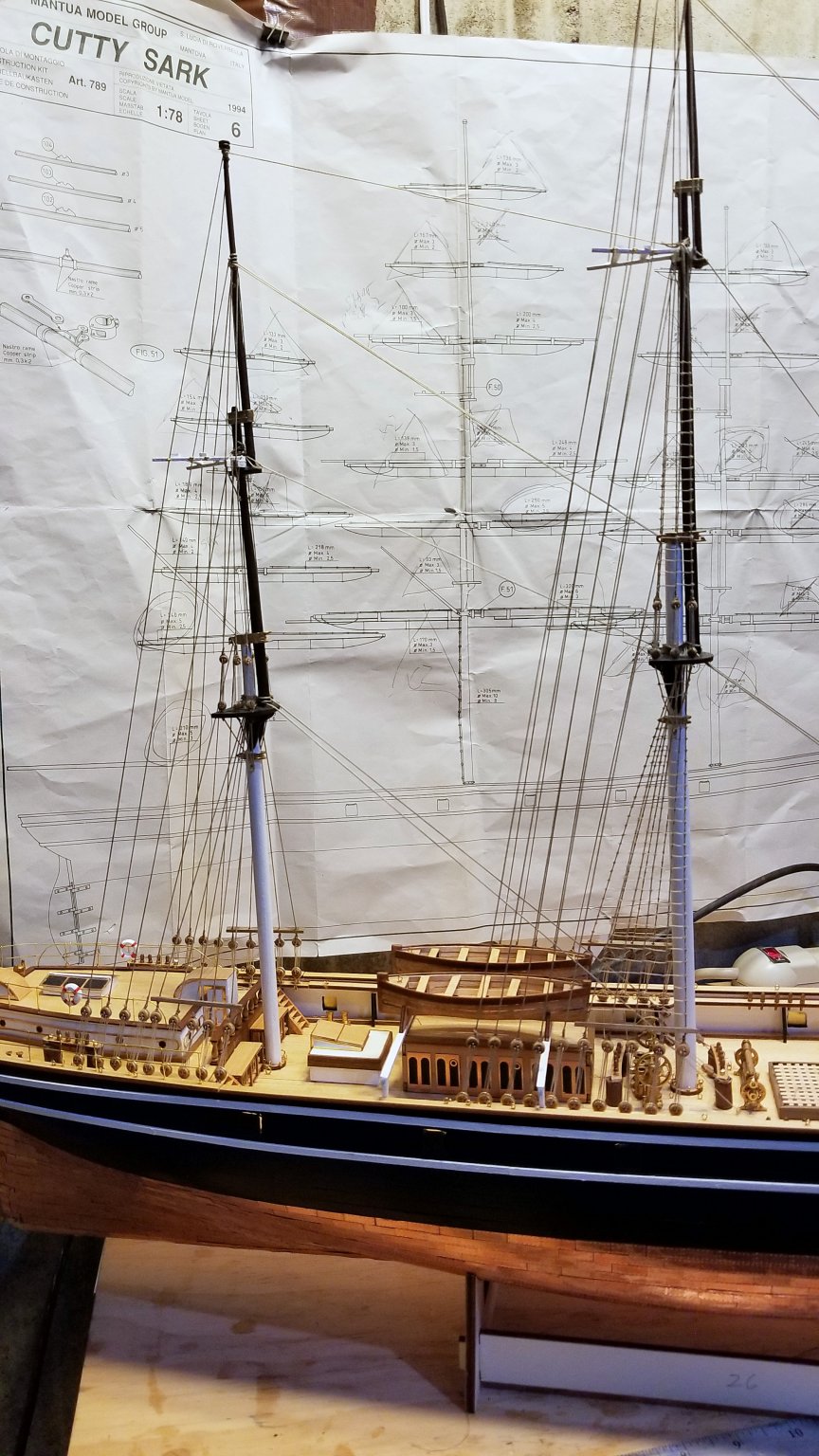
I'm starting the Bruma, which I chose to give me something hopefully less complex and long than the Cutty Sark.
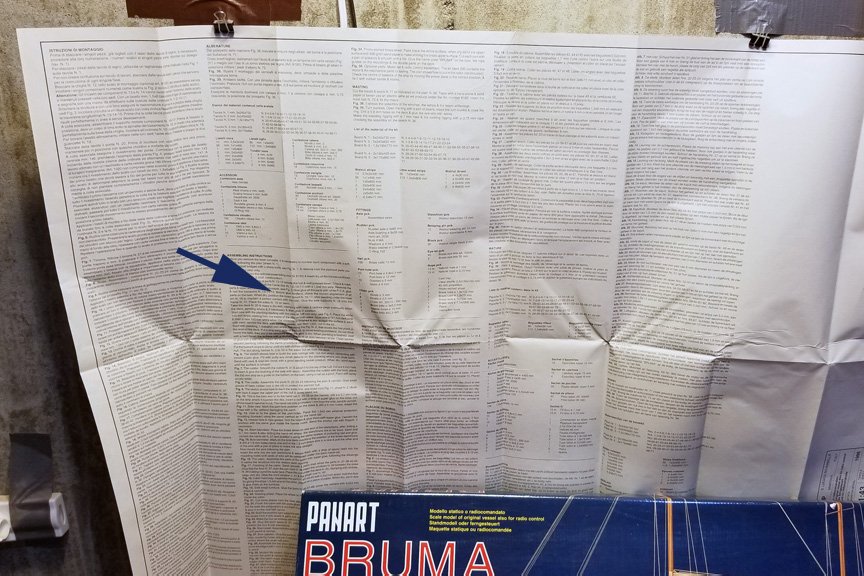
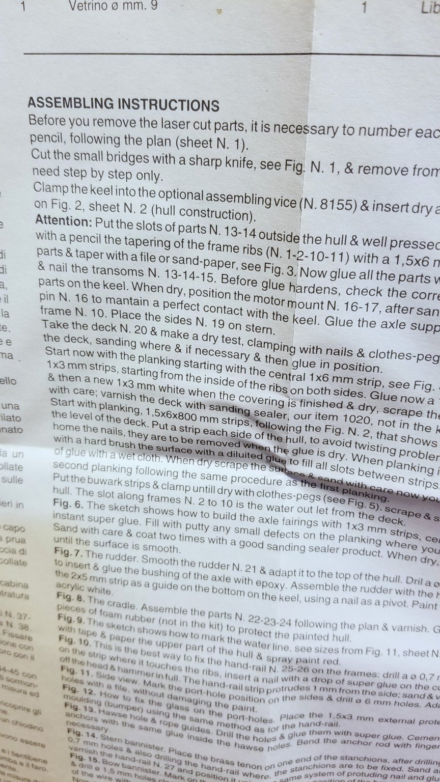
Here are some "What's In the Box" Pics. It's wood, laser cut sheets, some fittings, and plan sheets. The instructions are printed on the back of one of the plan sheets (in several languages). The English instructions are about one column length, including the parts list. What I'm going to do is scan them so I can print them out and still be able to use the other side of the plan sheet.
Regards,
David

- GrandpaPhil, ccoyle, yvesvidal and 1 other
-
4
-
-
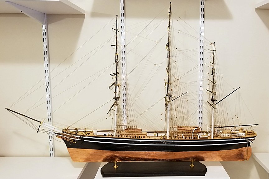
COMPLETED! A set of completion photos are in the gallery at https://modelshipworld.com/gallery/album/2021-cutty-sark-by-drobinson02199-mantuasergal-scale-178/
I enjoyed this -- my longest build at about 7 months. As I noted above, I'm generally happy with the kit, but would caution others about multiple parts shortages -- copper plates, certain blocks. I got around it with spares from my stash. I was also disappointed with the flag, which is printed on one side only. So I didn't use it. But other than that, it's a nice kit.
Regards,
David
-
Bender:
I've been happy with this kit, although it's not without its drawbacks. The wood and materials quality is fine. My major complaint is that there have been items where Mantua didn't supply enough in the kit -- more than one case. The biggest issue was copper plates, so be sure to get matching spares from whoever you get the kit from. I'd say 300-400 extra, which Ages of Sail sent me gratis. For other items (some blocks, chain) fortunately I have a leftovers stock from other builds that has backed me up. I would also say that the plan sheets are sometimes ambiguous and I had to study them carefully to figure out where something should go.
I haven't looked at other models or build logs of other Cutty Sark models so I don't have a basis of comparison. But I've built two Amati rigged ships (Revenge and Fly), and while the Amati quality is better, I have no complaints about this kit. It has a nice natural wood coloration at the deck level.
There is no sail plan included, but you can buy one from the National Maritime Museum (I bought the deck and rigging plans and didn't find them of much value to me). Here's a link to the sail plan https://shop.rmg.co.uk/collections/cutty-sark-gifts/products/cutty-sark-sail-plan-50-x-70cm
Interestingly, when I was in college (1960s) my roommate built the plastic model, and I thought it looked nice for a plastic one.
Regards,
David
-
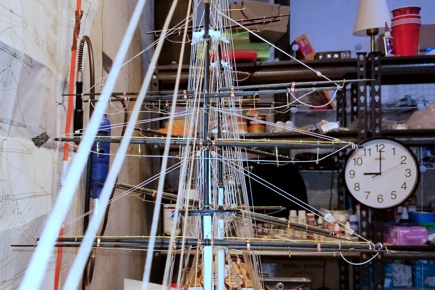
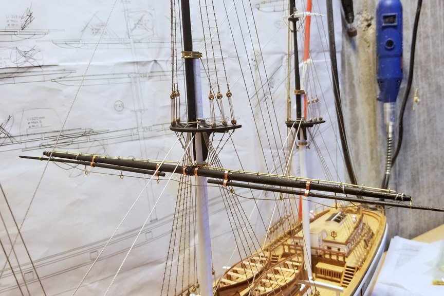
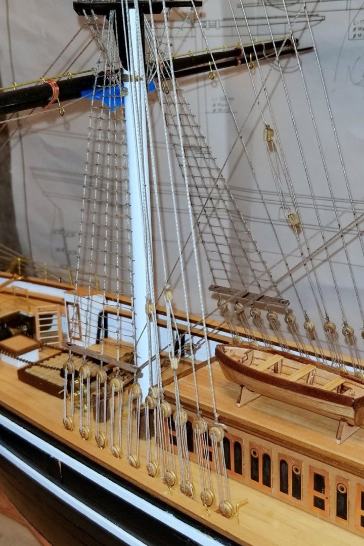
The yard lifts are all done now (see picture). The other picture shows the first piece of rigging on the foremast lower yard.
I'm now going to get into the yard braces, and I have looked at the rigging diagram and concluded that the best sequence for braces to preserve ease of access for rigging is:
- Do the top three yard braces on the main mast next.
- Then do all of the yard braces on the mizzen.
- Then the top two yard braces on the foremast.
- Then rig the inner brace on the main mast lower yard (matches the one I've done on the foremast lower shown below)
- Then rig the three lower yard braces on the foremast
- Finally, rig the three lower yard braces on the main mast.
If I do it that way, I hopefully will minimize contortionist activity getting "inside" rigging already installed.
Getting close to the end now.
Regards,
David

- petervisser, Papa, coxswain and 6 others
-
9
-
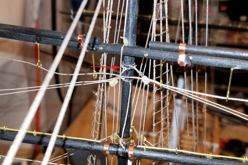
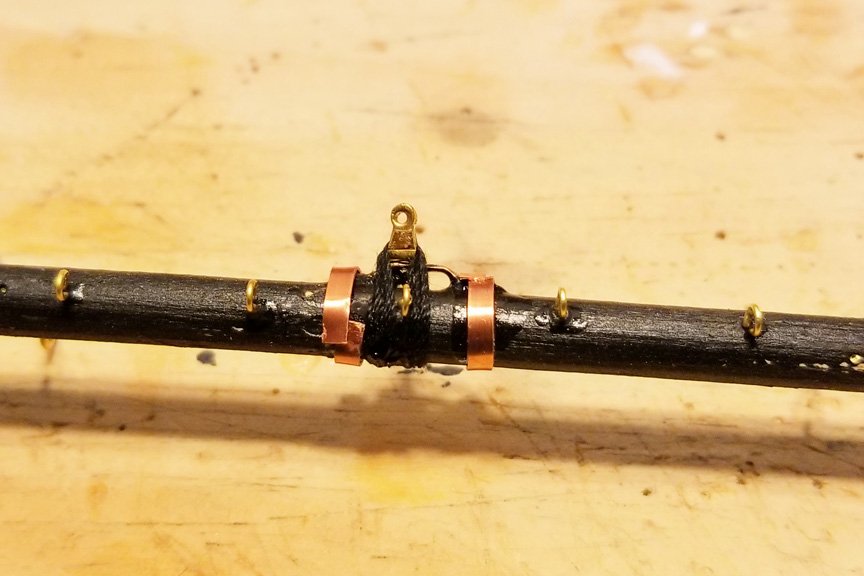
I'm in the process of rigging all of the yard lifts -- the ones that run from the mast to the tip of the yard (because all of the yards also have simple vertical lifts as well).
The bottom two yards are attached to the mast by a hinge, so they can take the upward force of the lifts. But the other yards slide up and down, so without doing something it wouldn't be possible to tension the yard lifts to get each yard to be horizontally lined up. Solution was to install a small vertical yard downpull starting with the third yard on the foremast.
Pictures attached show the first three foremast yards with the lifts rigged, and the small vertical downpull (marked with an arrow) that I used on the third yard up to create something for the yard lifts to pull against.
I'll be installing the lifts on all the yards on all the masts before turning to the other running rigging.
Regards,
David
- coxswain, vossy, GrandpaPhil and 2 others
-
5
-
Mike:
Your experience with Amati on parts is different from mine -- on all my Amati kits I have had a lot of leftovers in terms of wood, blocks, rope, etc. Now my Mantua Cutty Sark is a different story -- I have had to dip into my "stash" lots of times.
Regards,
David -
-
Mike:
I'm glad the log was helpful to you. I really enjoyed this kit -- and in fact have enjoyed everything I've built from Amati. The quality is really first class in their kits. On the Titanic box, it says "museum quality", and if you don't mess it up, that's what you get.
I have seen some members refer to the group of those who have built a Swan class ship (either Pegasus or Fly). Maybe we can be the start of the group that has built the Titanic.

-
And the finished product, hanging straight and true.
Regards,.
David
- gieb8688, GrandpaPhil, Javlin and 2 others
-
5
-
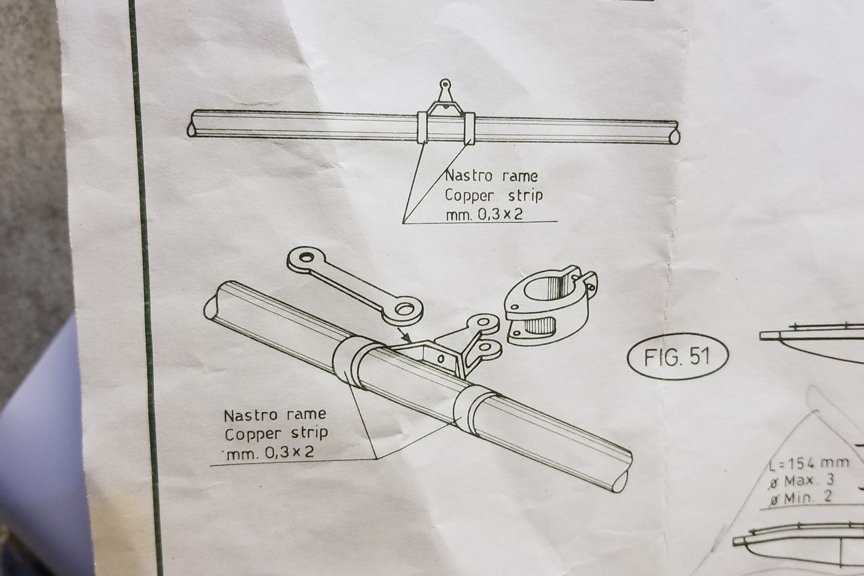
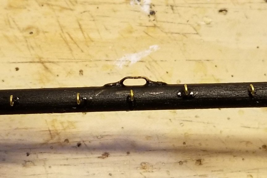
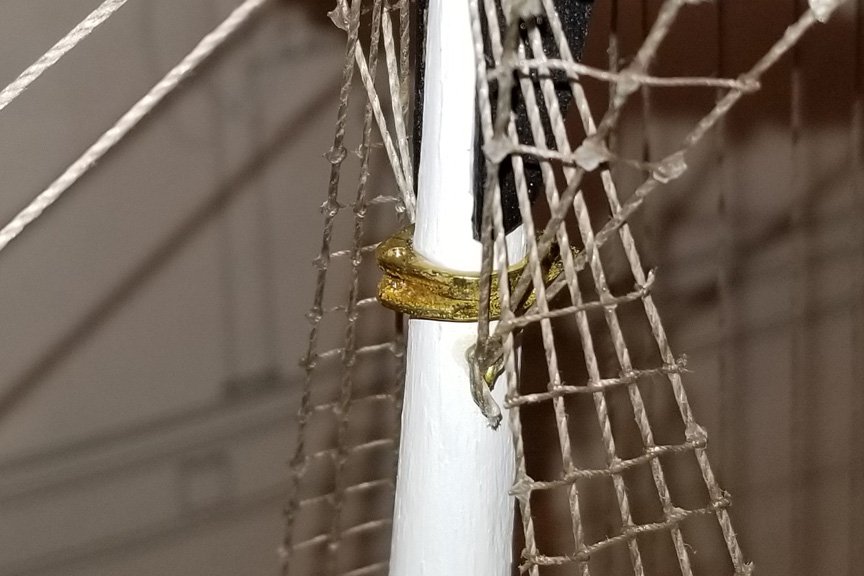
The two lower yards on each mast are mounted using a metal hinge and pin assembly. The picture of that from the plans is below. The components are shown in the next three pictures (assuming that the pics come out in order -- if the website reverses them, the plans are first and then it goes from there).
On the foremast, I had some real problems getting the "C" shaped fitting attached to the yard bracket. I didn't think a pin would help much and wasn't up for metal drilling, so I used CA glue. The issue there is that when you get the assembly up to the mast, if the horizontal alignment of the "C" fitting and the bracket isn't really good off (which is near impossible to do off the mast), you can get a situation where you can't get the yard to align horizontally -- which happened to me. It's also a very fragile assembly -- the CA doesn't hold well. My fix on the foremast was to lash the "C" fitting and the yard bracket together using black thread, and then fix it all with a drop of glue. I did that with the yard on the mast using the yard lift to help stabilize things while I lashed.
For the next yards on the main mast, I have done the lashing before mounting, and you can see that in the final picture. Now once I mount the yard, I can position it horizontally and then add a drop of glue around the lashing (being careful not to get any on the hinge).
Regards,
David

- gieb8688, Javlin and GrandpaPhil
-
3
-
-
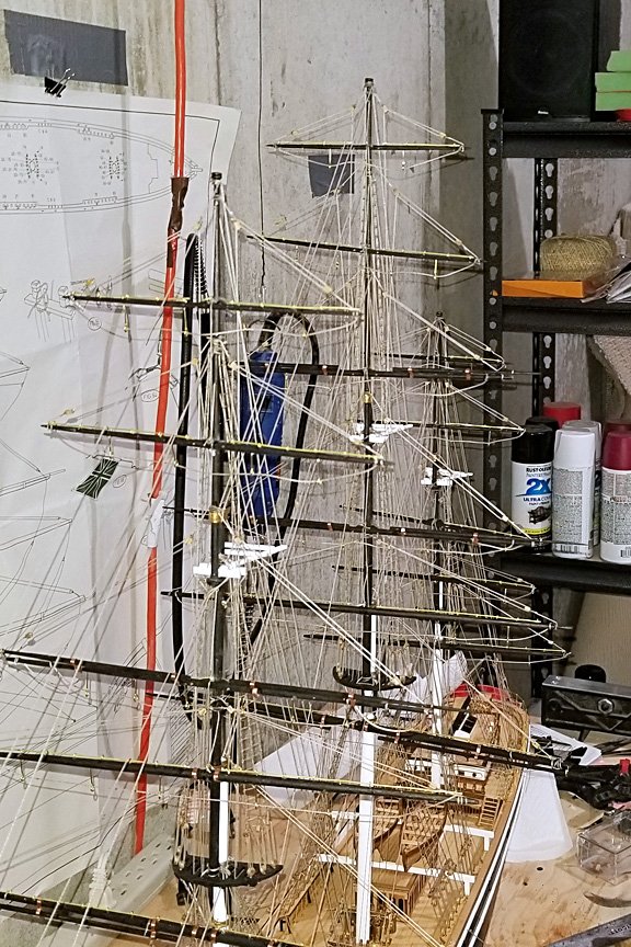
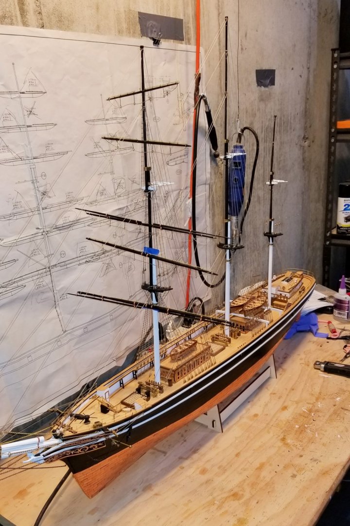
I now have the foremast yards up, which took a while because as noted above I wanted to stabilize the foremast with all of the stays before hanging the top three yards, which are only supported by the yard lifts, and I wanted to get their positioning right. So lots of standing rigging and ratlines. And I needed to do most of the main mast stays since it is partly stabilized by stays to the foremast.
The pictures below show the foremast yards, and you may see a bit of blue tape on the lower two where they meet the mast. They are mounted using a hinge assembly that has a lot of rotational play in it, so without the tape they would slant all the way over and partly turn. That of course will be fixed with the running rigging.
I'll now finish the main mast ratlines and then build the main mast yards and mount them, and then on to the mizzen. I'll have to do the mizzen stays before mounting the main mast yards -- again because some of those stays run to the main mast and will move it just slightly.
Regards,
David


Bruma by drobinson02199 - FINISHED - Mantua/Panart - Scale 1:43
in - Kit build logs for subjects built from 1901 - Present Day
Posted
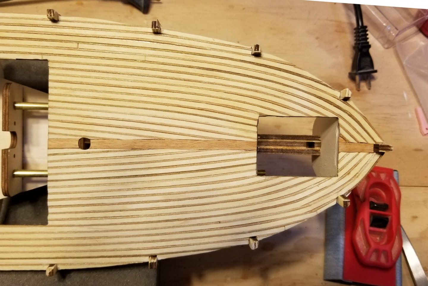
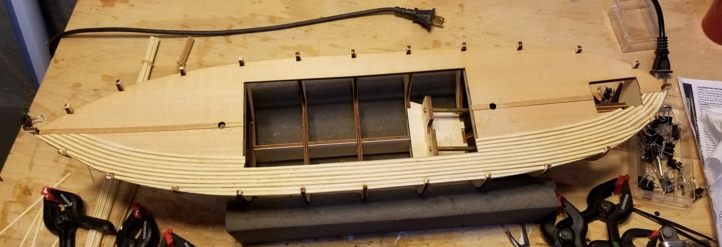
Working the first planking around the prop shafts. It's basically an improvizational act, and what I did was to create a "floor" of short planks on top of which I could mount the first planks under the shaft.
What you see in the finished picture will be dressed with a housing over the prop shaft to hide the rough area where it enters the hull. That goes on after the second planking.
I am about to go away for a couple of weeks, so won't fill and sand this until I get back.
Regards,
David