HOLIDAY DONATION DRIVE - SUPPORT MSW - DO YOUR PART TO KEEP THIS GREAT FORUM GOING! (Only 69 donations so far out of 49,000 members - Can we at least get 100? C'mon guys!)
×


BANYAN
-
Posts
5,946 -
Joined
-
Last visited
Content Type
Profiles
Forums
Gallery
Events
Everything posted by BANYAN
-
 Very nice joinery Danny; now for your next masterpiece I will expect to see a fully functioning chain pump.... cheers Pat
 -
Thanks Mark, Steve and Greg; I will stil try to find some larger beads if I can as I would like to retry these parrels in 'privet' also. The two bead shops we had locally have shut down unfortunately so off to farther pastures.... Don't worry about deleting the photos Steve, they help add to the story and I certainly don't mind. cheers Pat
- 517 replies
-
- 3
-

-
- Endeavour
- Artesania Latina
- (and 1 more)
-
Binnacles etc.
BANYAN replied to bluenose2's topic in Discussion for a Ship's Deck Furniture, Guns, boats and other Fittings
Bluenose 2 - I would try looking at the 1:72 plastic/resin kit upgrade kits etc from the like of White Ensign or L'Arsenal or Hannants etc. These suppliers produce PhotoEtch, resin, metal upgrade/up-detail kits/parts for many ship models in particular the steel-navy. You might even get lucky and find a set specific to the ship you are doing; but. more likely you may have to get a bit here, a bit there. I know for instance there are many parts for Flower class corvettes. A google search on say "1:72 ship model detail parts" will get you pointed in the right direction. It is then a matter of drilling down to find the scale/parts you need. More specific searchs on ship class or name may be more fruitful. cheers Pat -
Thanks Steve, that resolves the issue for me - now to source some larger beads Mark - I don't know whether to thank or curse you - Nah! Many thanks for the head's up mate. cheers Pat
- 517 replies
-
- 2
-
-
- Endeavour
- Artesania Latina
- (and 1 more)
-
Hi Chris and a belated welcome to the Endeavour Club - I have been quite remiss in missing your build. Your progress is good and the results look very promising - especially like the Kaurie deck planking. You have done well with the wales mate, I didn't even try to joint the wales back when I started. My build has progressively improved in detail accuracy, as when I started I was just learning how to; now, everything above the deck planks is scratch built. Kaurie is a great planking material, a couple of our club members use it extensively. Our Club President, whose model features in Karl Marquardt's book, built his model using the skeleton of the AL Kit (backbone and bulkheads) but then everything was scratch built using Kaurie only. I'll join the audience and follow your build from here on in. cheers Pat
-
Hi Keith, welcome back Some nice progress on the RW mate - I'd do the columns in acrylic also - adds that extra nice detail. cheers Pat
-
Thanks again all for looking in and the likes. Chris - no worries - just cost you a couple of 'frosties' Popeye - thanks mate - slowly getting there. Mark - now you have me thinking - Not sure to be honest - I thought the beads (wooden balls) just created a bearing type effect and were smaller - need to research now - John - now that would be a challenge - but, I need to try some of that privet you provided first. If the saw survives then maybe.... cheers Pat
- 517 replies
-
- 2
-
-
- Endeavour
- Artesania Latina
- (and 1 more)
-
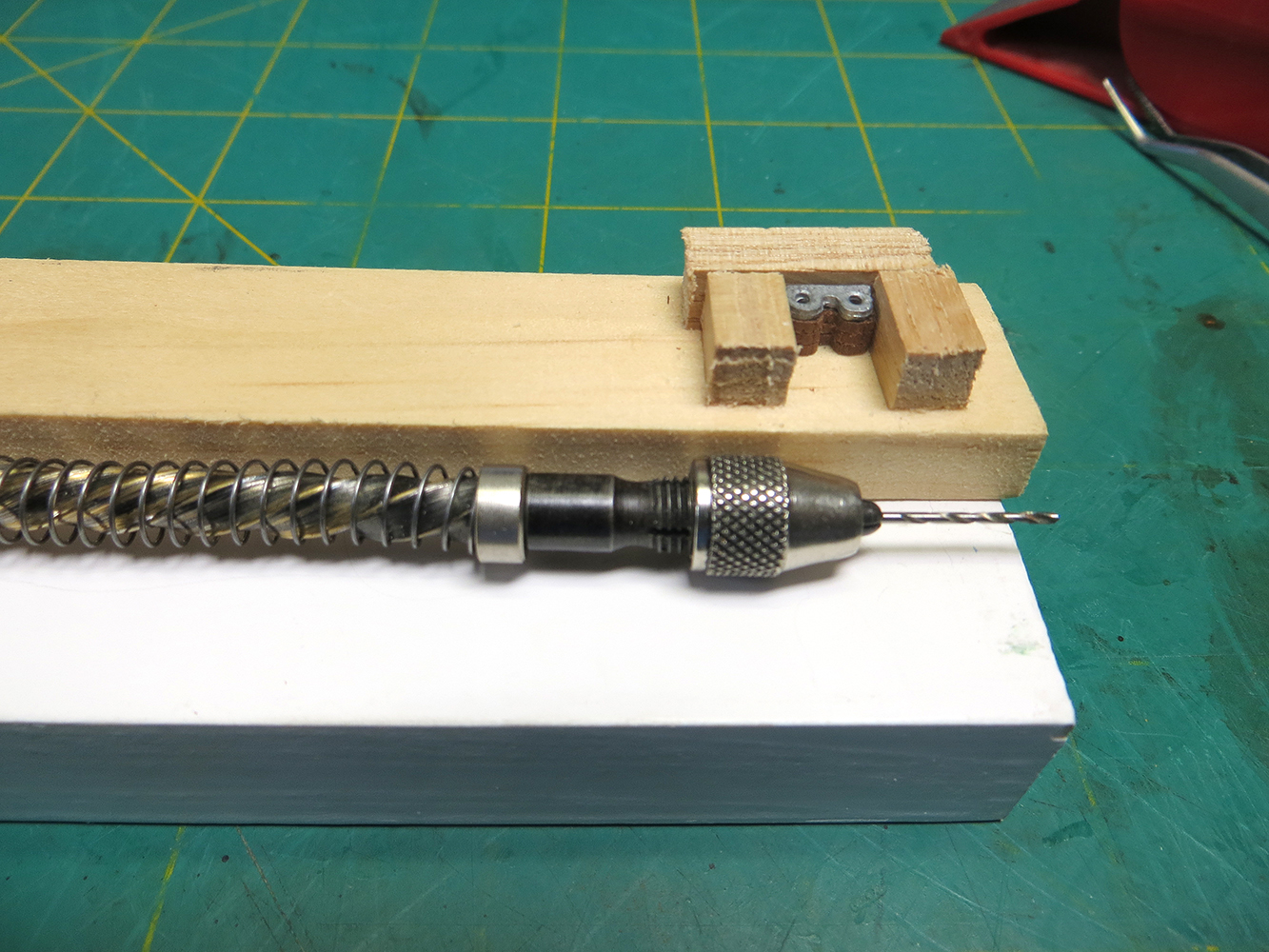
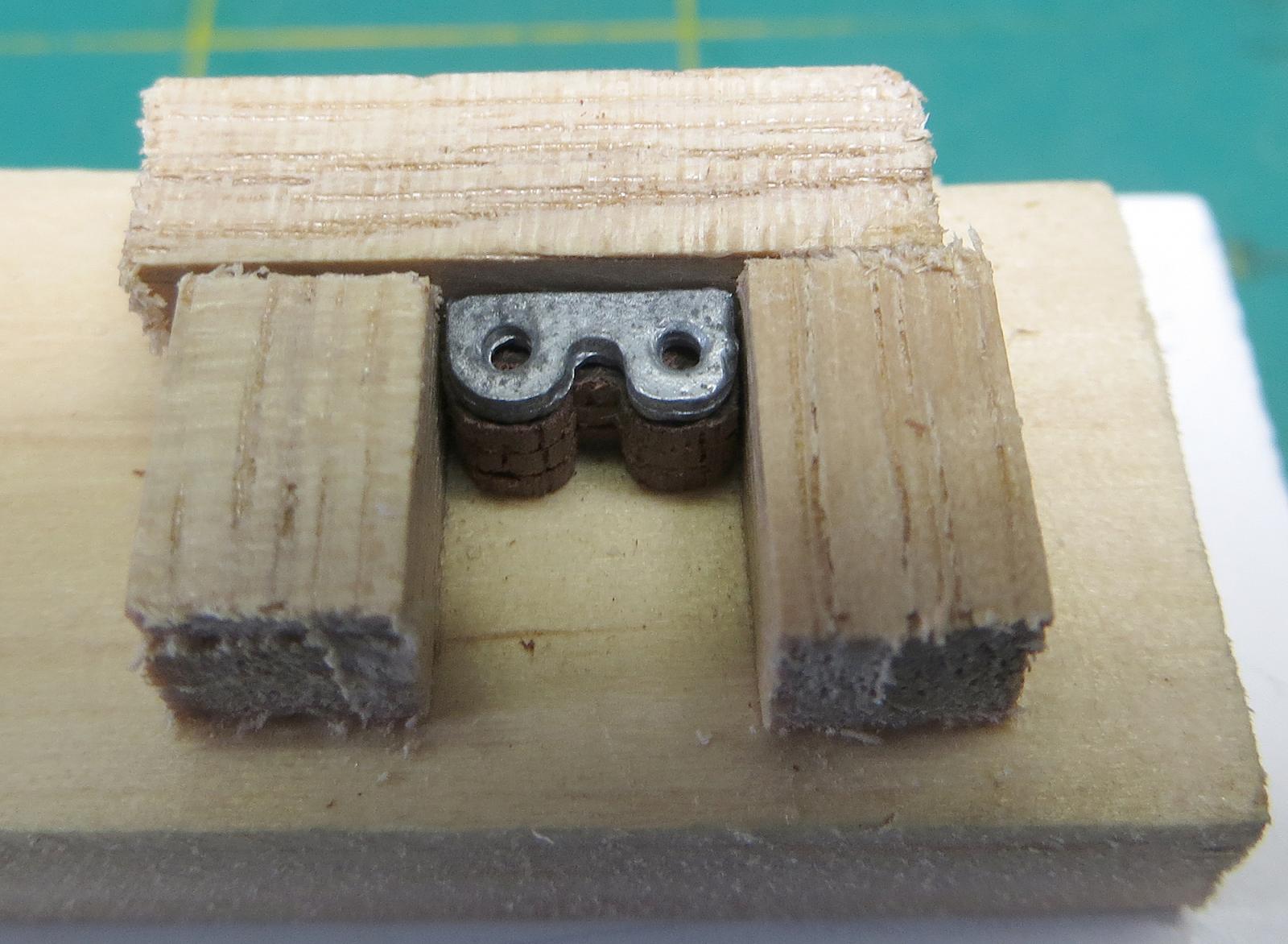
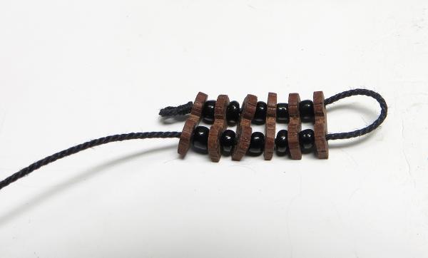
An update on the parrels - still experimenting so the following is not the actual completed product. For example, the beads I used are just as they happened to come out of the packet. Being cheap they are not graded to the same size and many are not evenly shaped etc. For the real deal I will sort/grade these to get a consistent spacing. The parrels are 0.75mm thick and the burning on the parrel pieces are caused by the saw blade - need a new one but will not ruin it cutting this hard wood. I have sanded off some of the char, but then realised these would have been 'greased/tarred' and would end up looking blackish anyway - saved some effort . I also found that stacking the parrels in the temp fixing jig caused the bottom ones to split and crumble when I was drilling so I have reverted to drilling and contouring the holes (for the bearings) individually; more time consuming but less breakages. Anyways - getting there. The parrels are actually quite smooth; the close up and contrast I have added make them look quite rough edged I am also going to try some privet (in the Boxwood family) to see if I get a better finish. cheers Pat


- 517 replies
-
- 9
-
-
- Endeavour
- Artesania Latina
- (and 1 more)
-
Hi Greg - looks great mate! Too late now I think, but the only option I could think of is to lay the red first then a single strip of masking tape of the appropriate width over it, then paint the other colours either side masking as required? Alternatively, you might consider auto pinstripe (red) and apply it like a decal then a coat of flat clear over it to seal it? cheers Pat
-
Great idea Cristi, this is thinking well outside of the proverbial box. Are the disks floating or do they have sufficient backing to keep them parallel across the whole platter when sanding? cheers Pat
-
WOW - thanks for all for looking in here and 'At a Glance' - much appreciate the interest and comments folks, they keep the mind positively focused.. yep John, that was for you Keith, very many thanks for your kind offer the other day. cheers Pat
- 517 replies
-
- 3
-
-
- Endeavour
- Artesania Latina
- (and 1 more)
-
Hi John, thanks for looking in. Hope all is well. cheers Pat
- 517 replies
-
- 3
-
-
- Endeavour
- Artesania Latina
- (and 1 more)
-
Hi Per, yep it is indigineous to Australia. Being so dense it is resistant to termites and very long lasting wood - they use it for railway sleepers, bridges and fencing due to these properties. Lately, some talented woodworkers have been making some great furniture from it also - but boy, tough on the tools take a look at this link - http://www.kropf.com.au/timber-furniture/river-red-gum.htm cheers Pat
- 517 replies
-
- 3
-
-
- Endeavour
- Artesania Latina
- (and 1 more)
-
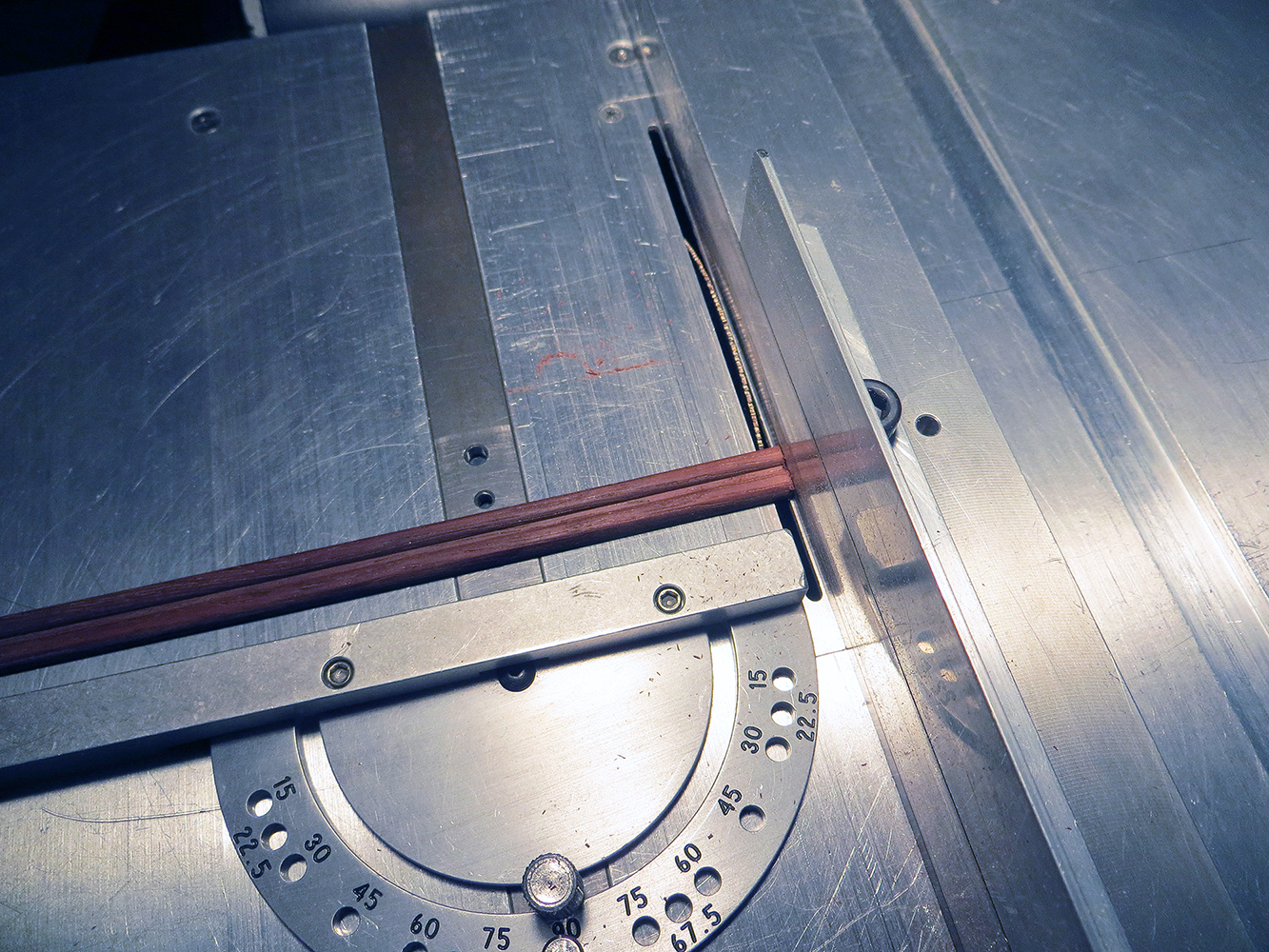
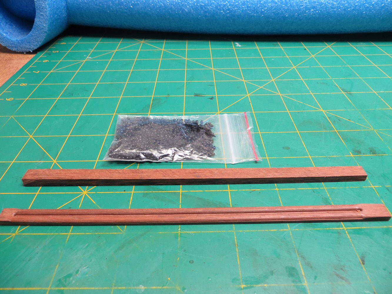
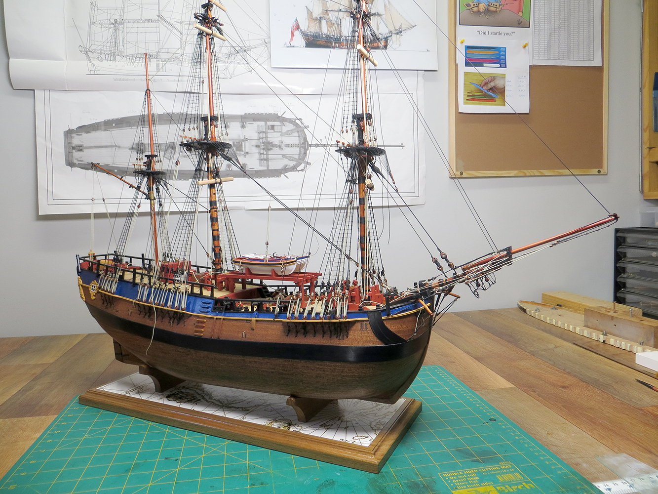
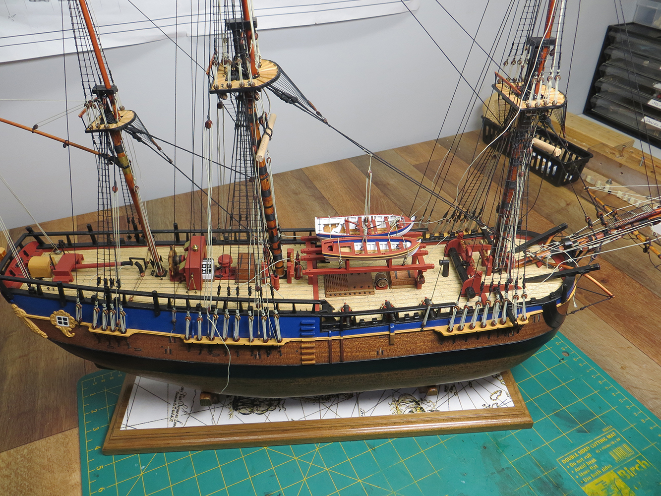
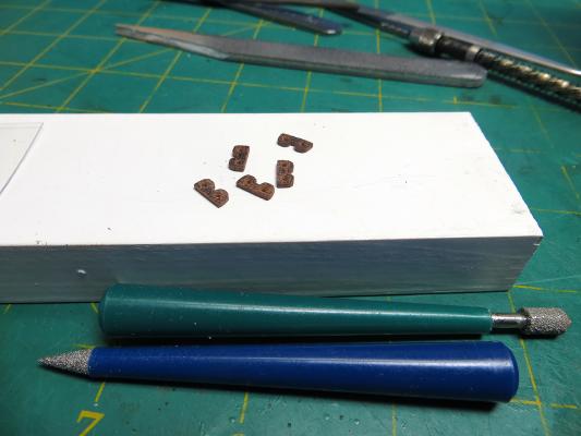
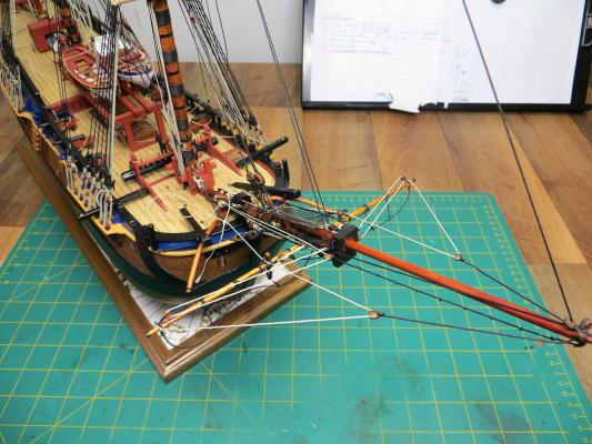
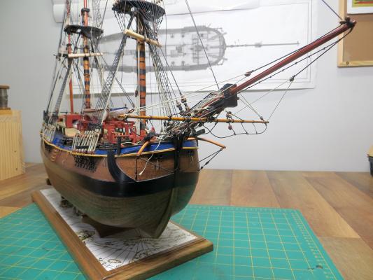
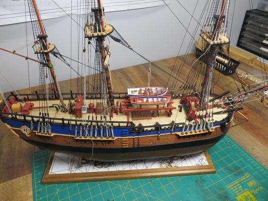
I made some further progress with the boom and jib but I have come to a temporary halt while I wait for some more beige line. I had purchased the running rigging thread prior to getting my ropewalk and cannot match the colour, so until my new supplies arrive in the next couple of weeks I have statred on making the parrels. The following photos show Endeavour at her current level of completion and in her display cradle. The top of the cradle is a copy of Cook's Chart for the East Coast of Australia that he drew while surveying his discovery of this part of our country - this has been sealed under a couple of layers of clear poly. There are still many lines/ropes that are only temporary secured waiting for final tensioning and the footropes still need to be stiffened into their final position. I am holding-off doing the final adjustments until I have stopped working in this area so that I don't knock them our or shape, or have to move a rope to fit another etc. The parrels have been made from Red Gum which is a very dense timber, so it will allow me to cut thin clices from the milled shape shown n the photo. I will drill the rope holes with indents for the parrels by hand using a template. The photo shows the stock after thicknessing, the milled shape and the beads I will be using. cheers Pat


- 517 replies
-
- 11
-
-
- Endeavour
- Artesania Latina
- (and 1 more)
-
Great news - a significant New Year milestone cheers Pat
- 786 replies
-
- 5
-
-
- Royal Louis
- Finished
- (and 1 more)
-
Thanks Steve
-
Hi again all. Thanks for the pointer to the painting jbshan. On closer inspection I think it does accord with Druxey's observations. I found a higher res of the painting at https://commons.wikimedia.org/wiki/File:John_Cleveley_the_Younger,_HMS_Resolution_and_Discovery_in_Tahiti.jpg The foot of the hoist appears to be in exactly the same sort of relative position to the rail as RMG painting? edit: oops - on review (zoomed) it appears this Ensignis larger in physical size BUT... it is being flown from from the gaff halyard and not the Ensign Staff. I think, for my purpose, that the proposed rule-of-thumb will suffice? cheers Pat
-
Thanks all, appreciate the feedback and pointers. I think the best estimate I can make is to follow Druxey's advice and base it on the visual evidence of conntemporarty paintings, drawings and models which equates to the 'hoist' being approx. 2/3rds the length of the staff. Once I have calculated this for my model (at 1:60) I'll see if Model flags has an existing size (they do 10 sizes of the Red Ensign for this period, so I should get something fairly close (I hope) Once of have established this size I will order a jack that equates to the same size as that used in the selected ensign. Thanks again all. Pat
-
Thanks for the rule of thumb Druxey; appreciated. Thanks Mark, a handy site. Once I work out the approximate scale size using Druxey's guidance I will order something close to the size. cheers Pat
-
Hi folks, I am starting to research the appropriate flags to fly from my HM Bark Endeavour (c1770) depicted in harbour - so Ensign to be flown from ensign staff aft, andUnion Flag (Jack) from the jack staff fwd. From other discussions in this forum I have established the correct ensign to fly (as shown below): I am assuming the design of the Jack will be the same as depicted in the top left corner of the Ensign - that is, NO red diagonal cross? From the CRW Flags website and BR 20 (thanks for the links in your other postings Beef Wellington) I have been able to determine that the appropriate ratios for size (width : length) is: 1:2 for the Ensign, and 3:5 for the Jack What I am trying to establish however is whether there is a standard/rule for the actual size of the flags (per ship rate/size) etc? What would be the actual size for the Endeavour to fly? Any help will be most welcomed. cheers Pat
-
Agreewith Greg; I think that is why Marquardt shows hooks and tackle for these stays rather than fixed rigging as in other publications - so they can be removed. cheers Pat
-
Steve, could you post a piccy of those cutters please. I have a pair of electronics flush faced cutters, but they mangle the thread at the edge of the cut - perhaps the brand (quality) may be crucial? Neat solution to the eye; I'll try that. cheers Pat
-
That is one heck of a "work of art" delivered by a very talented artisan Remco - a wonderful legacy you leave us mere mortals to follow cheers Pat
- 1,215 replies
-
- 3
-
-
- sloop
- kingfisher
- (and 1 more)
-
More than a little impressed Steve; that is a major undertaking repeating that level of detail over 12 shroud sets! I tried at scale 1:60 but just too fiddly for my 'fat' fingers and had enough issues with clove/restrictor hitch terminations. cheers Pat