BANYAN
-
Posts
5,533 -
Joined
-
Last visited
Content Type
Profiles
Forums
Gallery
Events
Everything posted by BANYAN
-
 Rob, some of those shots really show the very fine job you are doing with this model, very nice work indeed. I also very much enjoy reading the background discussion all of you are having in resolving the best possible outcome for her true lines and equipment placement. I just wish I had someone else with similar deep knowledge of the Victoria to bounce my ideas off cheers Pat
- 3,515 replies
-
- 2
-

-
- clipper
- hull model
- (and 2 more)
-
That rigging looks good Keith, I think you have done a pretty decent job of it. We are always our own worst critics cheers Pat
-
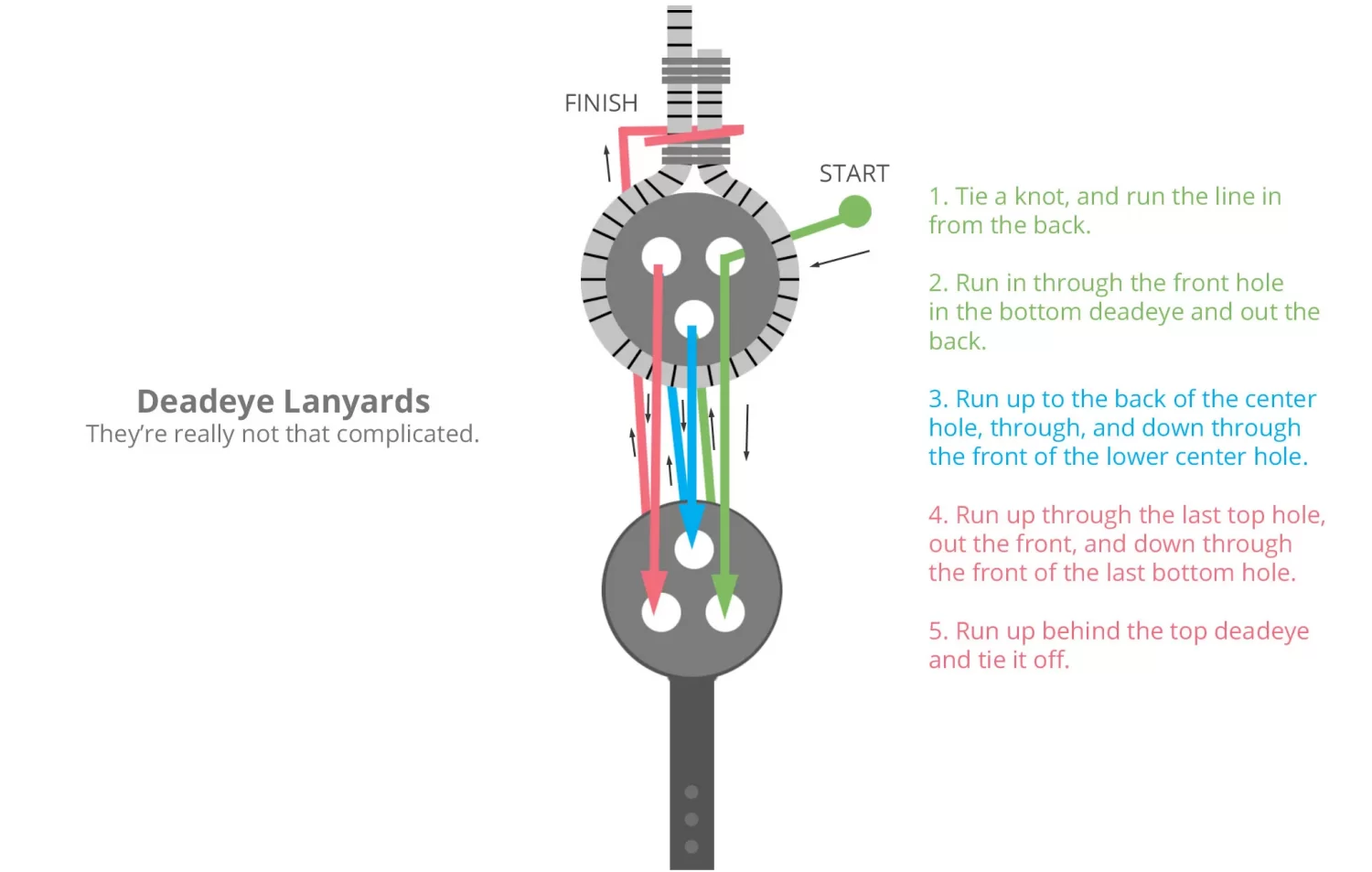
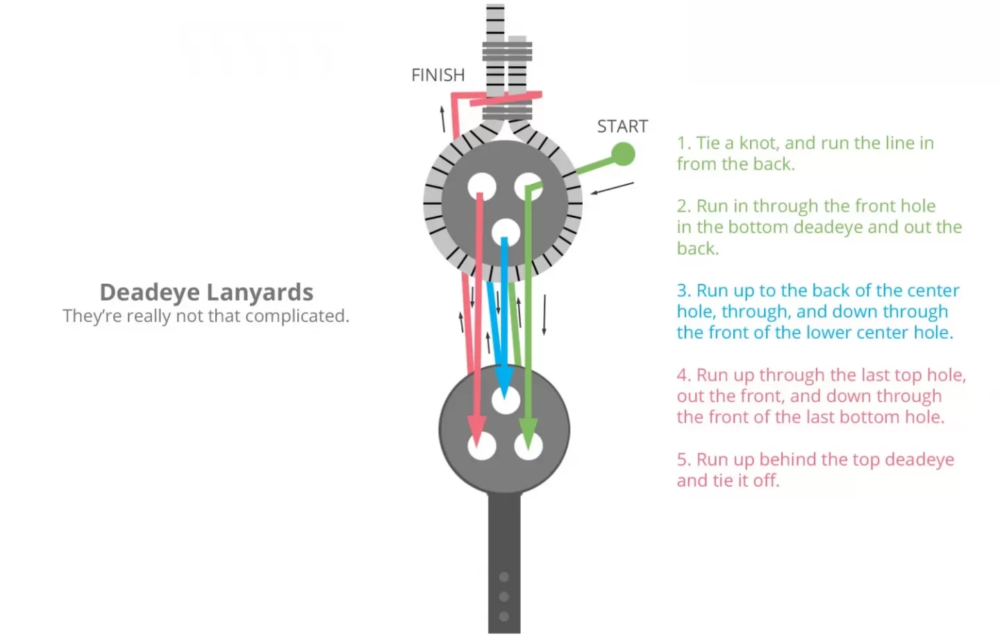
Hi Peter, that looks pretty good. Please note the lay of the rope for the shrouds may also affect the amount of twist. Most shrouds of this era were cable laid (left hand). I was referring to the sequence or method you actually put the lanyards through the deadeyes; from your response I am still not sure you understood my comment. Please ignore/forgive any unintended 'motherhood' in the following if you did understand. A good example can be found here in the forums at post #20 in the following link: Basically from forward to aft and not crossing (I note yours do not cross so may not be the cause, so it may be twist imparted from the shrouds themselves). Another helpful diagram is provided on the Suburban Ship Modeller website. Hope these clarify, cheers. Pat
- 79 replies
-
- 4
-
-
- Endeavour
- Artesania Latina
- (and 1 more)
-
You're making some significant progress Peter. The twisting of the deadeyes may be related to the way you reave them - have you done them the recommended way (as in the real ships)? cheers Pat
-
Oh how I know about those chores - they seem never ending cheers pat
-
Ditto the above - mate you will just have to stop work, I am running out of superlatives for your workmanship and detail. cheers Pat
-
HMCSS Victoria 1855 by Banyan - 1:72
BANYAN replied to BANYAN's topic in - Build logs for subjects built 1851 - 1900
Thanks for looking in and the info Steven; appreciated. Yep, the one and the same vessel. In her early years Victoria was attached to the Water Police with her Captain dual ranked as a Commander (Victorian Navy) and as a Police Superintendent, the rest of the crew were similarly dual rated based on their ranks. I was aware of the Shenandoah and the antics surrounding her visit. There is an excellent display and artefacts held by 'SeaWorks' in Williamstown, (some in the the "Pirates Bar'), if you are ever down give me a hoy and we could go visit. Also of interest, Churchill Island (near Phillip Island in Westernport Bay) has a couple of cannon on display in the grounds which they proport are from the Shenandoah. Attached is a piccy of the model of (Capt. Douglas) Elders Gun Raft 'The Elder' for anyone interested. cheers Pat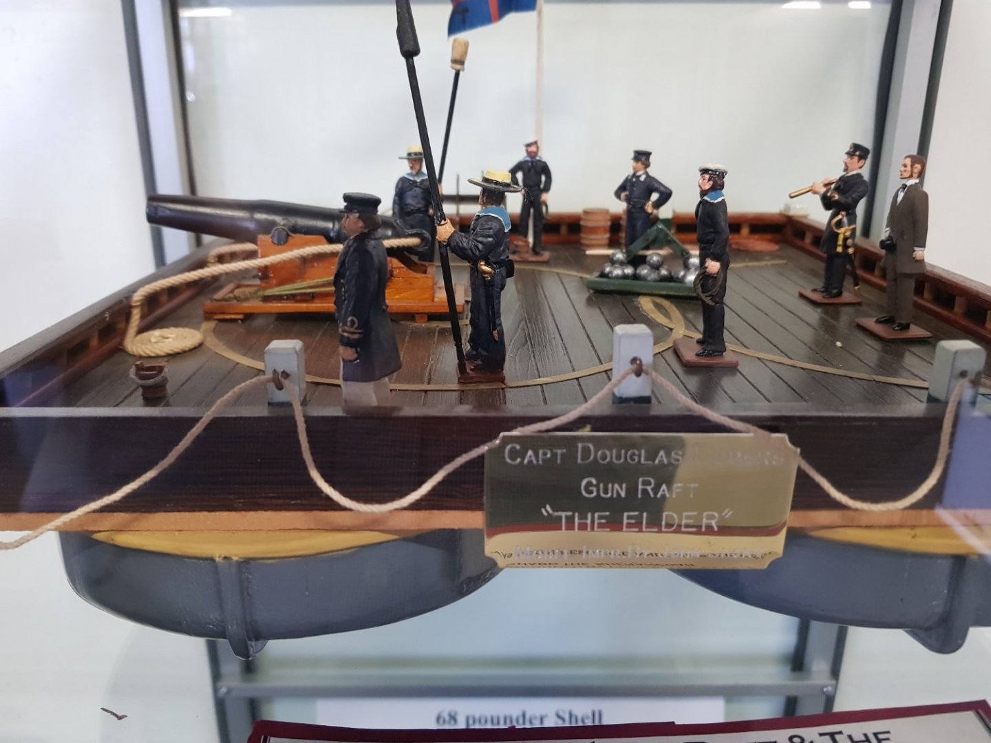
- 973 replies
-
- 12
-
-
- screw
- gun dispatch vessel
- (and 5 more)
-
Very clever indeed. The yards with their furled sails look very effective, I will really have to try your technique. cheers Pat
- 3,515 replies
-
- 2
-
-
- clipper
- hull model
- (and 2 more)
-
Ouch, hopefully not a difficult repair? The 'canning' effect looks good Greg. cheers Pat
-
All I can say Keith is WOW! but even that did not sound right beccause my lower jaw is still dragging on the ground. cheers Pat
-
HMCSS Victoria 1855 by Banyan - 1:72
BANYAN replied to BANYAN's topic in - Build logs for subjects built 1851 - 1900
Thanks for all the comments, likes and support/encouragement folks, much appreciated. Some good ideas presented/offered which may cause me to revisit my technique. The use of the crossed pieces inserted into slots sounds promising, thanks Eberhard. cheers Pat- 973 replies
-
- 5
-
-
- screw
- gun dispatch vessel
- (and 5 more)
-
Woolwich Royal Dockyard archaeological investigations
BANYAN replied to bruce d's topic in Nautical/Naval History
Nice find Bruce, makes interesting reading. cheers Pat -
HMCSS Victoria 1855 by Banyan - 1:72
BANYAN replied to BANYAN's topic in - Build logs for subjects built 1851 - 1900
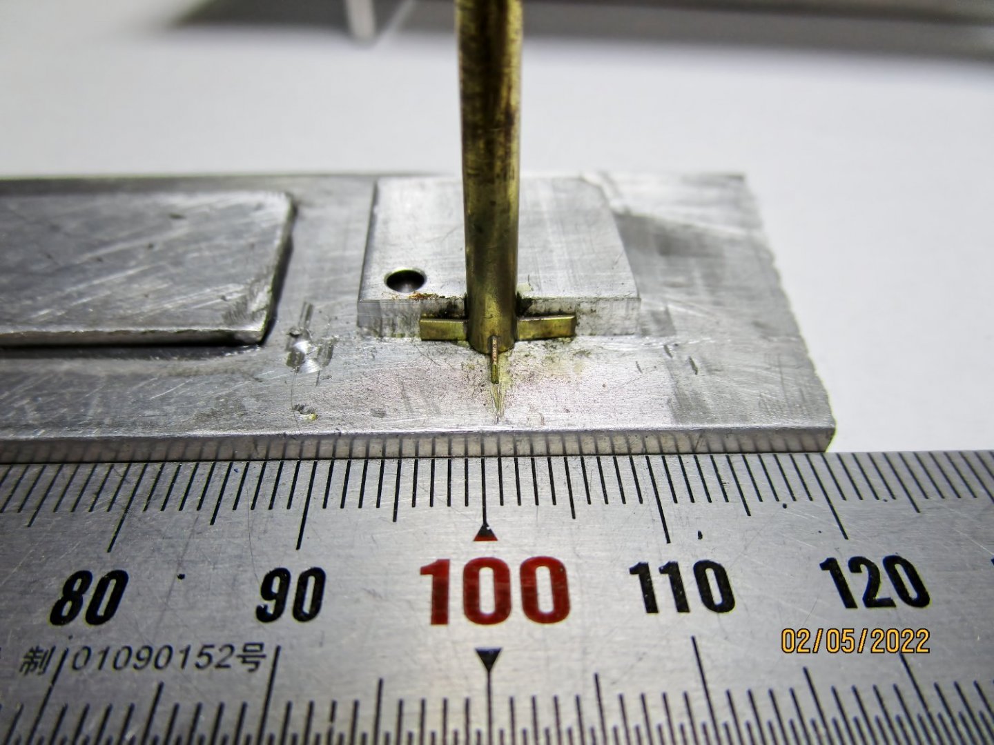
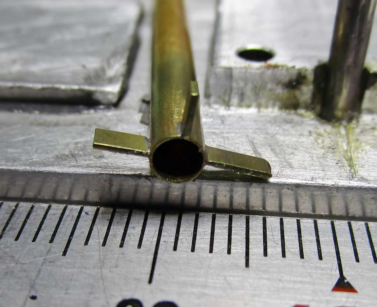
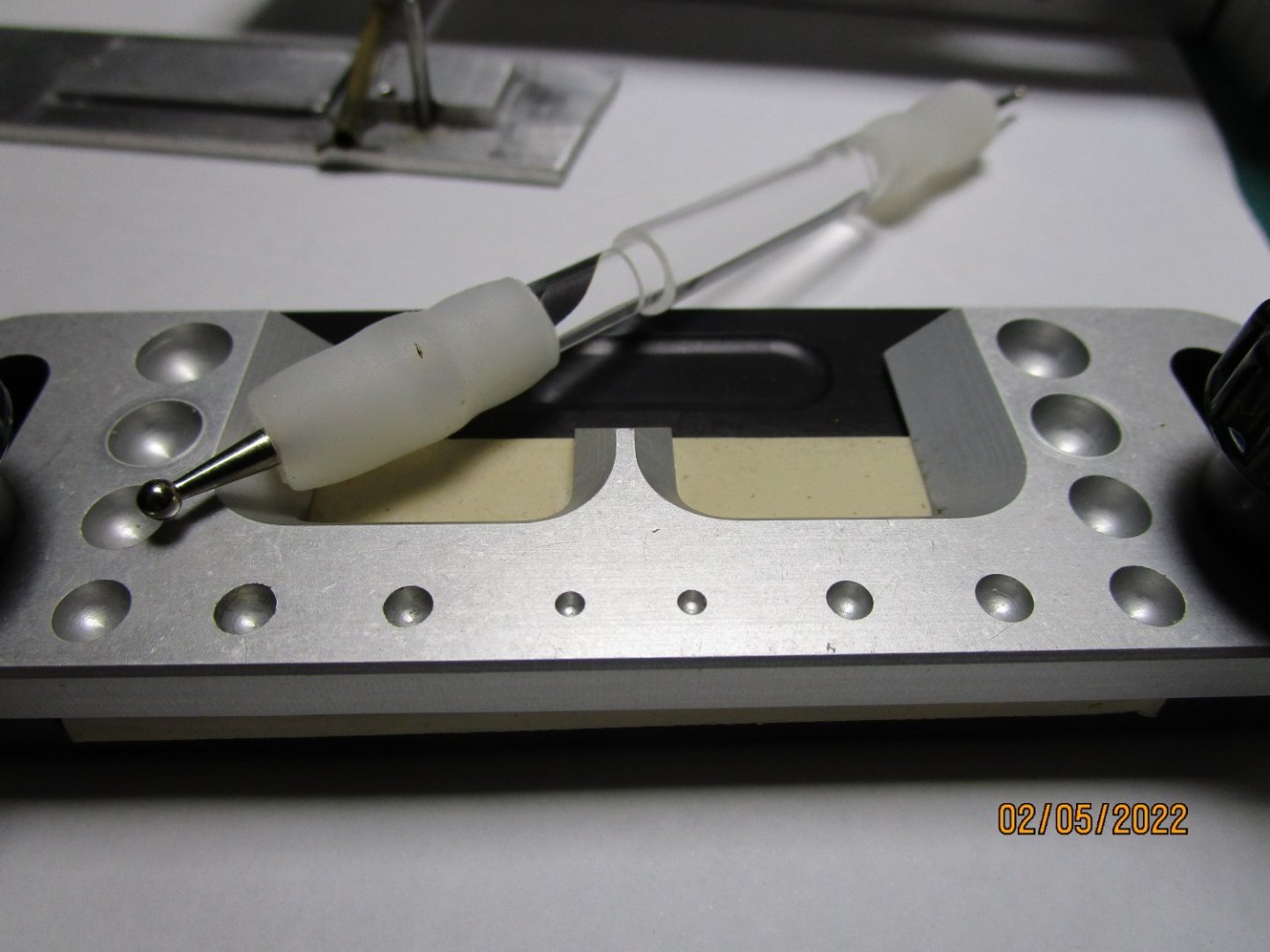
Next up are the spiderbands which require lugs to be soldered to some small thin walled tubing. I made up a jig which I think is self explanatory. I used aluminium as the solder will not stick. The jig allows me to keep the lugs square to the tube even though in the photo they don't look it (optical illusion). These lugs have yet to be drilled, shaped and cleaned up, then I will use a razor saw to part of 1.5mm wide band with the lugs attached. The real tricky part will come when I have to try and impart a very shallow taper to the ID of the tube; hopefully the solder (silver soldered) will hold. cheers Pat


- 973 replies
-
- 13
-
-
- screw
- gun dispatch vessel
- (and 5 more)
-
HMCSS Victoria 1855 by Banyan - 1:72
BANYAN replied to BANYAN's topic in - Build logs for subjects built 1851 - 1900
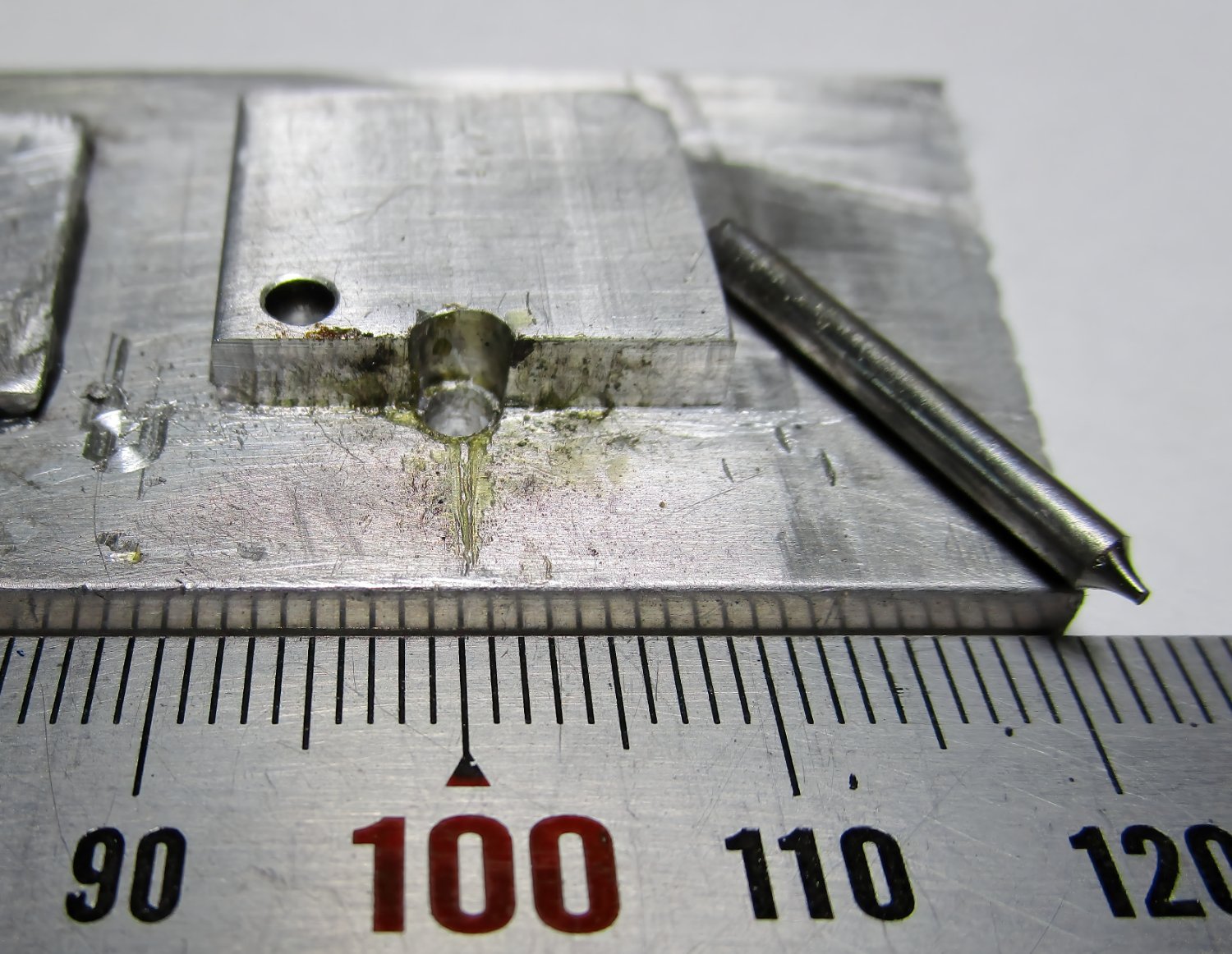
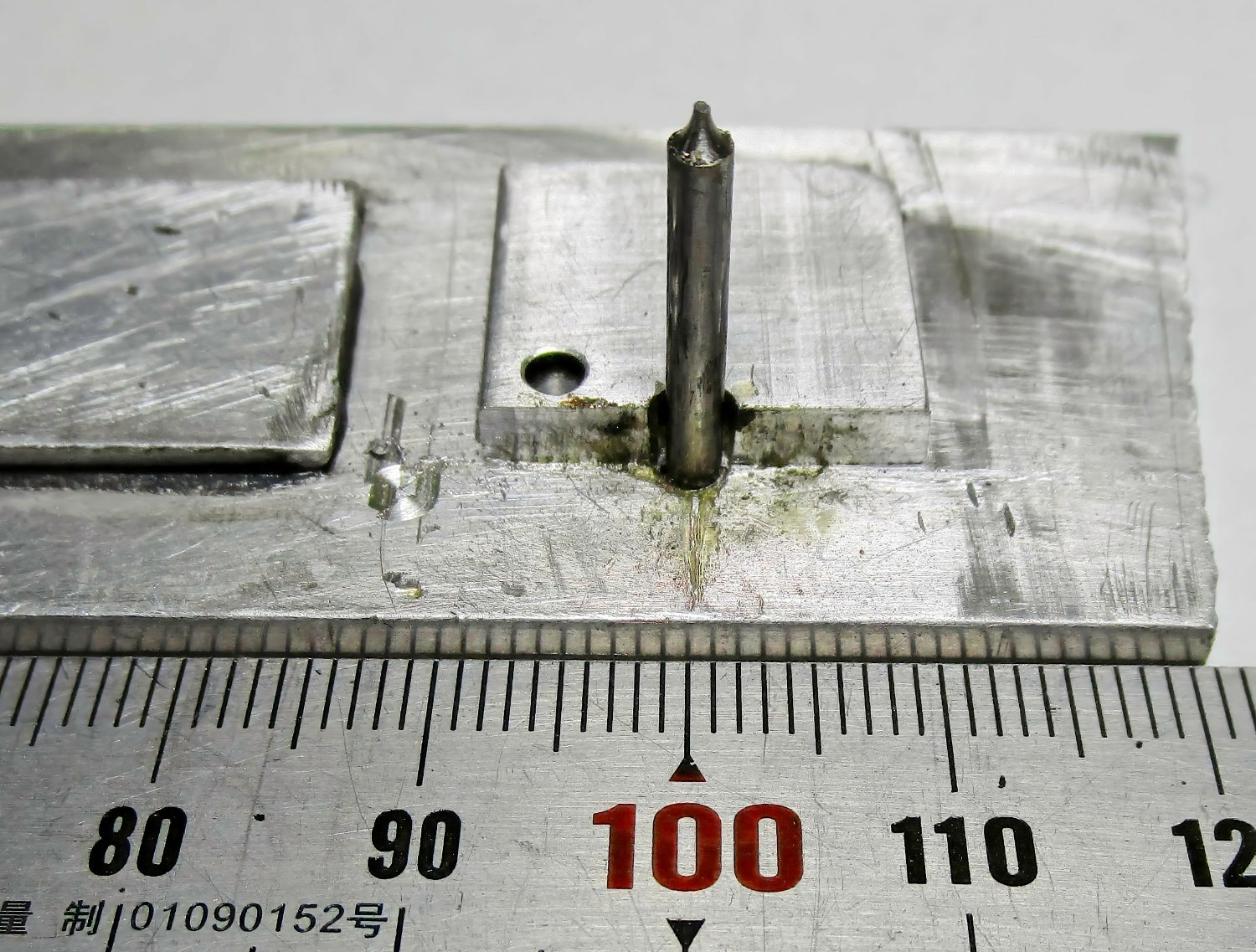
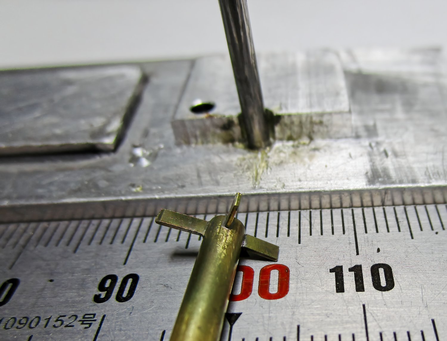
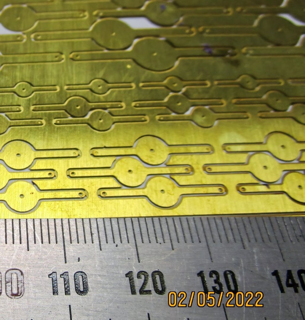
Well, I have finally got myself back into the workshop and started on some of the smaller fittings to be used in rigging the ship. The first are the fittings for the lower studdingsail/swing booms for which I need to make the ferule with gooseneck, and the spider bands. Noting the boom diameter is only a few millimetres in diameter, these are quite small. For the ferule I decided PE was the way to go, so drew up the basic stock parts. After experimenting I found I could not consistently 'round' a non-circular piece to form the concave end, so ended up going with a circular bit. I formed the concave shape by using a PE bending jig I have that has dimples inset for this purpose, then pressing the shape using a burnishing tool. I could not use tube for the bands as the diameters differ so I soldered a thin strip. The following are a couple of photos showing the end result of my first attempt where the alignment leaves a bit to desire, but overall, when viewed at eye distance, they look OK - not so great close up s they have not been cleaned up yet (the ruler is in mm). I will use some wire inserted in the end (through the preformed hole) as the start of the gooseneck. cheers Pat
- 973 replies
-
- 10
-
-
- screw
- gun dispatch vessel
- (and 5 more)
-
What a beauty! Very nicely presented and a well constructed Model John. You should be proud of this one. cheers Pat
-
Simply wonderful work Eberhard; she/he is turning into a very eye-pleasing model. cheers Pat
-
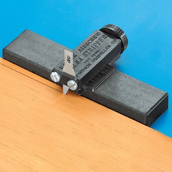
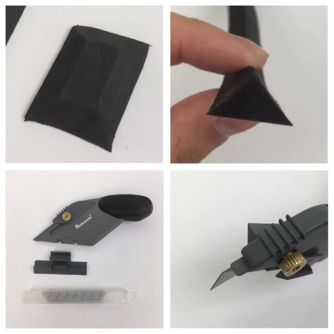
Allan, there are sure to be better solutions offered by the more experienced/talented builder but I used a 'splitter' tool generally employed by RC aircraft builders. I cut some very tight grained wood in thin strips to the required thickness to form the 'molded' dimension, then use this tool to take off thin strip to form the width of the stile etc. Below is a picture of the tool which I use with a jig clamped to a solid and straight edged cutting surface. I form a fence on the edge of the jig or table to guide the tool having clamped the strip to the surface (ensure it is square to cutting direction), and such that the cut strip between the tool and the stock ( I find that minimises the splitting sometimes experienced - a sharp blade is essential . Apart from the splitting, the other reason I have the cut piece restrained by the tool, is to stop it 'curling'. I hope that all makes some sense? There are various types out there, the first below is the style I used but I have also seriously thought of trying those card style cutters available from Office Supplies. The second image is a foam cutter that may also work? cheers Pat

-
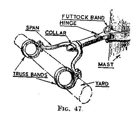
I think perhaps Barbara may be referring to the 'iron truss' that replaced parrels for the lower yards? Can you confirm please Barbara? See below which is an illustration by Harold Underhill in his Masting and Rigging Clippers and the Ocean Transport - Fig. 47. If so, there are some useful photos and illustrations available, but I have yet to find any useful guidance on the dimensions, especially the gap formed by the 'U' part - this gap allowed the upper masts to be struck through the resulting hole created when fitted to the yard. Some had a single joint/knuckle (hinge), others were double jointed to allow better clearance of the yard. when swung. As illustrated, they were usually incorporated as part of the lower futtock band. I do not know what type the 'Morgan' may have been fitted with? cheers Pat
-
NAIAD 1797 by Bitao - 1:60
BANYAN replied to Bitao's topic in - Build logs for subjects built 1751 - 1800
Very much up to your very high workmanship; a delight for the eyes. cheers Pat -
I think you may have started a new method for doing furled sails They look great, even up close. cheers Pat
-
I know that feeling only too well Keith. Very nice details to your launch, I particularly like that little engine/power derive. cheers Pat
-
Very nice work Brian; as Keith says, if you call this 'little progress' well .... Impressive detail. cheers Pat
-
John, many thanks for the explanation; I have learned something very interesting today. Appreciated. cheers Pat
-
hi John, ditto comments above - congrats to the team; the project is coming along very nicely and the additional detail in the photos is great to see. You have me somewhat confused though with the naming of the aux boiler. I am more familiar with that being the 'Donkey' boiler; not saying 'Doctor' is wrong, just wondering how you arrived at that name? Enquiring minds and all cheers Pat