


Snug Harbor Johnny
-
Posts
1,439 -
Joined
-
Last visited
Content Type
Profiles
Forums
Gallery
Events
Everything posted by Snug Harbor Johnny
-
 Good point, as I hadn't noticed the deadeye until it was pointed out and I looked again closely ('Just ordered new glasses because my prescription changed, but it will take 1 - 2 weeks to get them). 'Guess Keith and I share a couple traits, since on a Pennsylvania long rifle I made (and was showing to some new friends recently) - I kept pointing all the things I 'did wrong' (mostly small details). A man with some expertise in antique firearms said to forget real or imagined 'faults' - he thought it was beautifully done ... as is Keith's U.S.S. Tennessee !
 -
Who says that the deadeyes have to be 'perfectly' aligned? As they are tensioning devices, variations are bound to occur over time as shrouds get periodically adjusted. Your ship looks just fine.
-
'Love the shellac - at 1:192, you're a brave man.
- 155 replies
-
- 1
-

-
- Red Jacket
- Marine Model Company
- (and 2 more)
-
I've shared your job of adding-to or subtracting-from bulkheads ... Edit: Some might say shared your 'pain', but it not really that (although inconvenient) - its part of the journey, and keeps the mind working. We're told that having mental tasks in old age can stave-off Alzheimers - so with the stuff I'm fiddling with, I might match my Dad's intact mental abilities before he 'passed over the bar' a month shy of his 95th birthday.
-
Frayed lines
Snug Harbor Johnny replied to Dindsy's topic in Building, Framing, Planking and plating a ships hull and deck
Bob offers much good advice. Once I learned how to use the Syren 'Rope Rocket', I became hooked on making my own line because I can control the color by the use of material, and the thickness by varying the number of strings used in the layup. 3 threads (one on each of the three hooks) make 0.010" line (1" rope at 1:100 scale), 6 threads (2 per hook) yields 0.020" line, and 9 threads (3 per hook) yields 0.030" - very convenient at 1:100 scale. More threads or using already laid rope on the hooks can accommodate larger scales. OR - you can by scale rope from sources mentioned in earlier feedback. You put so much time and effort in a project, so why not use better scale rope. The same goes for blocks. True, it adds some cost - but the results are worth it. My early rope batches used Mettler poly thread, but there was some 'fuzz' (not as much as 'kit rope'), and my flaming process used an old-fashioned alcohol lamp with 90% isopropyl alcohol (for the lowest heat level compared to other fuels) ... and a QUICK hand, for any slowness and the poly line would part. BUT, the thread to use is Gutermann - which has almost not fuzz - so no flaming was needed, and the scale rope suppliers use Gutermann. Also, a 350 degree treatment of the hanks on a cookie sheet for 5 -7 minutes 'sets' the rope, and (unless worked) does not ravel on its own. Scale rope suppliers have already tempered their line. Listen to Roger - don't let any flame get near your model ! I like using shellac for a variety of applications. If the rigging already in place were not waxed, slightly thinned (experimented first) amber shellac might have darkened the ratlines and deadeye laces, and lessened fuzz at the same time. -
I suppose that might have originated when wenches aboard would lean over the 'railing' to display their wares.
-
My Dad once made two smaller scale clippers (1:120 Scientific kits), and used flat toothpicks that were about 0.040" wide - representing about 4.8" planks. Perhaps a tad undersized (6" scaled planks might have been better), but they looked OK and did not need any 'dots' at the butt joints. The non-tapered portion of the toothpicks he used (cut off with a razor blade) measured about 1.6" long, representing 16 foot lengths at 1:120 . I've no idea whether this sort of tooth pick is available anymore. I've seen thin wooden coffee stirrers that would do for plank stock at a larger scale. Hmmmm, 'don't know what scale the doctor's wooden tongue depressors would be, widthwise. I have various sized of pre-scribed decking stock (still available and most often used for modeling wood-sided buildings in railroad layouts or dioramas) that I'll use as needed, rather than do it plank-by-plank. That seems the easiest way to get 'good enough' results. Its like the Coach in "Cool Runnings" (a film about the Jamaica Olympic bobsled team), where he tells the team that wining a medal is a fine thing ... but if you're not good enough without the medal, then you won't be good enough with it.
-
Kit review 1/50 - HMS Supply - Artesania Latina - by Kevin
Snug Harbor Johnny replied to Kevin's topic in REVIEWS: Model kits
Hear no evil, speak no evil, see no evil ? -
Great planking, and you're thinking ahead. Then there's another thing to think about, and that is the thickness of the bulwarks (extensions of the bulkheads) that stick above the deck. Many have planked around these, only to realize later that they are 'too fat' below the gunwale and don't appear correct. Thinning them then leaves a rectangular anomaly at the base, flush with good decking (which may also get marred when flush cutting). Some will taper the projections from top to bottom to leave decking intact - but that is a compromise. The desired thickness can be determined at this stage and trimmed. Of course, they will be more delicate when applying planking above deck level - so care then is needed.
- 179 replies
-
- 3
-
-
- Flying Cloud
- Mamoli
- (and 1 more)
-
Is the Sergal Thermopylae (791) kit any good?
Snug Harbor Johnny replied to Scottish Guy's topic in Wood ship model kits
Popeye the Sailor has a build log for the Sergal Thermopylae, and contains a lot of info as far as he took the build on the hull work. Other Sergal considerations are: 1.) the 1:124 scale is on the small size for a clipper - as are all the old 1:120 Scientific clipper kits. I find the 1:100 restoration I'm on now to be hard enough. 2.) The Sergal Thermie stern has a vertical end to it ... look at Thermopylae photos, and you'll see a nice angle in the stern. This would not be too hard to alter at an early stage in planking. 3.) Sergal uses obvious channel with oversize deadeyes. The original has the deadeyes mounted on the gunwale (perhaps wider than average to accommodate). This change would also not be hard to make. 4.) Popeye uses an aftermarket PE kit to enhance the build, and it may be hard to find this now. Still, with a your exemplary skills the result will be fine. The Mary Rose project is amazing, mate. -
Exactly my point, but sometimes I may not communicate as clearly as desired. I should have included Jr's Dad's name as well, instead of simply 'mistakenly'. Holmes Sr was a noted poet, with a large body of work. As with many artists, he's mainly remembered for a single work.
-
Elbe is close in spelling to Elba - the first island where Napoleon was sent. The associated palindrome is: Able was I ere I saw Elba.
- 300 replies
-
- 5
-
-

-
- lightship
- Feuerschiff Elbe 1
- (and 1 more)
-
Its interesting that many mistakenly think Oliver Wendell Holmes Jr. wrote 'Old Ironsides'. Holmes Jr. was a Civil War officer who shouted something like, "Get down, you fool" to President Abraham Lincoln at Fort Stevens (outside Washington D.C.) in 1864, when Confederates under Gen. Jubal Early were skirmishing at perhaps the weak point in the city's defense ring - having failed to break in the previous day before Grant's reinforcements arrived. Lincoln was the only sitting president to come under direct enemy fire during wartime. Holmes went on to a notable Supreme Court Career (associate judge), including a number of 'landmark' decisions with lasting effect.
-
Here's something for retirement ...

-
A medical expert informed me that brain neurons are not replaced, so as they die off, so do "you" - your intellect, that is.
-
Roter Löwe 1597 by Ondras71
Snug Harbor Johnny replied to Ondras71's topic in - Build logs for subjects built 1501 - 1750
Another example of men on the yards with no foot ropes. -
Super job of decking! The random joints look great. No need for plugs, but if you want to go to the trouble - have the location of the pairs be regular. So perhaps making a template to mark through on each plank end may be helpful. I've thought about this (as you scale is 'on the bubble' for a detail like these), and 1" plugs (there is info on the forum on how deck planks were fastened and caulked in some time periods) work out to about 0.017" at 1:60. Some have used pencil, but sometimes that look like just 'dots'. The full Monty would be (after marking with a very sharp hard lead mechanical pencil - too keep the mark small and light) to drill with a wire drill, inset a tapered toothpick end (wee bit of wood glue on the end optional) and cut with a flush cutter. A light sanding after all are positioned would smooth.
-
These are good lessons, which I watch with interest ... since eventually I'll get to my kit. I see how the planks at bow and stern 'stack up' on top of each other. Perhaps as they are laid, one can sand them down to thin considerably at the ends. That way, the 'stack-up' would be much less bulky. Planking both sides simultaneously was already noted, so perhaps there IS some 'method' to Billing having each side built separately against a rigid flat surface. That way, the hull (when joined) would be straight. Still, there may be a way of constructing a building jig having greater stiffness that would aLso limit lateral movement of the keel when building. I'll have to engineer something.
- 146 replies
-
- 4
-
-
- Roar Ege
- Billing Boats
- (and 2 more)
-
Yours is a nice, clean build - well executed and attractive. The result is something I aspire to, and may in future come closer to.
-
Your build had me open my stashed Roar Ege kit and examine everything. I kept the printed veneer sheets from the old 1:20 kit, which was planned to be built bilaterally, upside down on a jig tall enough that the prow and stern cleared. You've worked out a jig along the same lines, and just needed cribbage (the beverage cans, but could have been a block of wood) for the ends to clear. Now one might plank both sides together from the centerline out on such a jig - and I think that bilateral symmetry might be more easily managed doing it that way. 'Can't say I'm fond of doing the halves separately and then gluing together, but the 1:25 kit does have advantages of all the laser cutting - as the 1:20 version must be cut out on a jigsaw. True, there are peculiarities with supplying plywood, yet many kits do these days to avoid the warpage/splitting problems the old kits could have over a long time in storage under varying humidity and temperature (like in an attic or a shed !) The 'odd' way many parts were laid out on the sheets most likely had something to do with the size their material was available in, and conservation of stock was a factor ... so careful study of the plan and light pencil marking or segregation in marked bags after release from the sheet is advisable. Another technique to limit or avoid part breakage might be to cut in from the sides of the stock sheet with a jig saw to partially release components. This will also greatly reduce stress getting everything free. True, the instructions might be better - but there are many languages included since these kits are sold internationally - thus the sheer volume of printed material would be greater with additional verbiage duplicated in however many dialects are represented. On the Woody Joe kit of the Khufu barge that I completed ('just fell in love with the sexy lines of that classic barge), the instructions were ONLY in Japanese ... and I had to use a translator app on a smartphone many times, because the output kept morphing (sometimes in surprising ways). Then I did my best compilation and printed that by hand on the instruction sheets, as well as work my way through an entire virtual build to understand things in advance before touching any of the wood. Still, there were surprises along the way, as can be seen in the build log I made. Your work is certainly paving the way for any who follow. The idea of doing the prow and stern the same way the 1:20 kit is done, but doing it on the 1:25 kit is tempting. I'll only need to reduce the outlines from the 1:20 kit to 1:25, then cut out the 'built up' ends of the vessel in the same way the original went together. Then the planks on the 1:25 kit will have to be trimmed to fit between the built up ends of the boat. The Khufu kit mentioned above also had a 'building jig', but one that incorporated the ship frames as well (through clever laser cutting - leaving several attachment points so that most of the building frames could be later snapped off, leaving behind the the pieces already joined to the hull planks. I think I can devise a way of inletting the Roar Ege "ribs" into the building frame bottoms so that they are pinned in place and subsequently the pins can be removed to free the building frame. Clear sailing, and a favorable wind off your stern quarter !
- 146 replies
-
- 5
-
-
- Roar Ege
- Billing Boats
- (and 2 more)
-
Focus on healing - the ship won't go anywhere - but perhaps someone could drape lightweight plastic (or an oversized box) over the project to keep dust off in the interim. Best wishes, Johnny
- 89 replies
-
- 2
-
-
- Cutty Sark
- Revell
- (and 2 more)
-
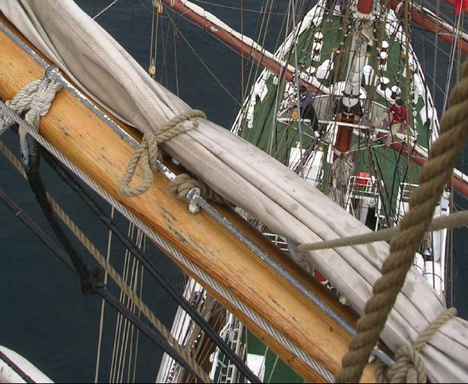
'Searched gaskets, presumably as they were used in 19th c. square riggers, and found: In sailing, gaskets are lengths of rope or fabric used for reefing a sail, or hold a stowed sail in place. In modern use, the term is usually restricted to square-rigged ships, the equivalent items on yachts being referred to by the more prosaic "sail ties". On most ships, gaskets are made of rope. They are attached to the top of the yard and, left loose, would hang behind the sail. Gaskets should never be left dangling, however, so when the sail is set they are brought around underneath the yard and up the back of it and then tied to the jackstay (metal rod) where they originated.
-
'Never thought of that - another good technique to have in one's 'toolbox'
-
To prevent dust, etc. from getting into the fibers of wood decking (exposed horizontally, ergo more vulnerable) over time, I'd only used a single brushed application (sparing) of 'blond' (clear) shellac - or perhaps anywhere from a 1:1 to 1:2 parts 'amber' to clear shellac mix (as desired - experiment first for color). If any fibers are raised, a very light touch with 600 grit paper will do. I happen to like shellac, and denatured alcohol is the solvent. But flat or semi gloss varnish (if not overused) also works. Any additional shellac might produce a 'shiny' finish (but even that can be tempered with 320 grit paper). Note that you won't be able to glue anything to the deck after that (except with CA, but the joint may be weak). Metal eyes needed on the deck should be assembled through the deck before mounting, with the ends of the eyes bent under the deck and epoxied. Fife rails should have extra wood glued under the deck where they go, so holes can be drilled from above to insure a strong glue joint. There are few things as frustrating as weakly attached fife rails that pop-off after a model is finished.

