


yvesvidal
-
Posts
3,489 -
Joined
-
Last visited
Content Type
Profiles
Forums
Gallery
Events
Posts posted by yvesvidal
-
-
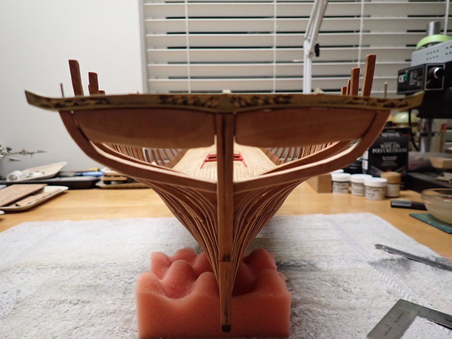
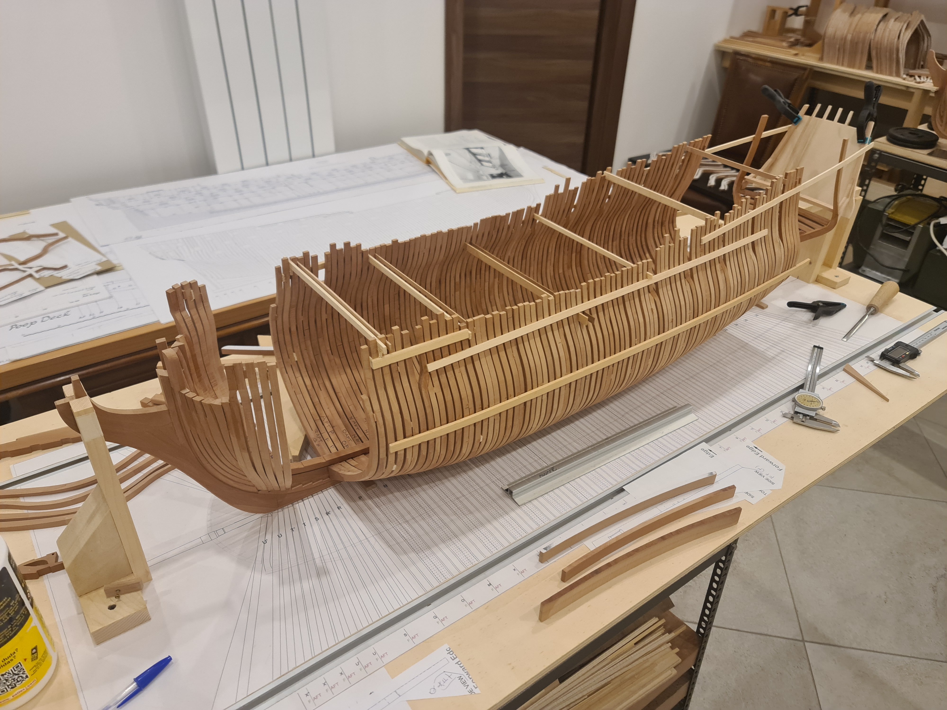
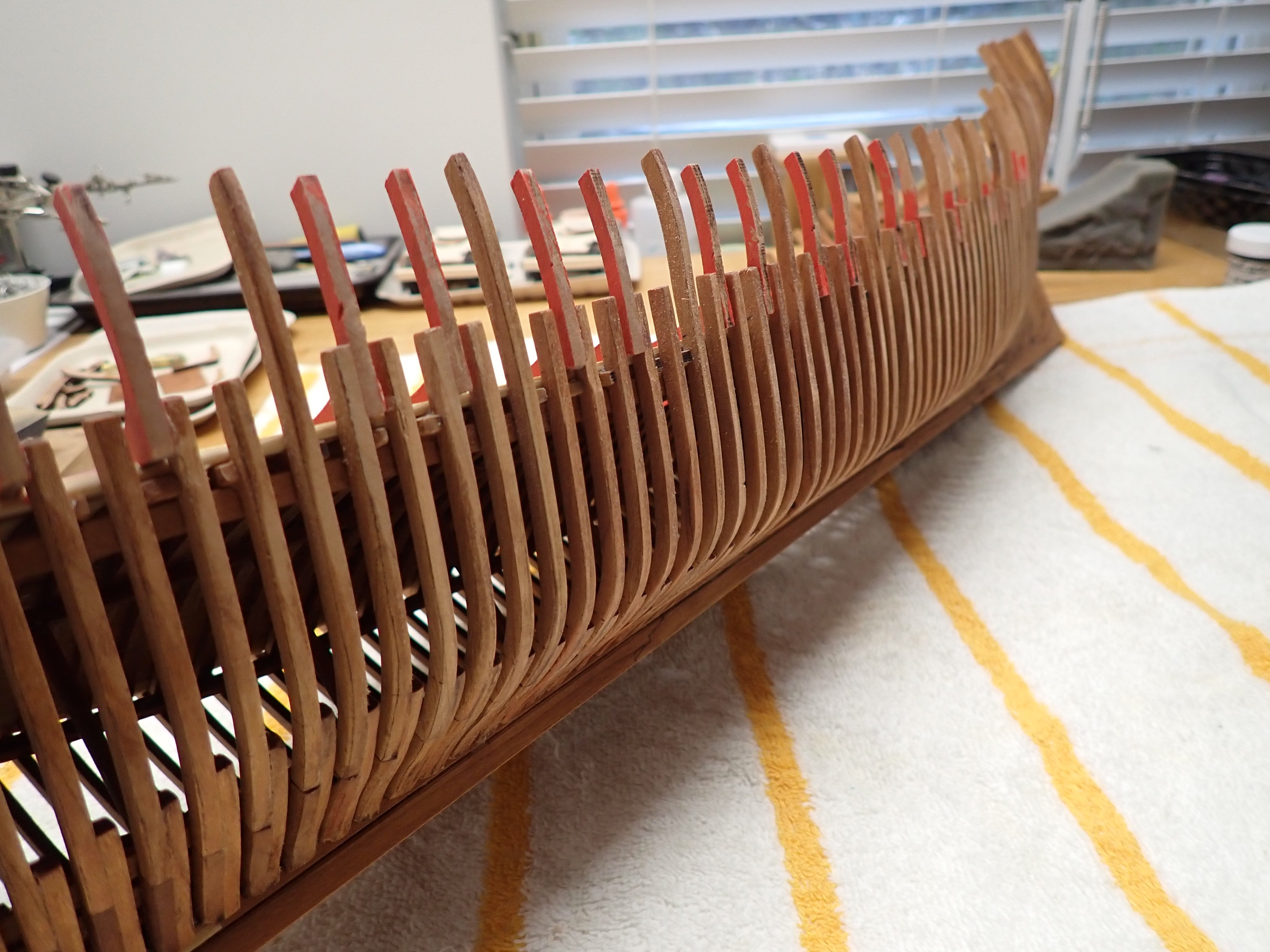
Before moving further with the planking, I have decided to take a look at the gun decks and see how these are being built.
There is nothing easy on that model, as we have nothing flat and straight, besides the bottom of the keel.
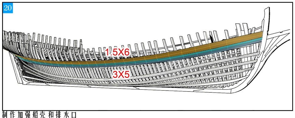
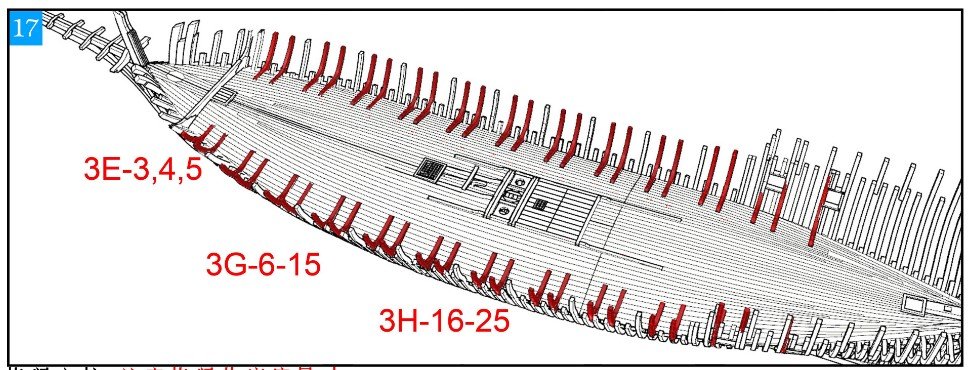
As always, the instructions are scarce:
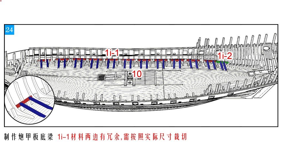
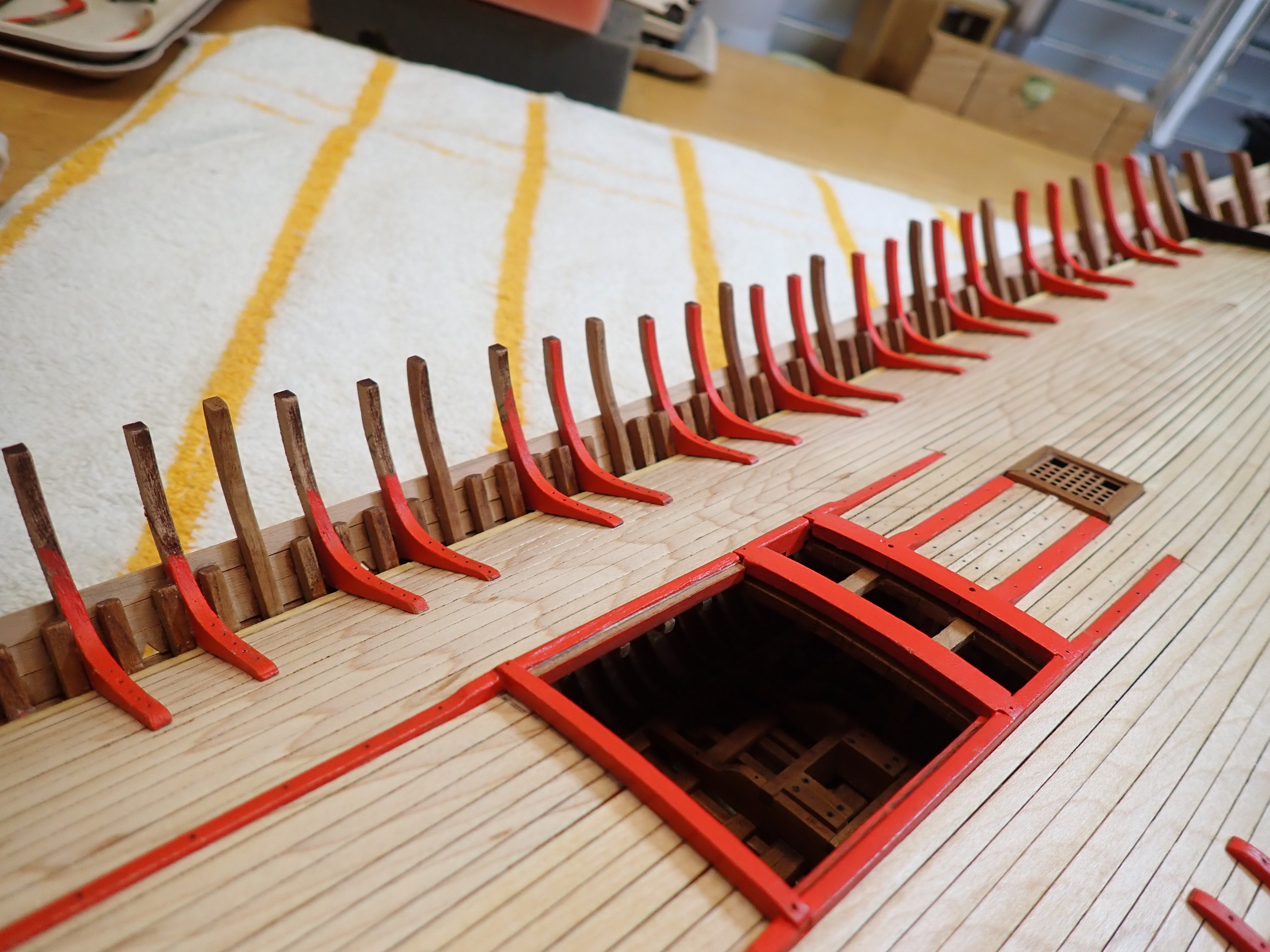
The Chinese ideograms are simply indicating that you can cut the blue parts to the correct length. Thank you. Nothing is really being said about where the red parts are to be sitting against the frames and the plan is of little use as well. So, after digesting plans, Monograph and the above picture, I decided to place them so that the gun deck would be horizontal as much as possible.
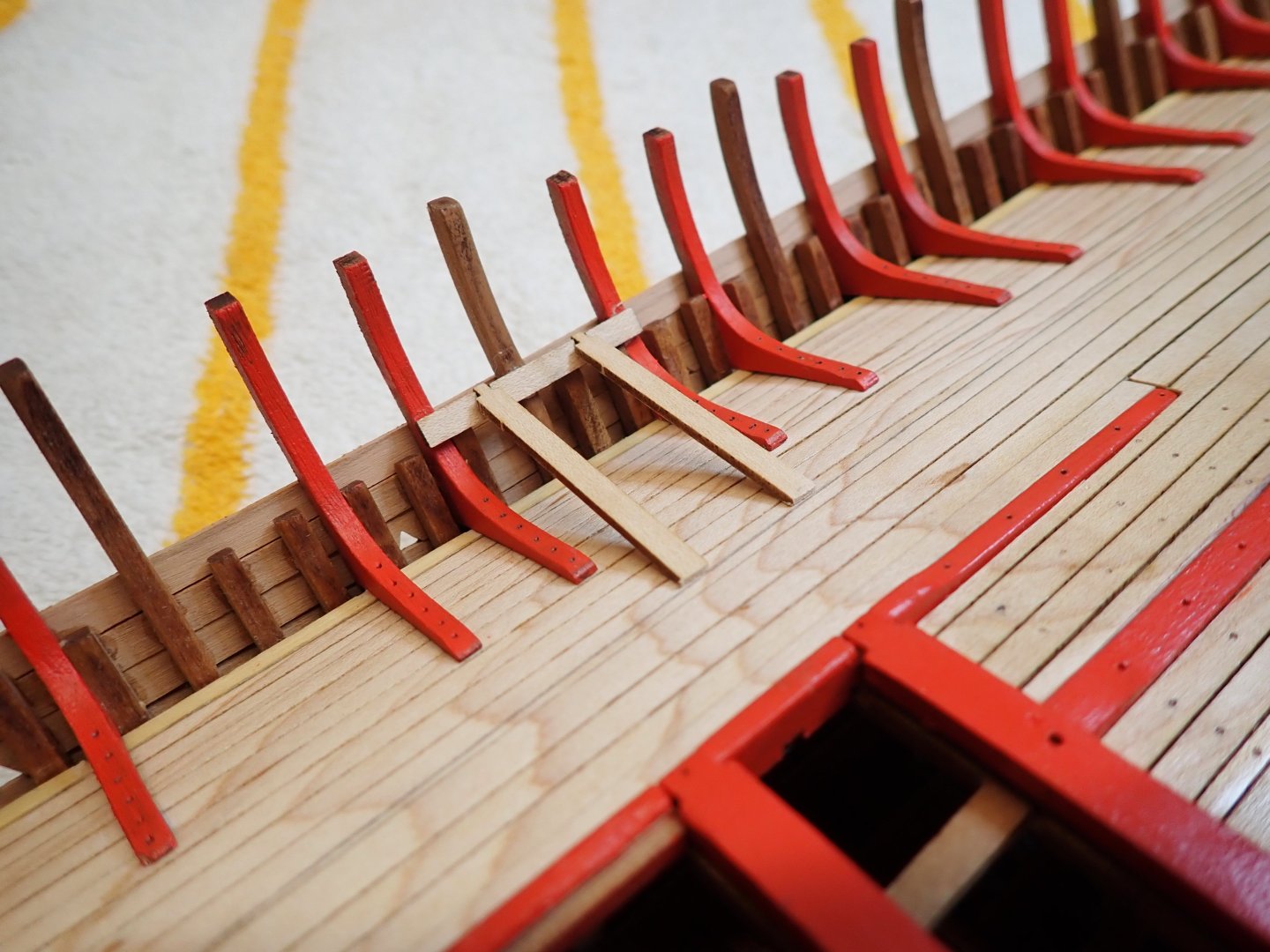
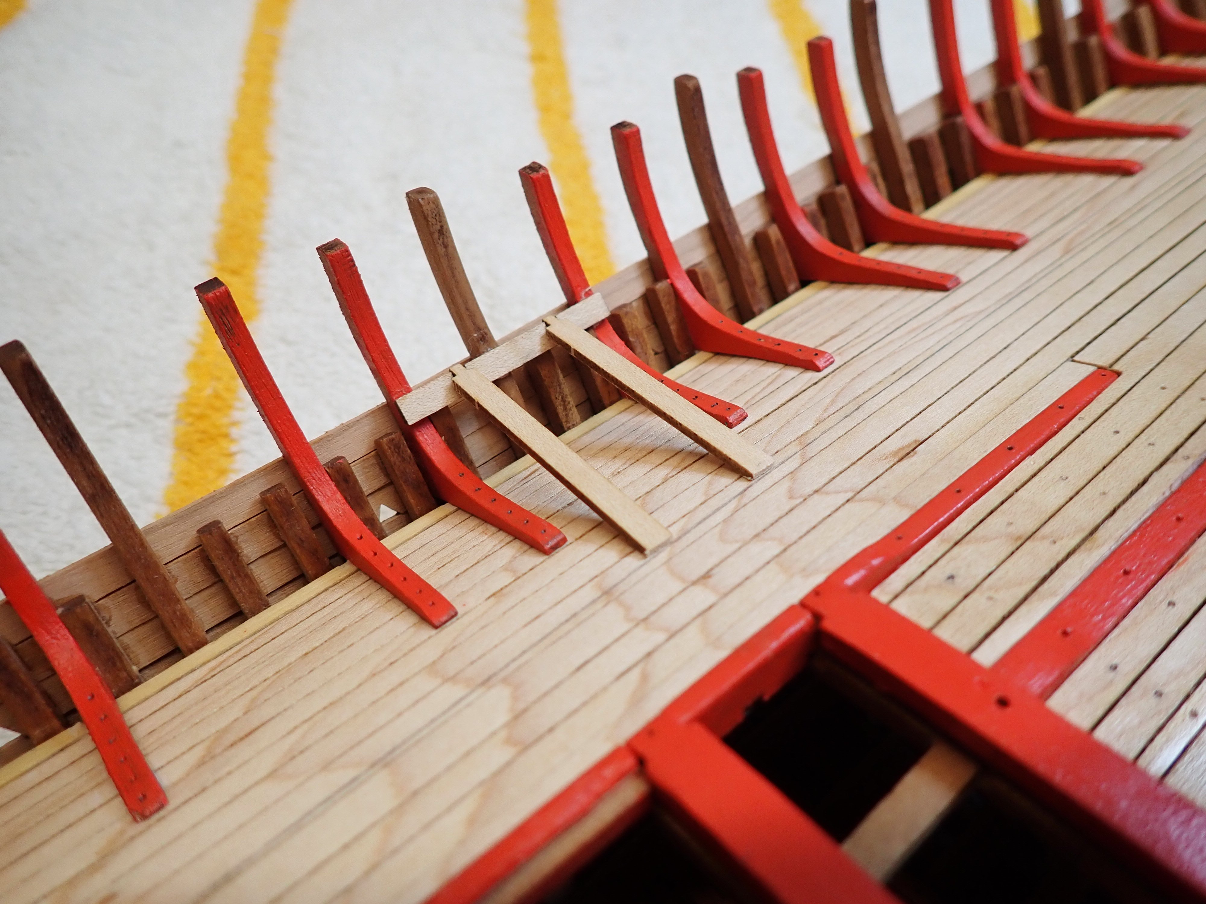
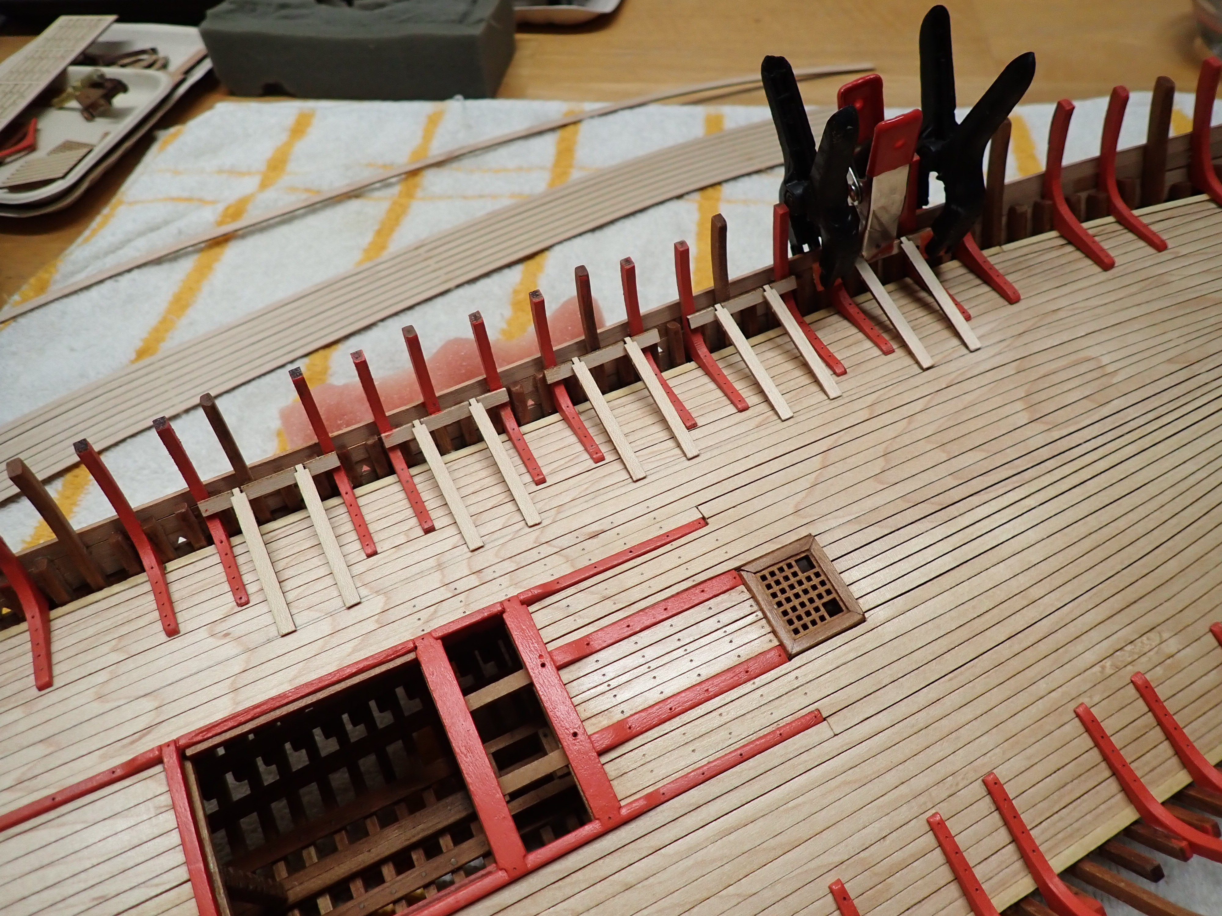
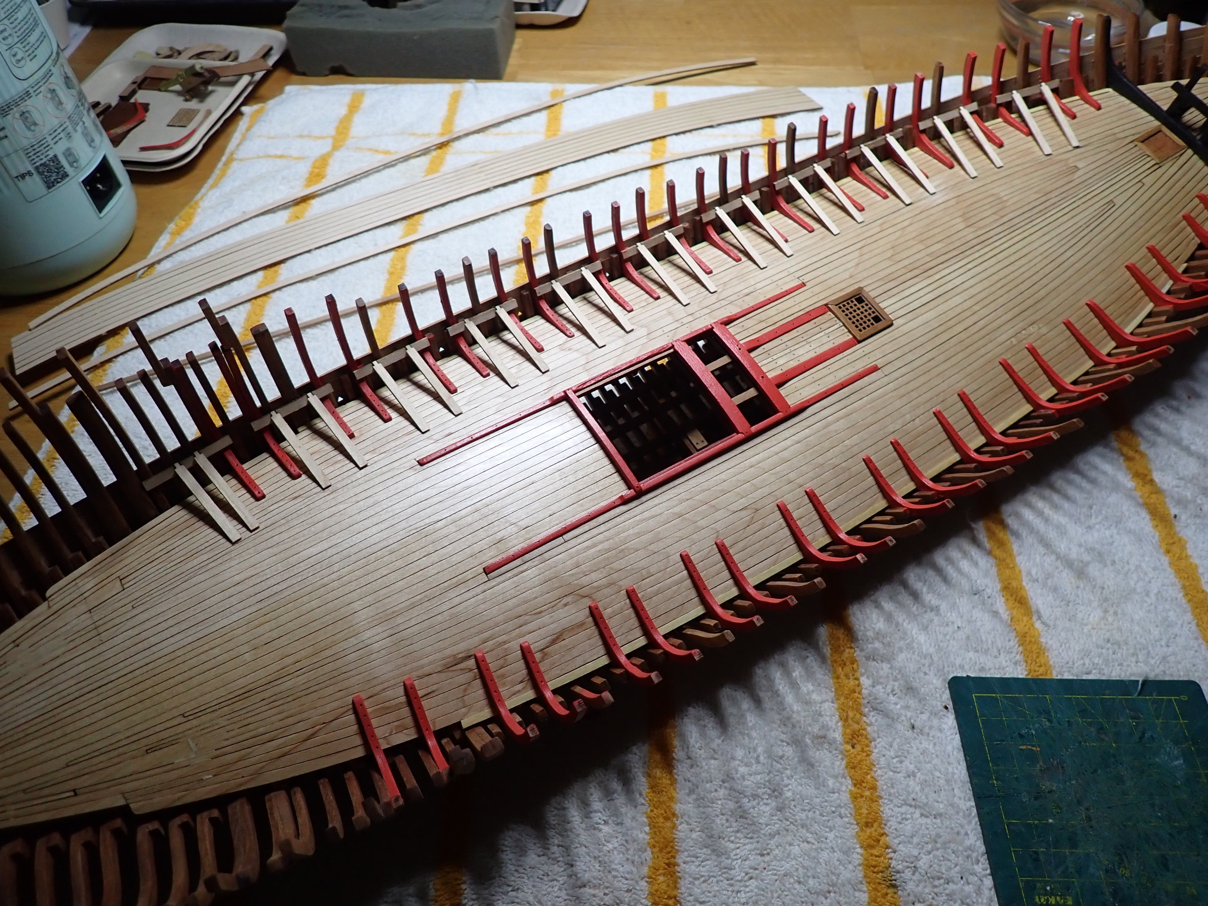
I traced a delineation line on the deck, using the gun deck planking provided in the kit. That line allows me to determine the length of the support bars.
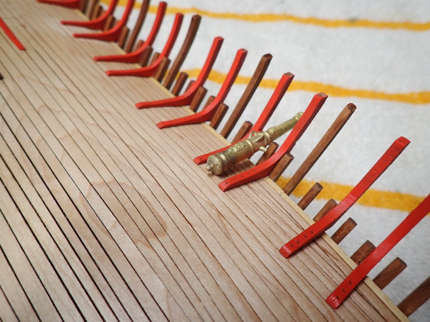
After installing a gun on the support bars, the gun seems to be about horizontal, so it may work.


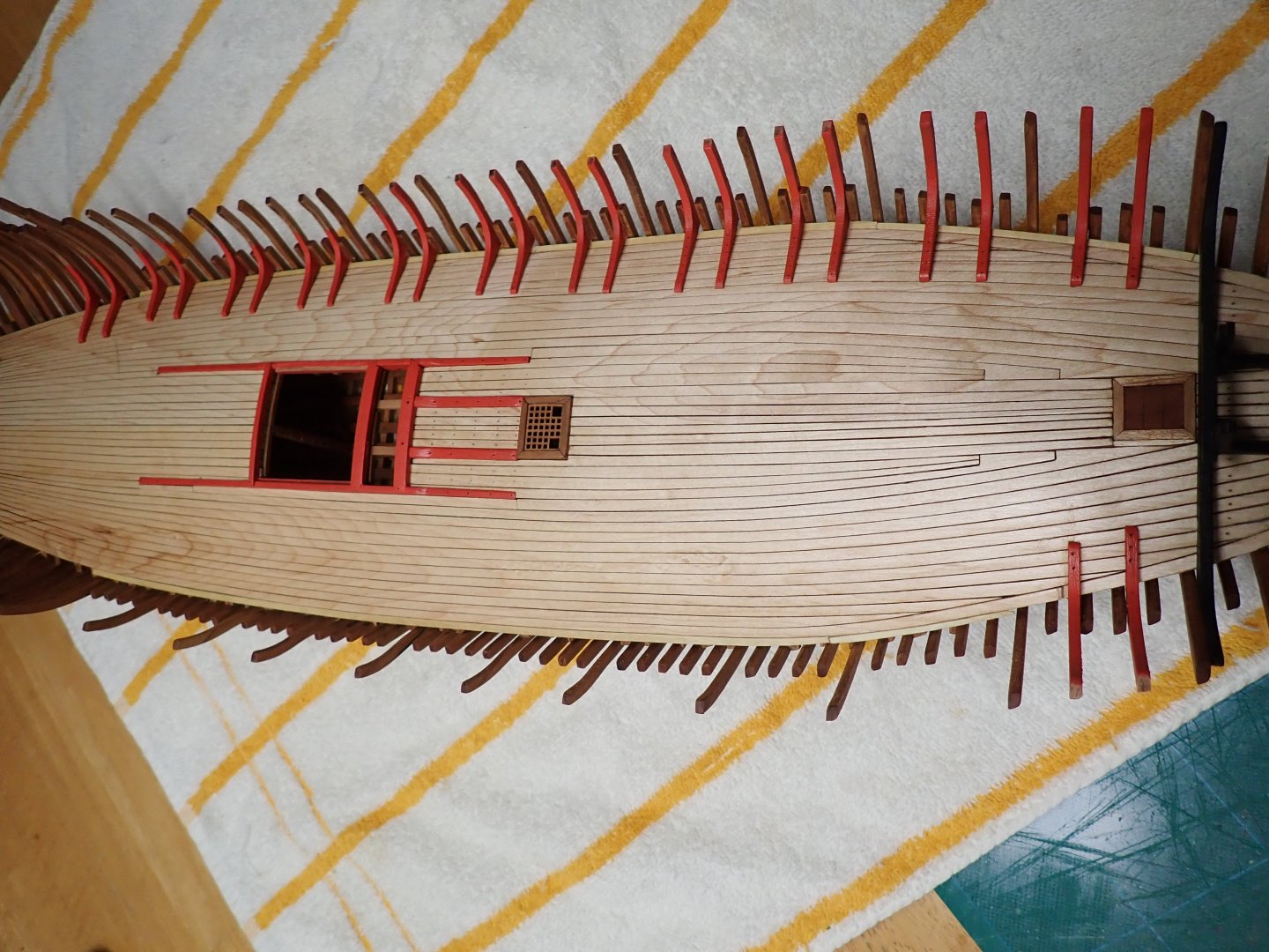
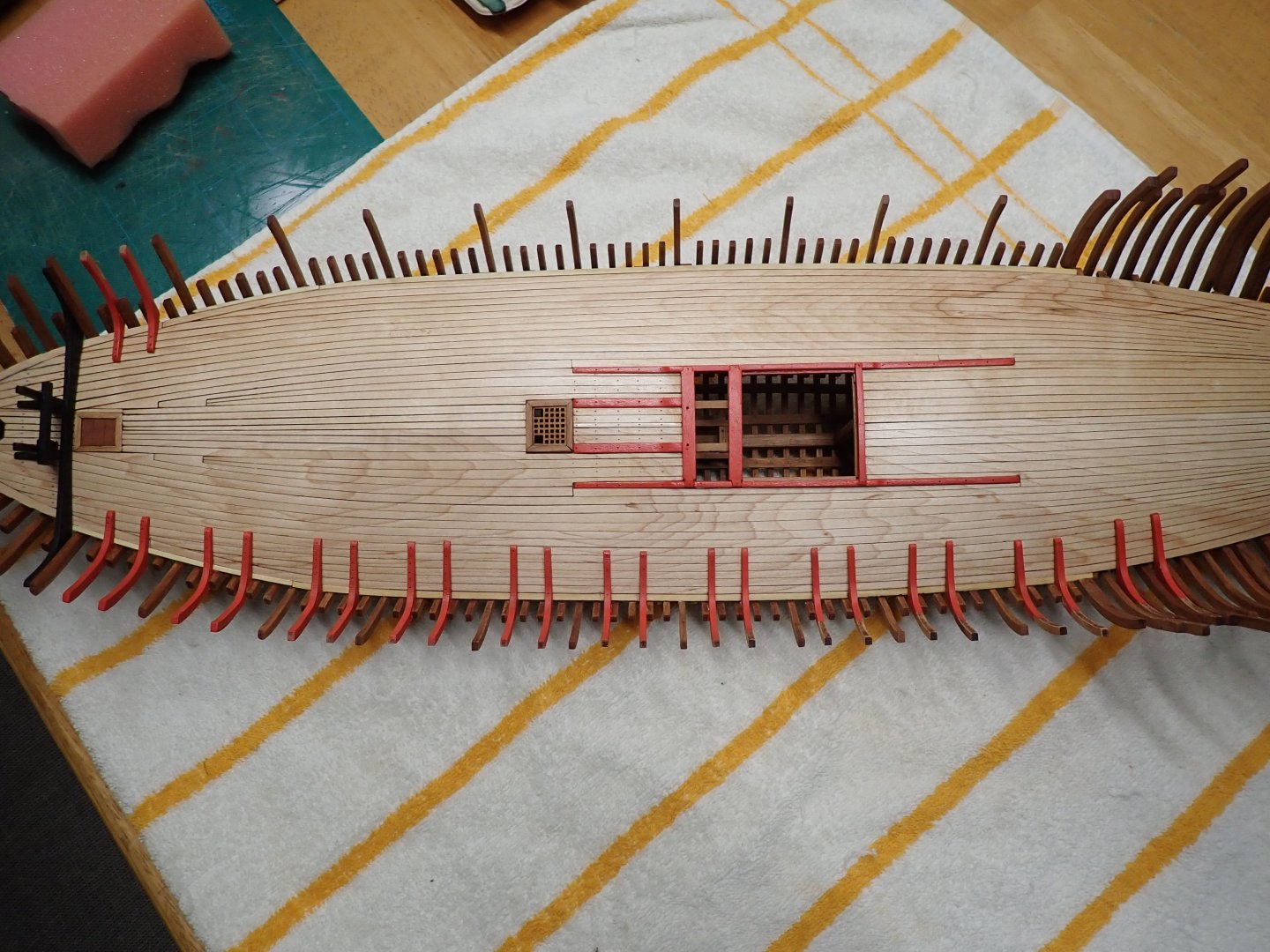
At this stage, all supports have been installed and the planking seems to fit nicely, more or less.
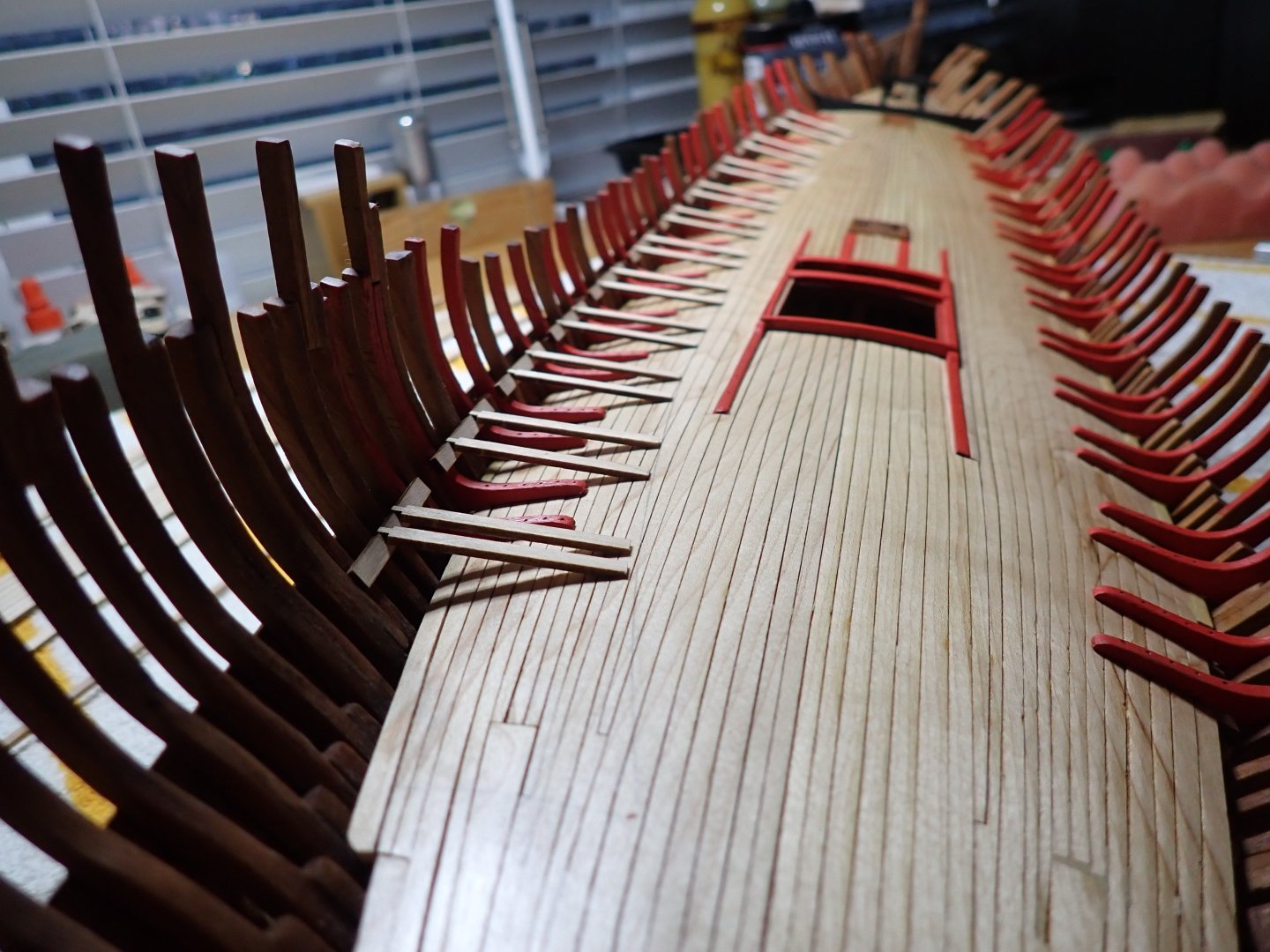
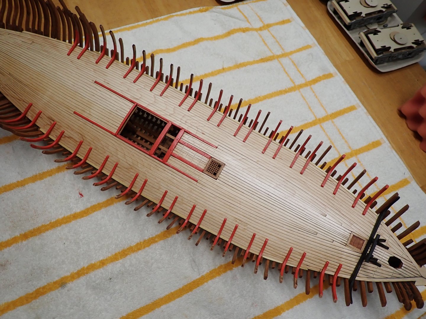
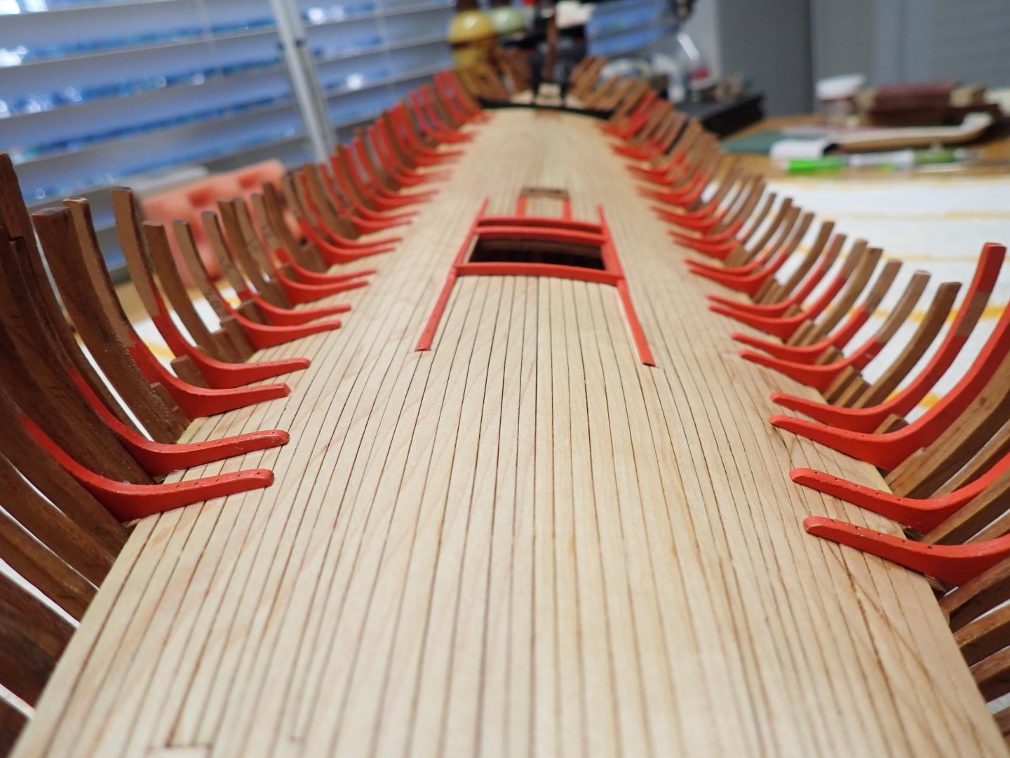
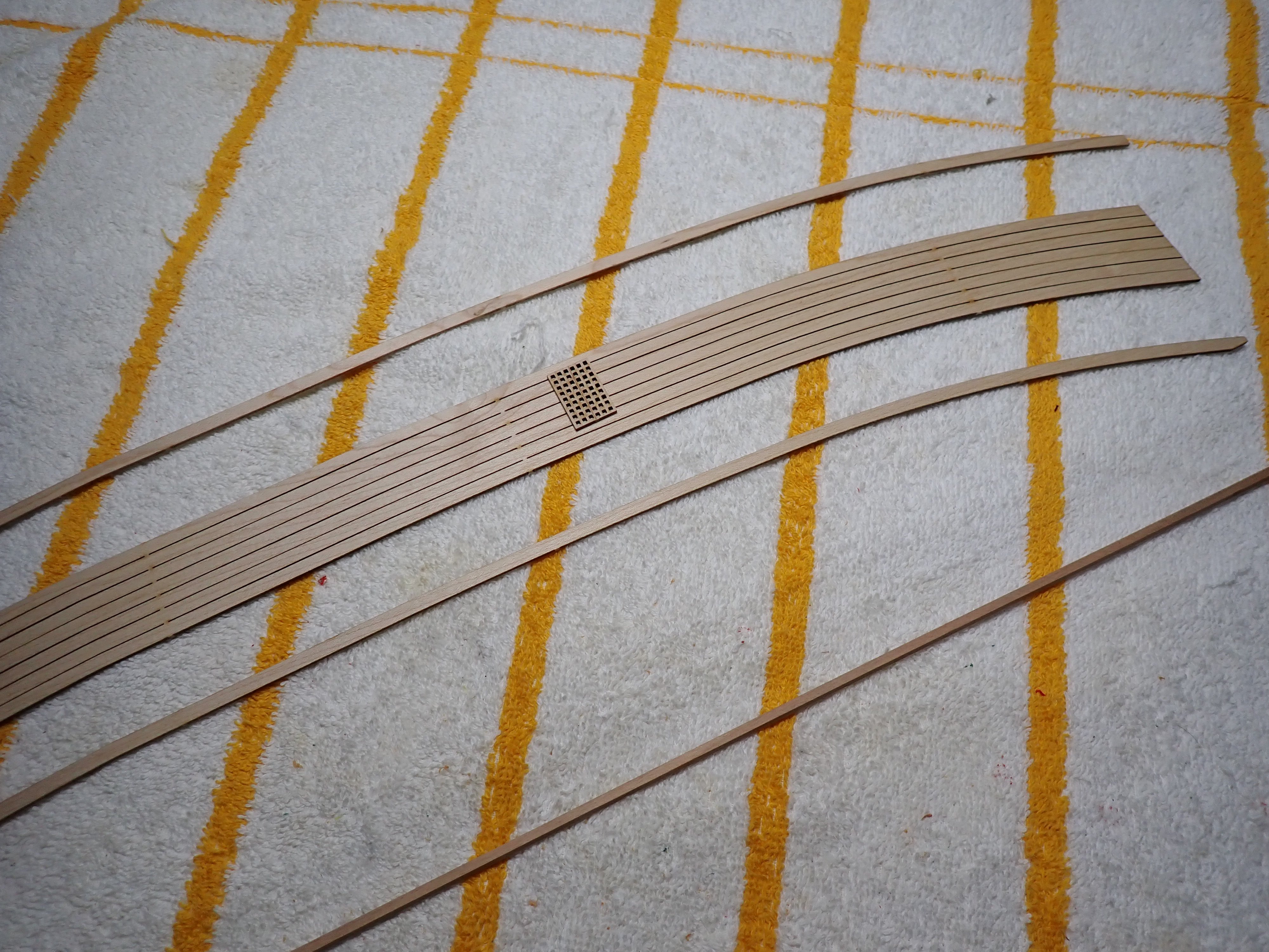
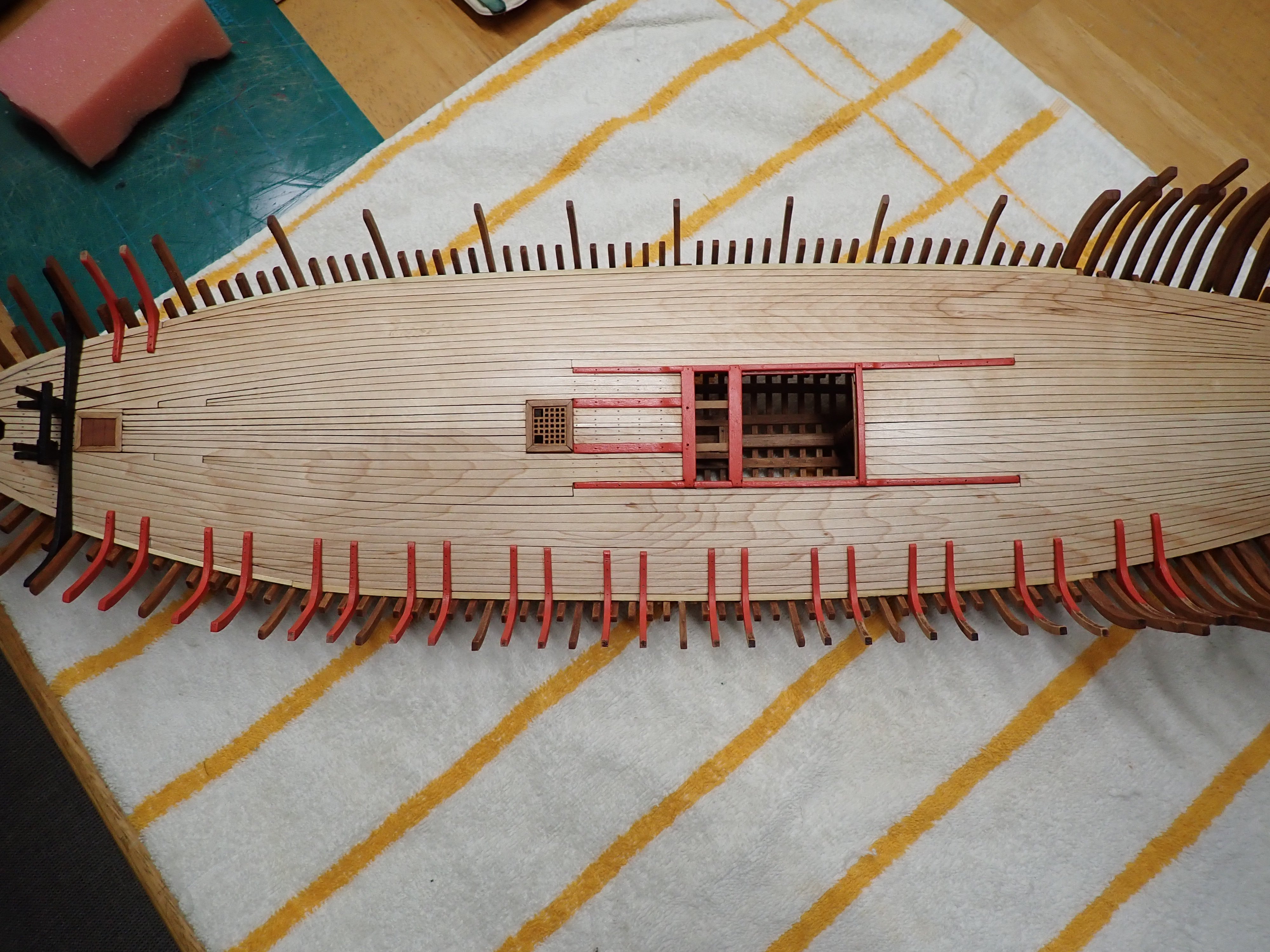
The picture above gives a clear understanding how this ship is architectured. With such a convex deck, platforms to hold the guns were absolutely necessary. The picture below shows the upcoming gun deck planking. It is composed of 9 planks and 9 grates which are sitting on the deck supports. There will be a lot of cutting and fine adjustments to make it look decent.

In the meantime, I am painting the bulwark in red, as the Monograph seems to indicate. That is done in a much easier way by limiting the height of the hull planking. With this kit, you have to approach the various tasks in a scrambled and mixed way.... Not easy!! Have I said that before?
Yves
- Nearshore, wvdhee, KARAVOKIRIS and 6 others
-
 9
9
-
I think it needs an extra coat of clear....
Yves
- KeithAug, Keith Black, vossiewulf and 3 others
-
 6
6
-
-
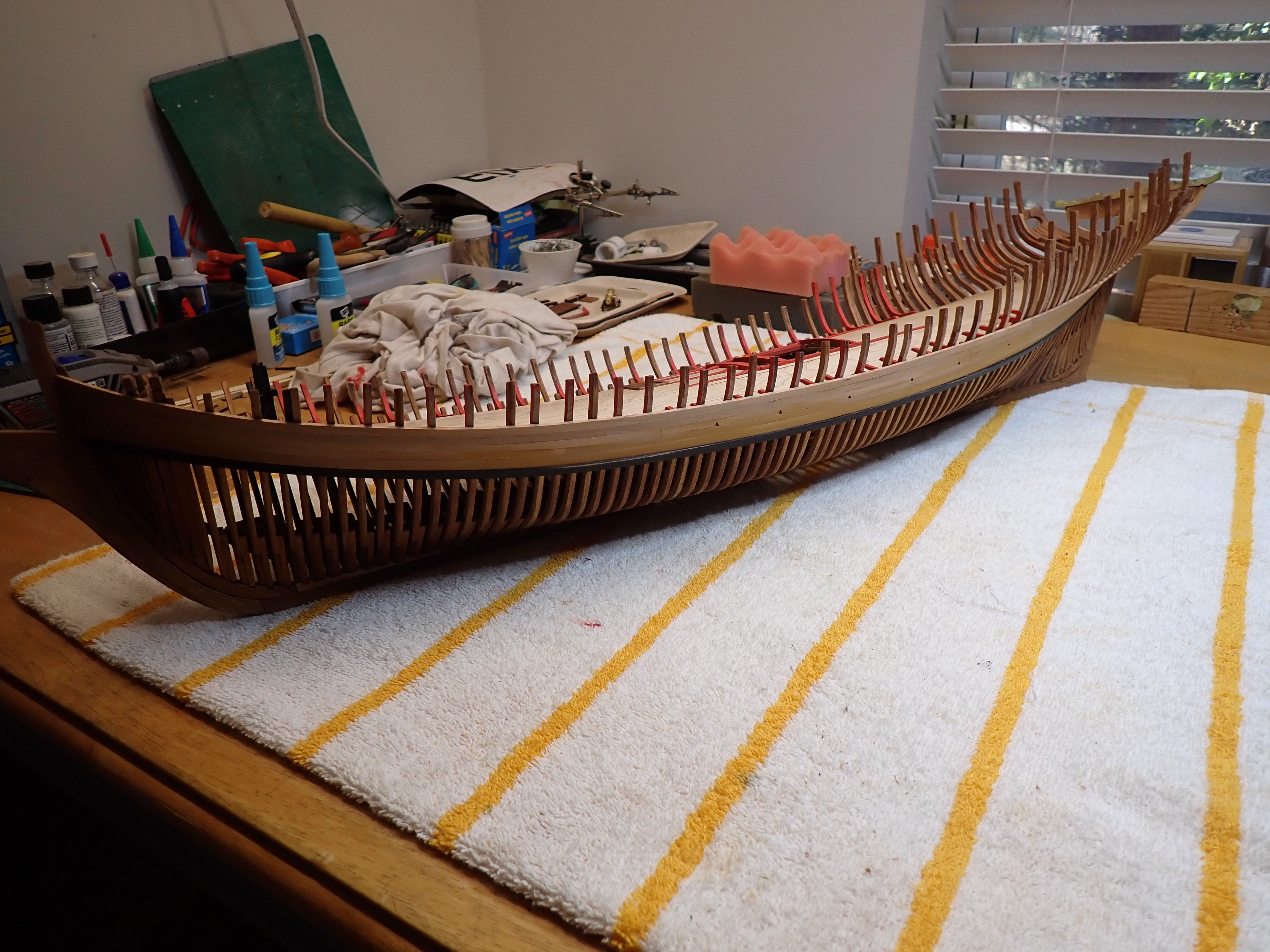
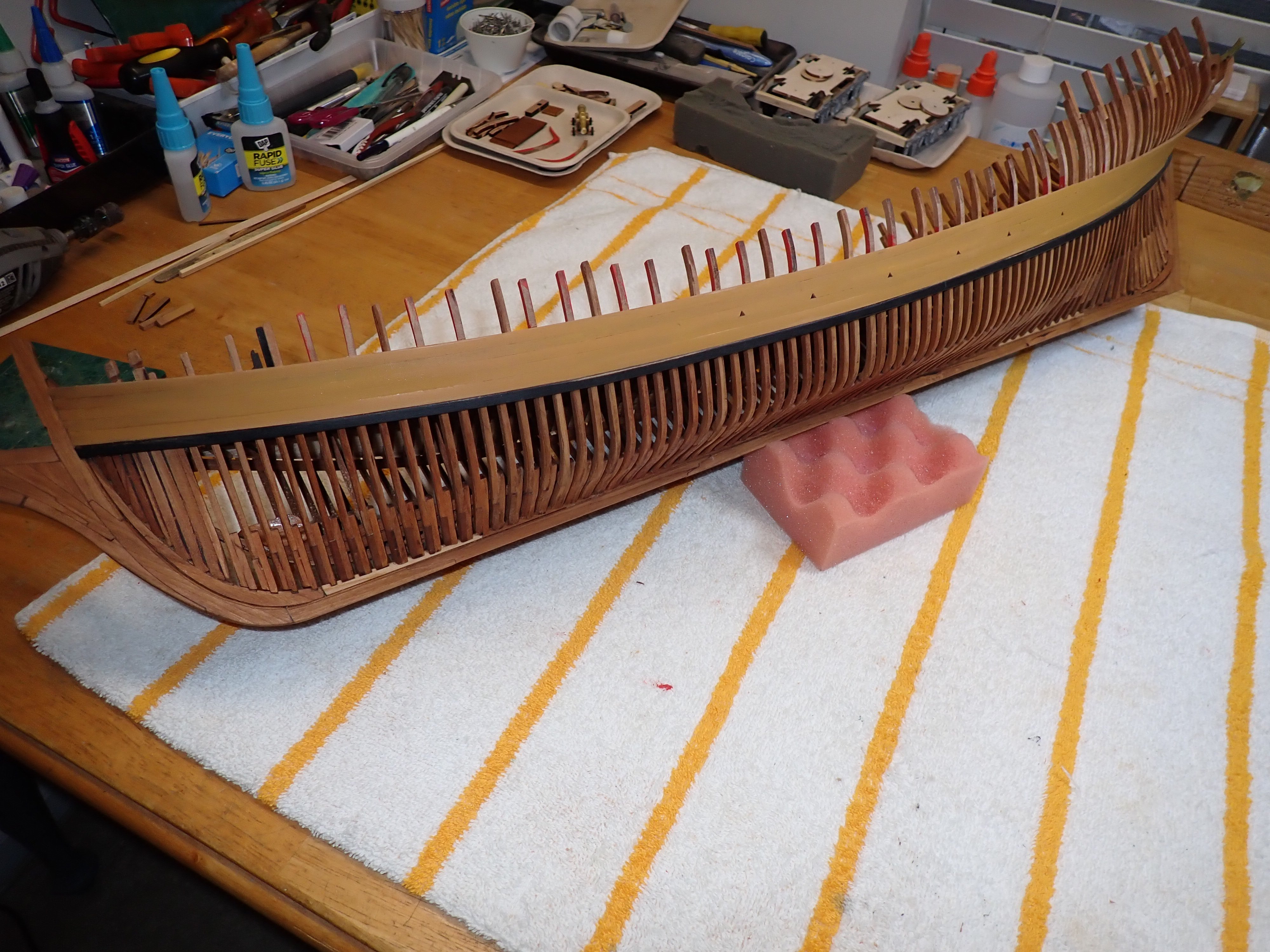
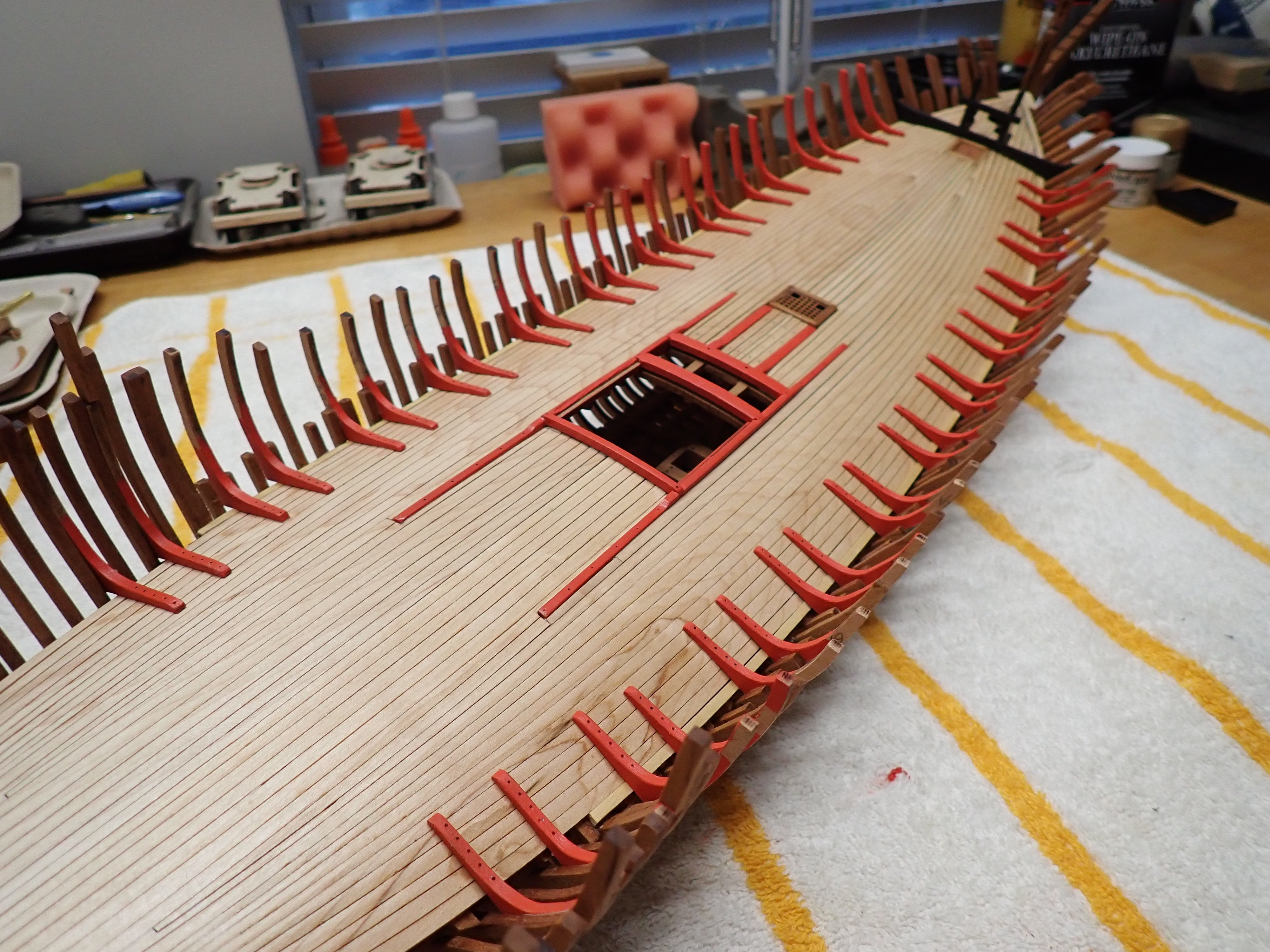
Before moving further, I am planking one side of the ship to get a better grasp on how the guns decks are positioned and built.


With a coat of Model Shipways Yellow Ochre:

I still have to sand a little bit the planking...
The following picture shows the deck and where the gun decks will be built:

That will be for another update.
Yves
-
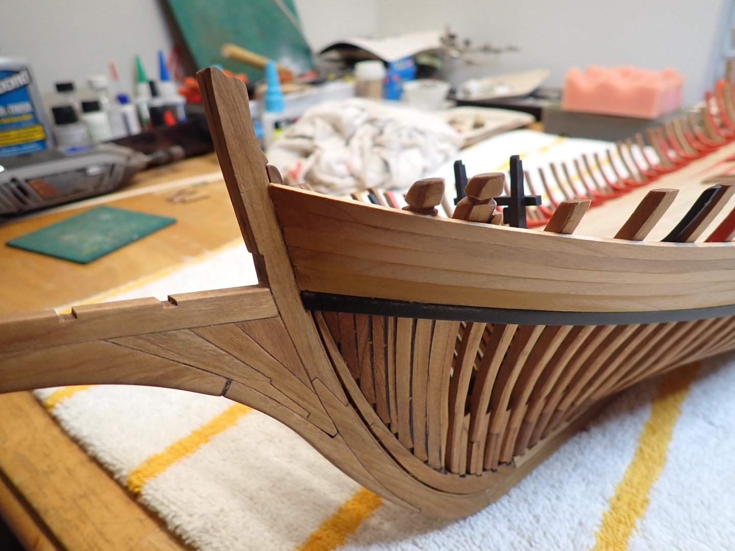
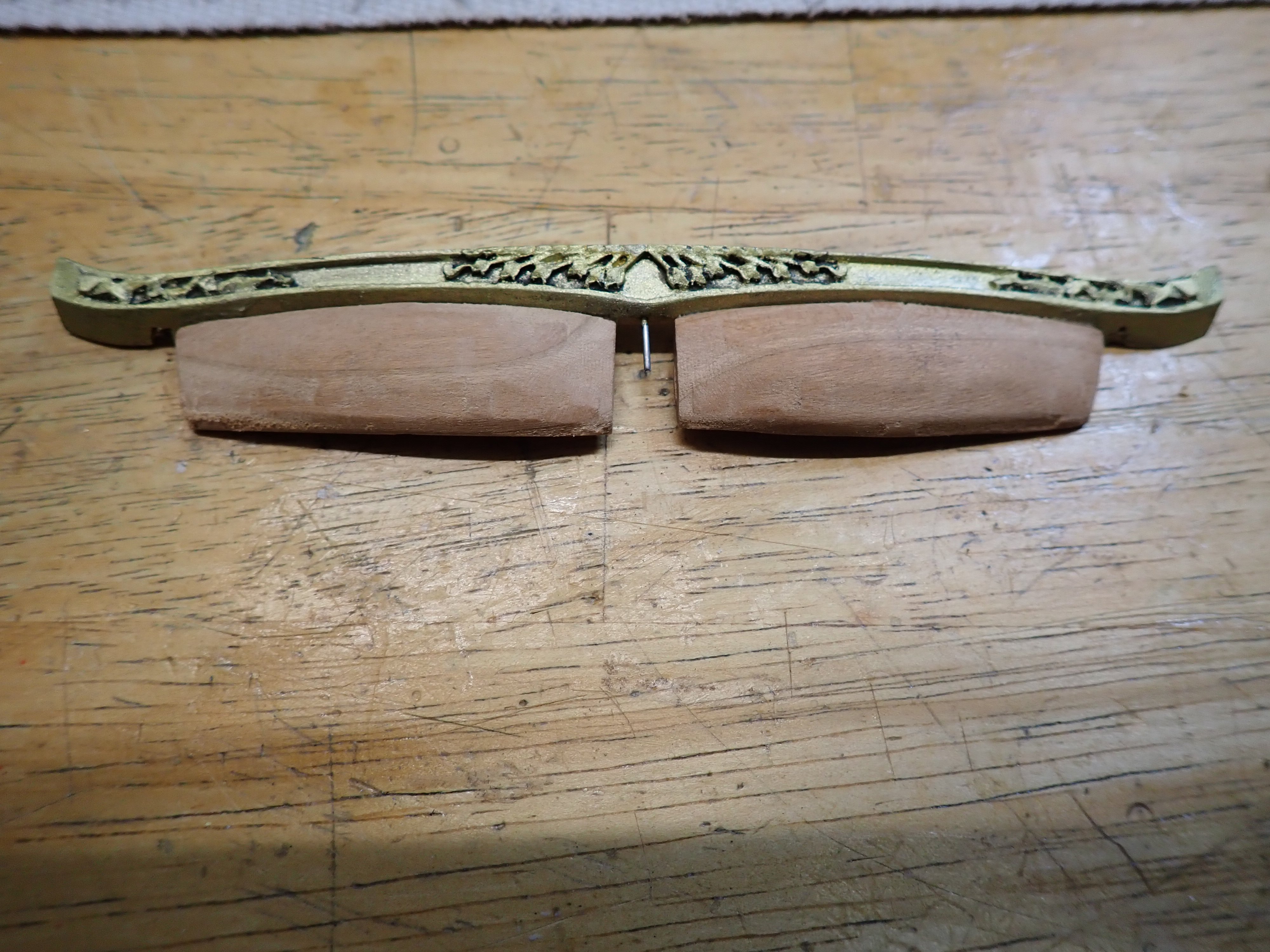
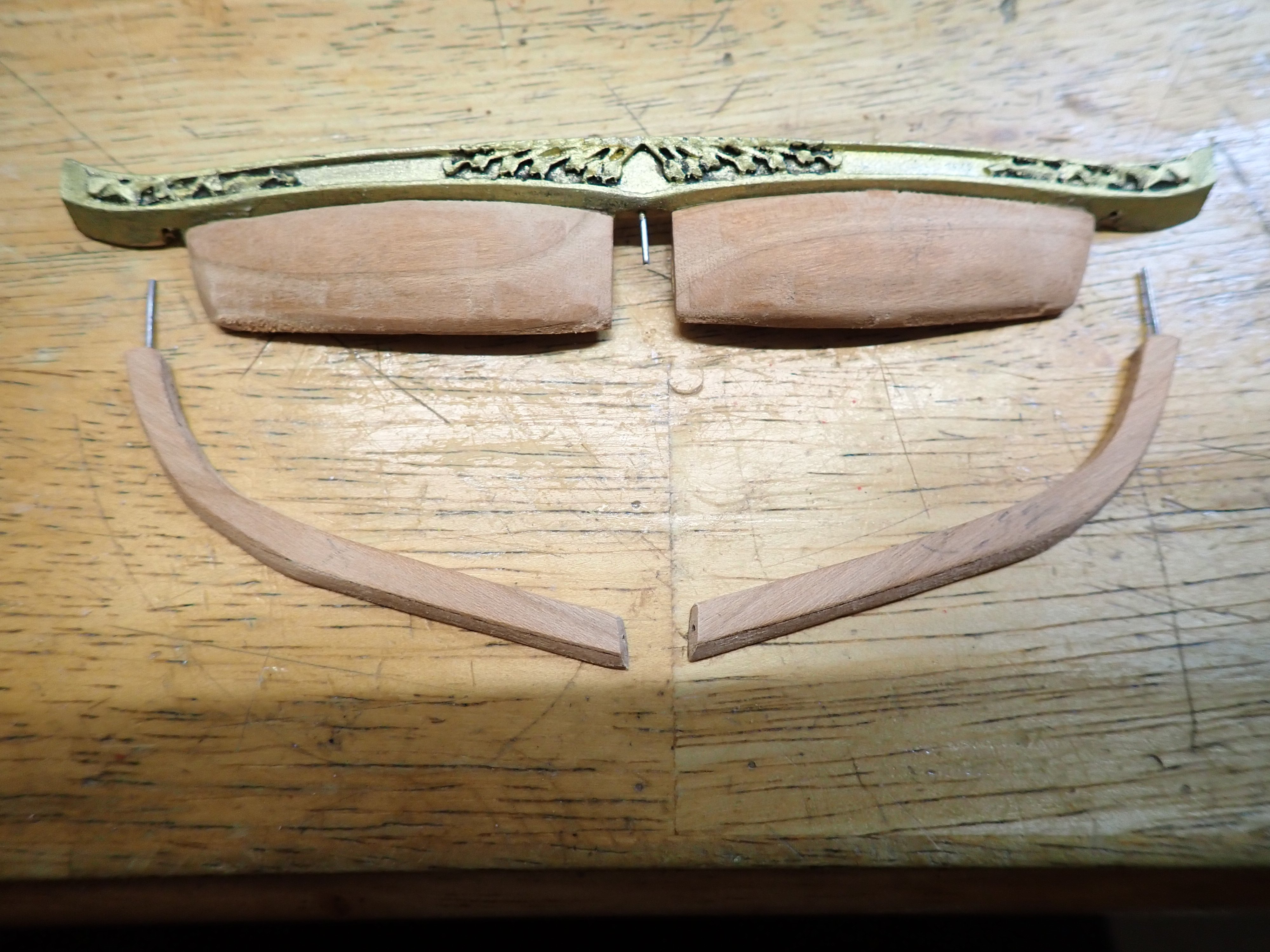
Before doing the planking, I finally resolved to build the stern. It is not easy at all, and nothing has been designed in the kit to help the novice modeller.
I will present what I have been doing so far. At times, it felt like flying in the clouds without any IFR instrumentation.
First the instructions:
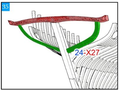
The plans do not bring much details and confirms that the freeze must be flush with the rear keel. Otherwise the rudder will not fit.
Because nothing will hold by itself, I had to resort to pinning the parts:
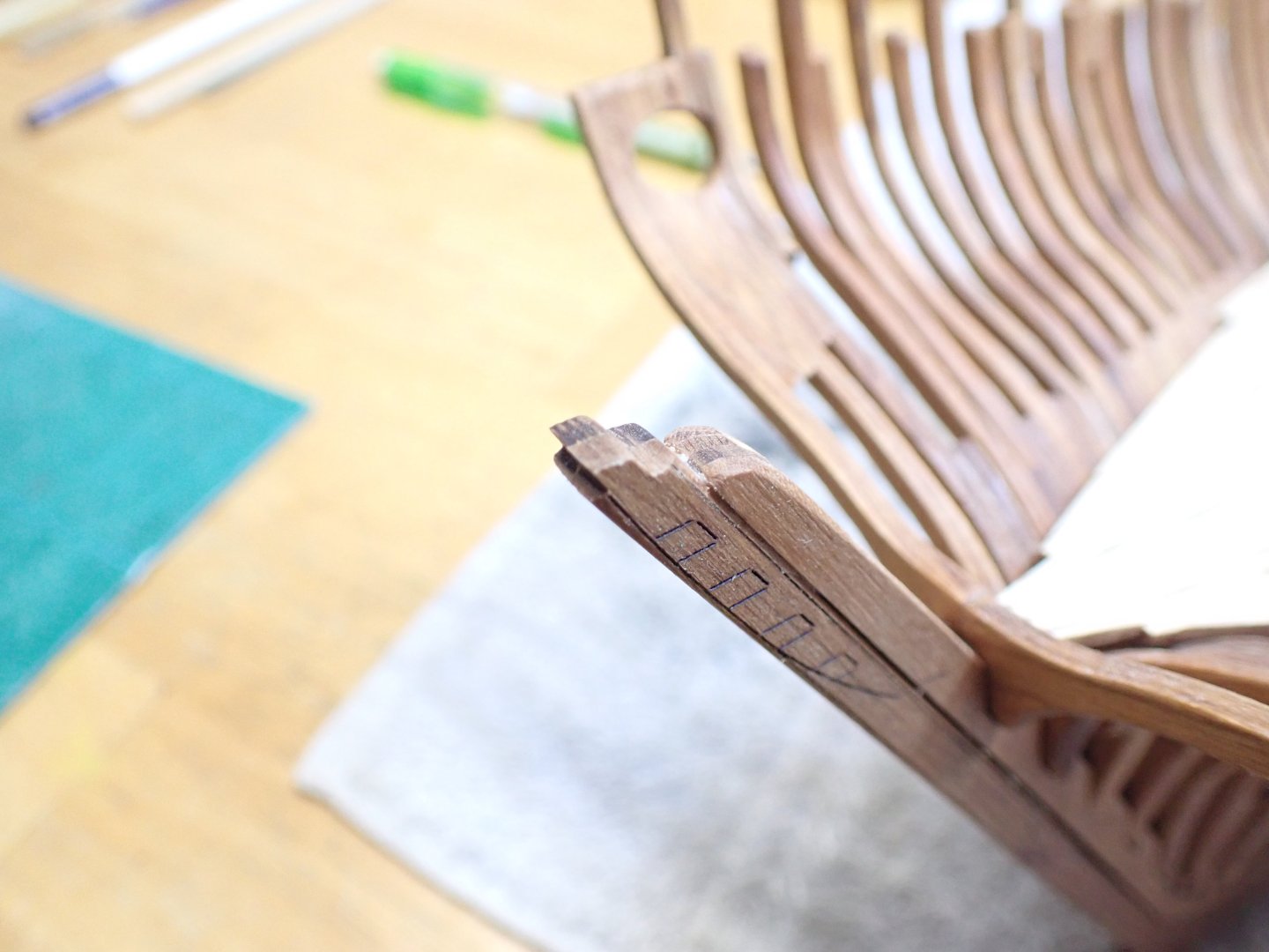
The instructions provide two ways of assembling the stern. I am going with the easier path:

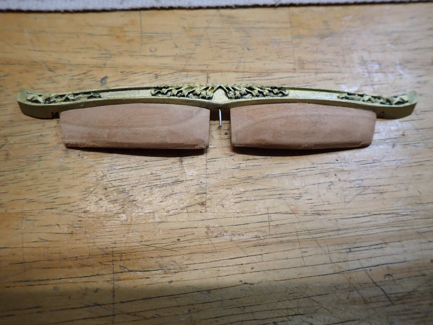
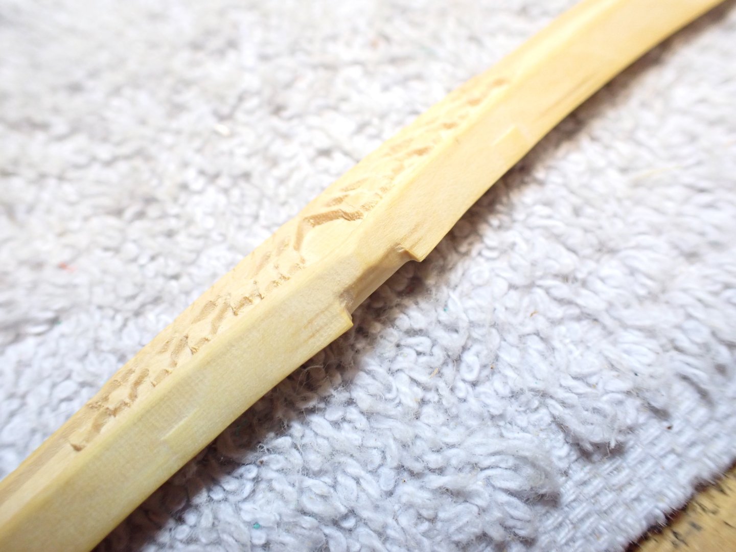
You can see one of the pins that is used to attach the parts (above). More pins are introduced to hold every single part (below):

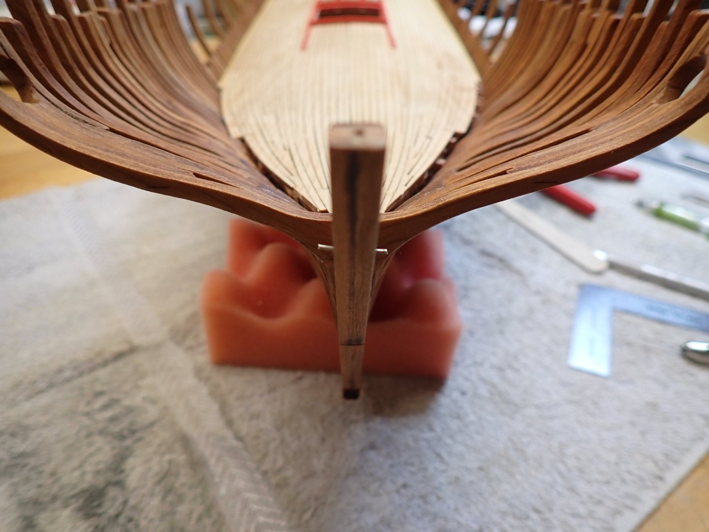
Final assembly....
Once glued and dry, the assembly is surprisingly robust.
Yves
-
-
Are you happy with the plastic wheels? It may be possible to get some 1/32 Gauge 1 replacement axle that may work on the rails provided in the kit. Or simply replace the wheels for better rolling capabilities (metal wheels).
Two problems: 1) It may be expensive to purchase so many wheels and 2) they may not fit the diameter of the axles provided in the kit.
Anyway, I doubt that you will be moving much that massive artillery piece. How does the carrier move on the rails?
Yves
- thibaultron, Egilman, king derelict and 2 others
-
5
-
-
Craig, just buy a cheap digital camera with a USB-C interface that you can connect to your computer.
That will do it.
Yves
- Egilman, Canute and Old Collingwood
-
2
-
1
-
I completely agree with Rob. So close to the pier, only small speeds and almost no wake can be acceptable.
But again, this is your diorama and you can do what you like. 🙂
Yves
- king derelict, Canute, DocRob and 2 others
-
5
-
4 hours ago, Blibul said:
For those unfamiliar with how both old and modern planes are controlled, here are some sketches I’ve made to help explain or clarify.

I think you have the UP/DOWN reversed. Pulling the stick will decrease the tension on the red wires, leading to the plane diving....
Yves
- Canute, Old Collingwood, thibaultron and 1 other
-
4
-
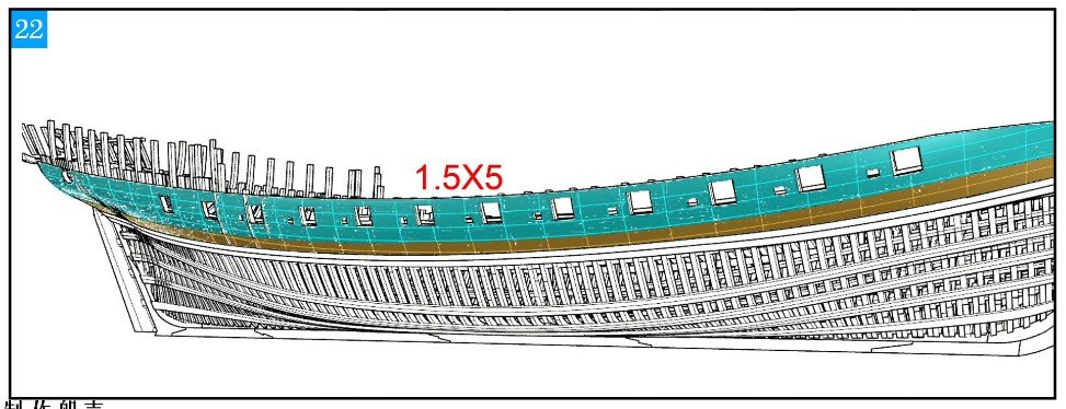
I started some planking on the hull, on one side only. This is what the instructions are suggesting:
This vessel is not really equipped with Wales as found on more traditional builds. It has some kind of belt on the low side of the hull and a thinner planking above. I tried to look at different implementations of the Chebec in various museums and galleries and they all seem to show a very thin belt, painted in black. The rest of the planking is the famous "Yellow Ocre" found on a lot of ships towards the end of the XVIII century (according to the Monograph).
The shape of that hull is throwing me off, as I am more used to the British vessels of that period. The belt may be a tad too low on my model. We will see how it goes.... Besides section cuts, the plans are not very clear about where exactly that belt plank is supposed to be.
Yves
- Matt D, JeffT, scrubbyj427 and 12 others
-
15
-
Congratulations on finishing this difficult kit. Now, if you are in Love with the Arizona ship, you can try doing the Trumpeter 1/200 model.
That will be quite different from the Revell kit.
Yves
-
I am glad that you decided to convert the kit to 8 carriages, instead of keeping the simplified version of the kit.
In the long run, it will be worth it.
Yves
-
17 hours ago, hamilton said:
Such a nice sleek hull...
hamilton
Yes, it is such a beautiful ship. Pilot boats had to be quick and very maneuverable.
Yves
-
Oh yes, it will keep its shape for years. I have used that technique on a couple of models and they look like on the first day.
Yves
-
Kevin,
Please, make sure that you present the kit with pictures of the parts and sub-assemblies. Not many of use will be in a position to assemble that monstrous kit and we will be following your Build Log with a lot of interest.
Here in the USA, Squadron published a short video about the kit, showing some of the elements of that massive kit:
Thank you Kevin.
Yves
- GrandpaPhil, hof00, Kevin and 5 others
-
8
-
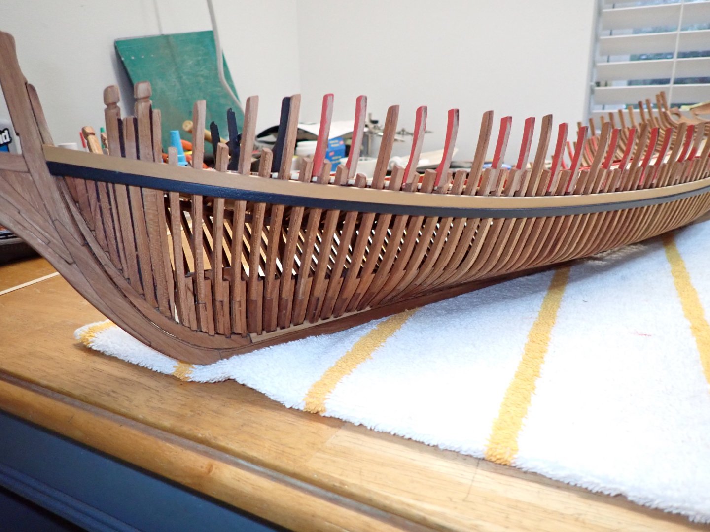
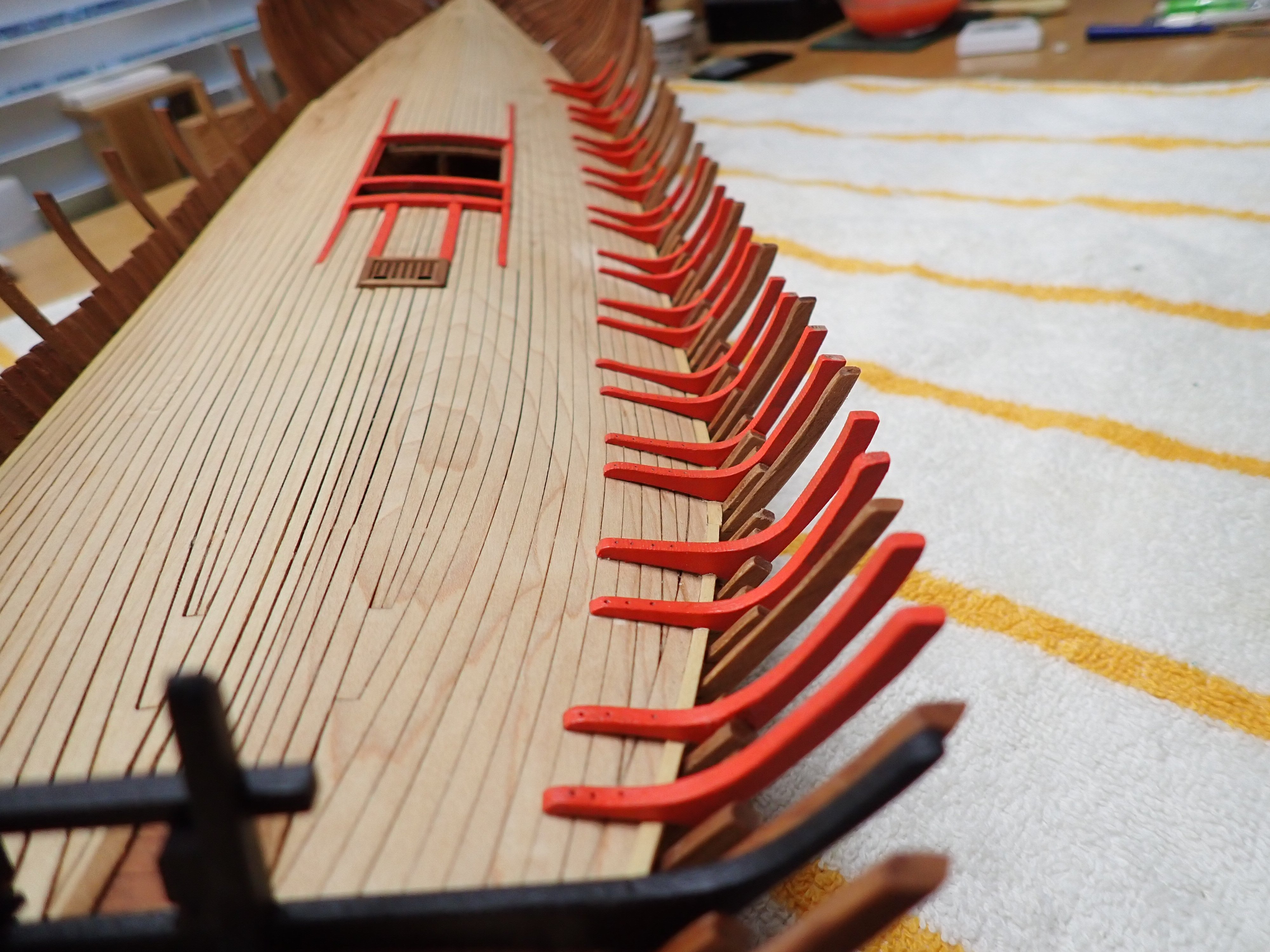
I finally completed the installation of the bulwarks supports:

The next step is a little bit fuzzy for me as I cannot find where it must be installed exactly. The plan is not showing anything and it needs to be addressed very carefully. So, I am going to start fairing the hull and the bulwarks and try to install the wales and some planking. Then I will be back with the gun decks and that will help me.
Yves
-
Finally, a decent size model. Kevin, you have to start planning for a larger garage or display room.....
Don't forget to use real PECO Gauge 1 rails for realism and to procure two Marklin BR 86 engines in Gauge 1 to pull it.
That should be an exciting Build Log.
Yves
-
That's it, full transition to 3D printing with just a few wood parts.....
We now talk about Wood Etched (WE) parts as an addendum to the resin core.
Good job on this little vessel.
Yves
- thibaultron and hollowneck
-
2
-
Those cap rails bring a feeling of completion.
Yves
- Keith Black, Canute and ccoyle
-
3
-
Thank you Javelin and gsdpic. I have been able to find something on Da-Bay that may fit the bill.
Yves
-
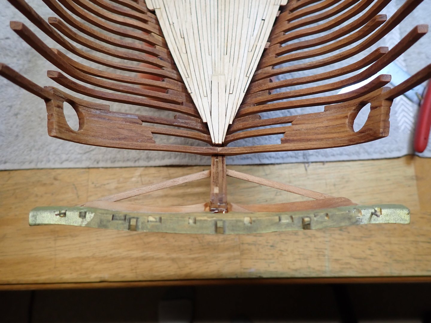
I need to ask a question: where do you find the brass stands used to display a model such as this one?
The thickness of the keel is 8 mm, so these stands would have to be fairly large to accommodate the keel, on their receiving ends. I am not planning to install any screws or bolts into the keel but just provide two longitudinal stands for the keel and two side stands for stability, under the hull.
I welcome your thoughts and suggestions.
Yves
-
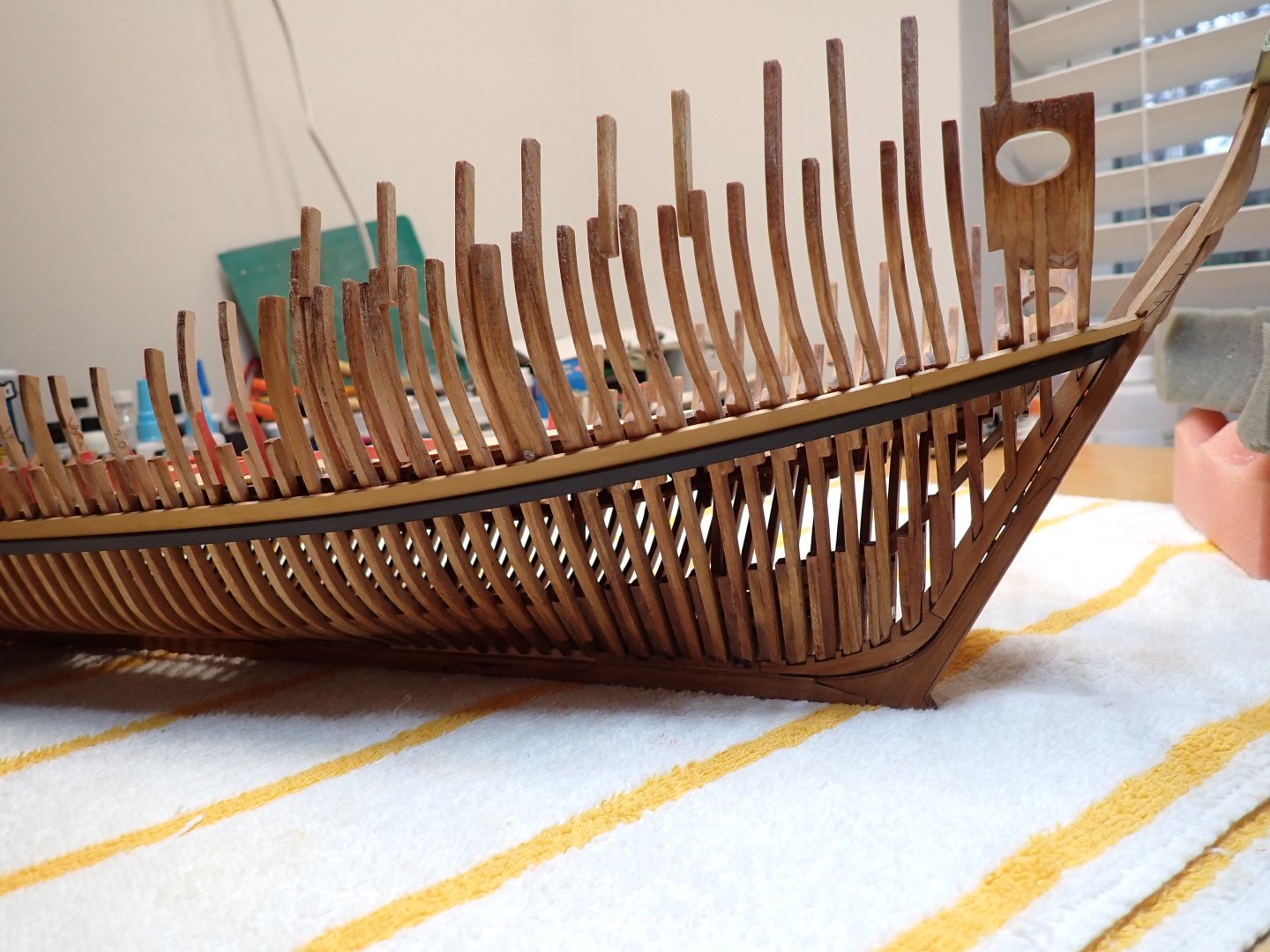
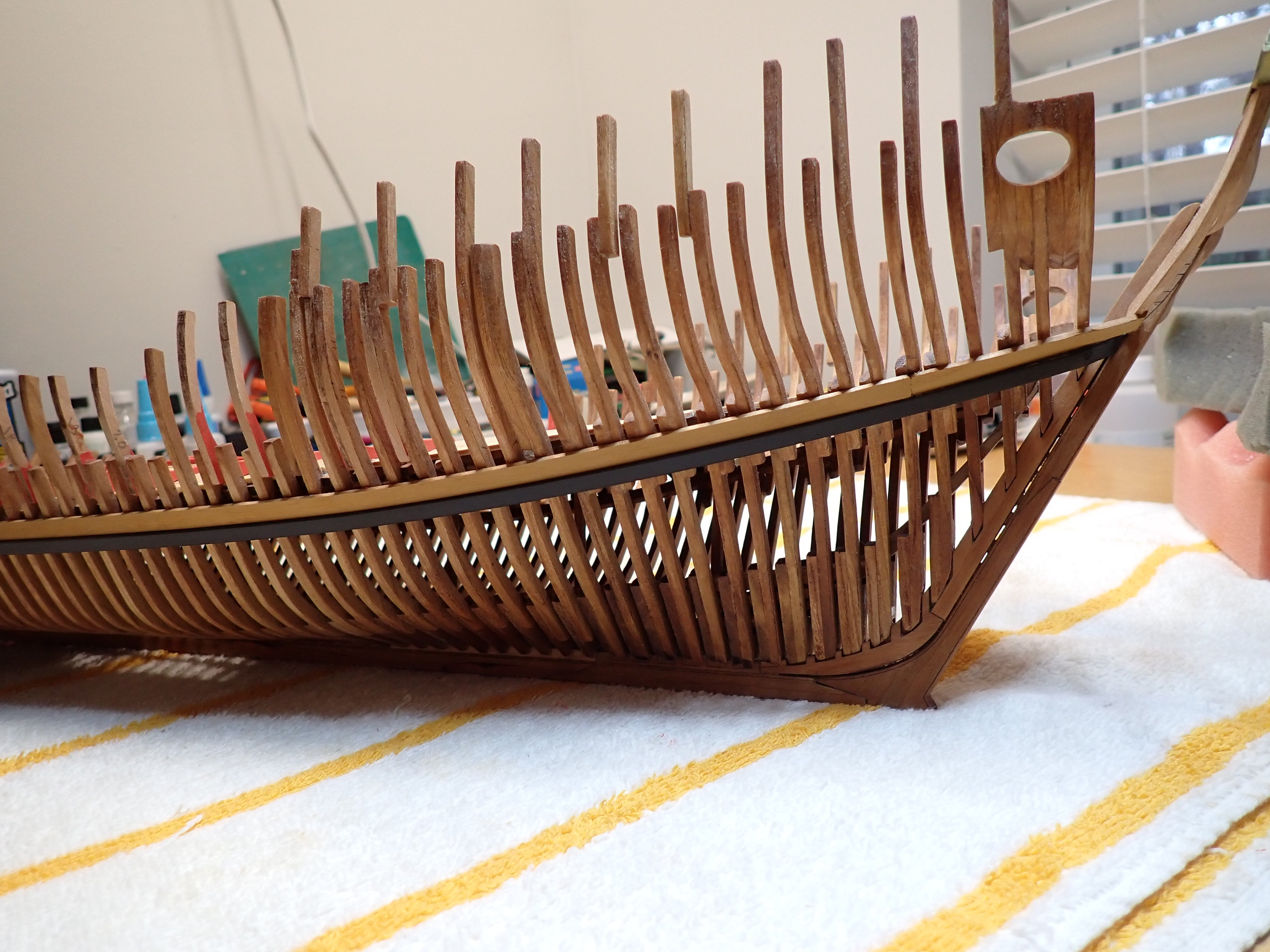
Now that the cat is out of the bag, I have been able to place the small frames around the gun ports. A picture from the instructions, for reminder:
I only did one side first.

And also started finalizing the fairing of the outside of the hull. Most of the heavy work was done when preparing the frames, so it is relatively easy, although very delicate because of the dryness of the wood cooked by the laser cutter.

All these small frames will be partially covered by the gun decks.
Et voila where we stand today. Now to work on the other side.
I strongly recommend to not install the lids in the middle of the deck as this opening is very valuable to hold the model. So, don't follow the instructions....
Yves
- vossiewulf, KARAVOKIRIS, gjdale and 17 others
-
20


Le Chebec by Yvesvidal - CAF Model - 1/48
in - Kit build logs for subjects built from 1751 - 1800
Posted
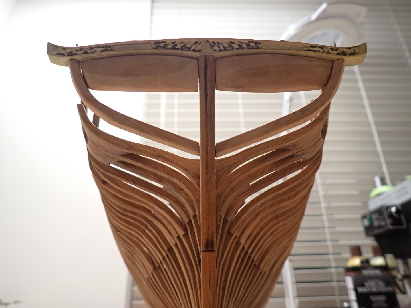
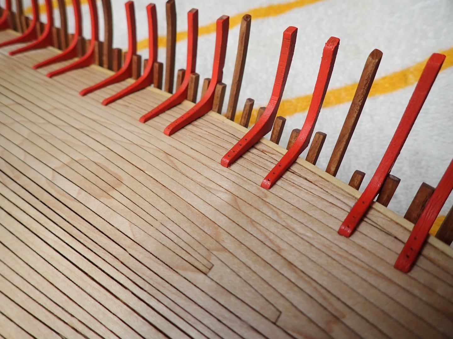
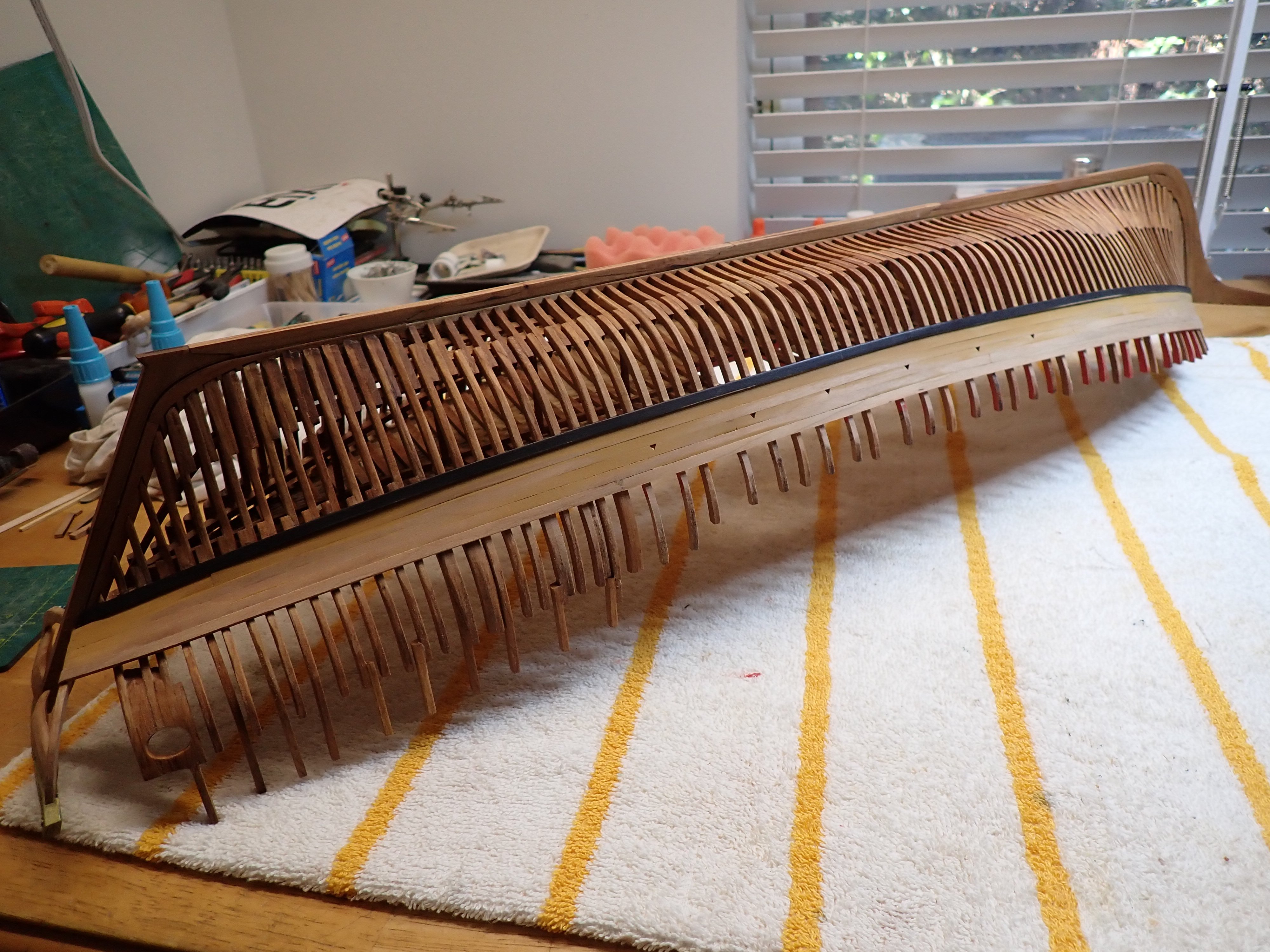
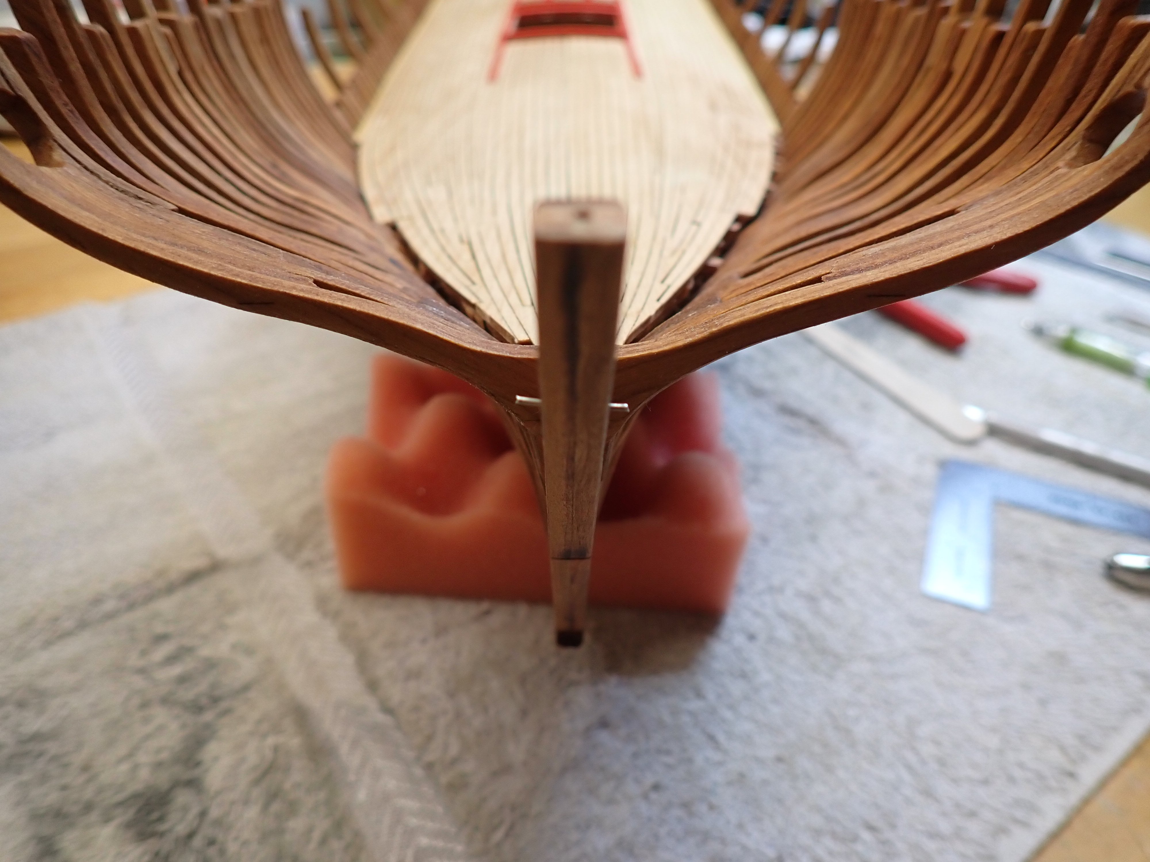
A quick improvement over the kit, that I would recommend dearly: Nail (for real), the gun deck supports. I used again nickel silver nails made with electronic component pins.
Add at the stern and the bow some re-reinforcements for the end of the gun deck planking:
With these improvements behind us, we can now start the planking, properly speaking. First plank goes against the frames (at least that is the way I am approaching it):
Then installation of the grates and tons of precise cuts.....
Yves