HOLIDAY DONATION DRIVE - SUPPORT MSW - DO YOUR PART TO KEEP THIS GREAT FORUM GOING! (Only 13 donations so far - C'mon guys!)
×


dvm27
-
Posts
2,457 -
Joined
-
Last visited
Content Type
Profiles
Forums
Gallery
Events
Everything posted by dvm27
-
 Lovely work Rusty. Sorry you were unable to attend our workshop and hope you make a quick recovery.
- 642 replies
-
- 3
-

-
- winchelsea
- Syren Ship Model Company
- (and 1 more)
-
NAIAD 1797 by Bitao - 1:60
dvm27 replied to Bitao's topic in - Build logs for subjects built 1751 - 1800
I have never seen deadeyes made in the way you have Bitao. Drilling the holes in the square stock before turning the deadeyes to their final diameter solves several problems inherent in making them. Not only does it remove the need to make a special jig to drill the holes after turning the stock on the lathe but it also insures that the holes are correctly positioned along the equator of the deadeye. As I note Ed made them in the traditional way in his books I assume you have reinvented the wheel, applying the logic you display elsewhere in your construction. Brilliant!- 371 replies
-
- 12
-
-
I do not bevel any of my frames until after they are installed and supported with fillers (which are later unglued with alcohol). During the beveling process the aft outer edge of the frame is reduced to Line 1. Line 2 represents the inside aft edge of the frame and chock after beveling. If the chocked joint does not receive a bevel the aft edge of the frame could break into it later. So the chocked joint must be beveled to prevent this. I do this on my mill but it can be readily accomplished by using a chisel.
-
Don't know if it helps but all swivels on my Speedwell have the muzzle at 4' above the deck as well Toni. Looks right.
-
Excellent, Mike! We were all horrified by your uncharacteristic 1/16" error. We'll sleep soundly tonight knowing that perfection has been restored.
- 607 replies
-
- 6
-

-
-
- winchelsea
- Syren Ship Model Company
- (and 1 more)
-
Not at all! After the workshop Chuck will be having a fire sale due to decreased rope sales.
- 345 replies
-
- 12
-
-
-
All rope is from Syren Ship Model Company. I have made rope but theirs is the best around in my opinion.
-
The hull looks beautiful Kevin. On my current model I inserted the treenails dry into the holes with the stock in one hand and the flush nipper in the other. This makes quick work of inserting the treenails. After this I used a 50:50 white glue/water solution to paint over the holes. Once dry the hull was lightly sanded and that was it. I did not have a single treenail fall out using this method (which I also used on the deck). As you also use termite control and another finish that would additionally lock in the treenails.
-
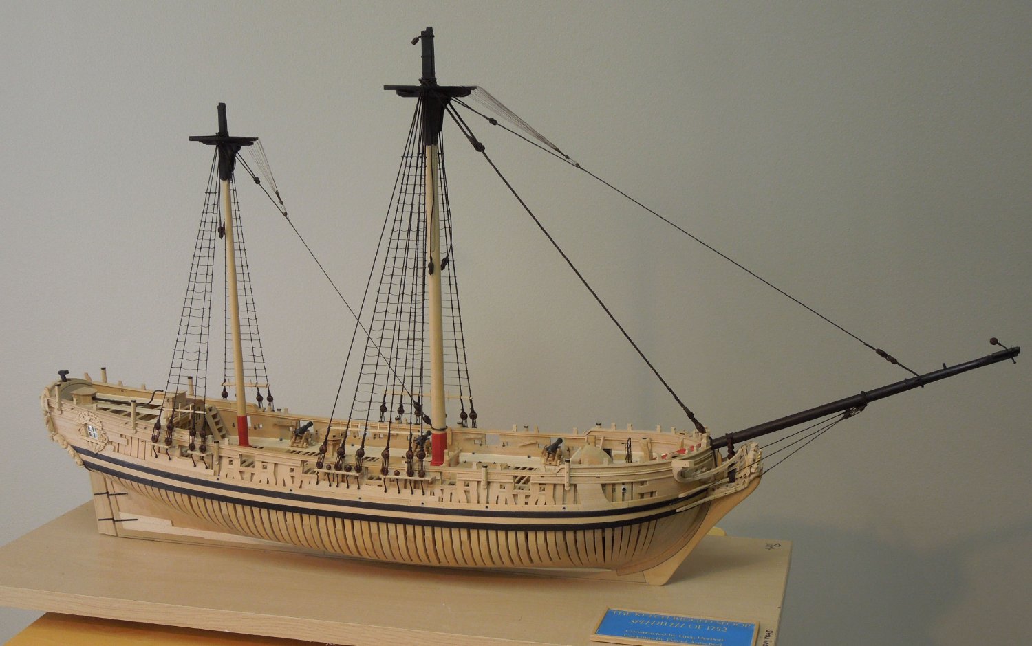
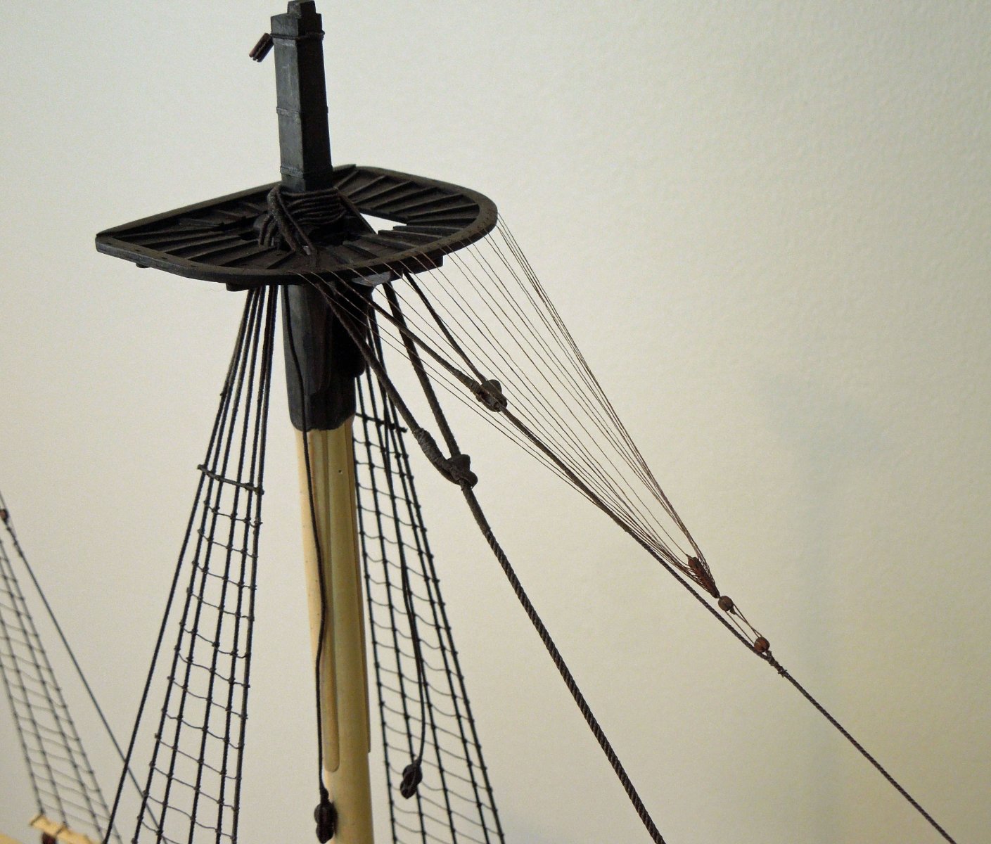
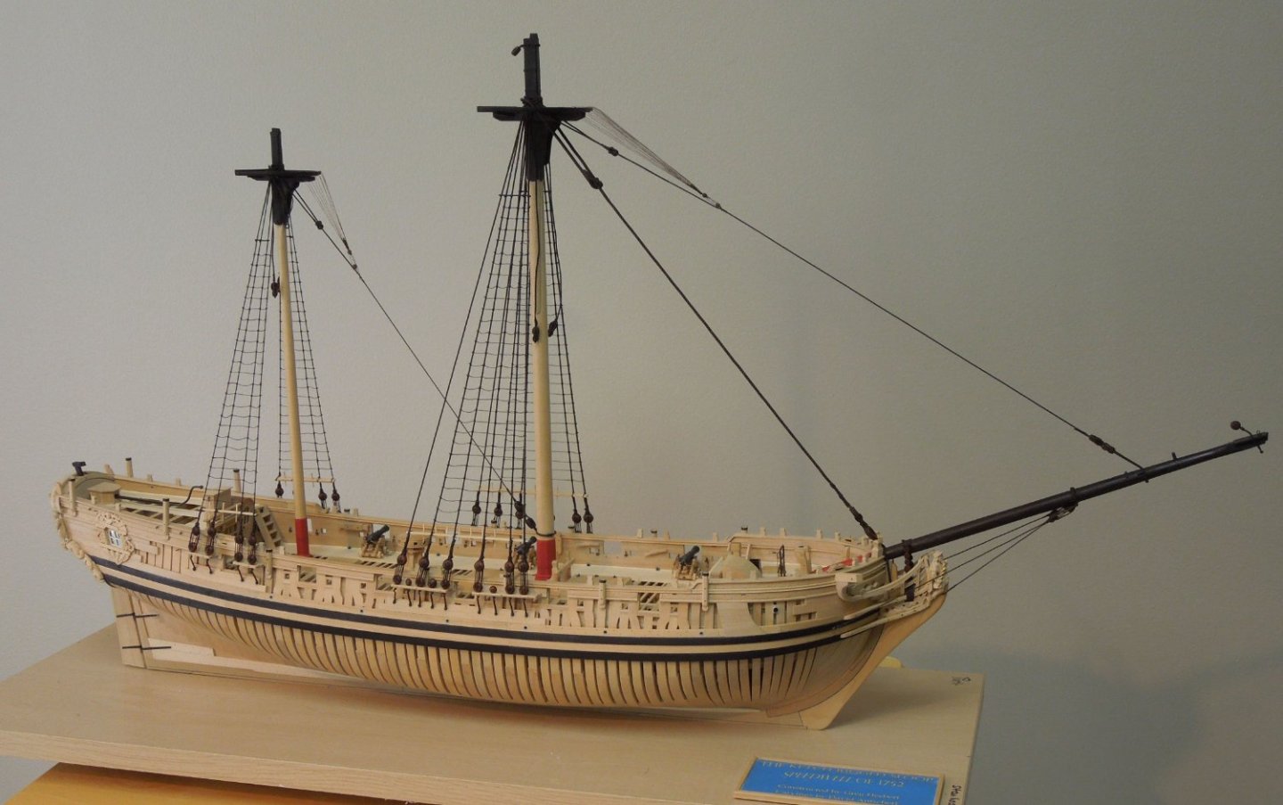
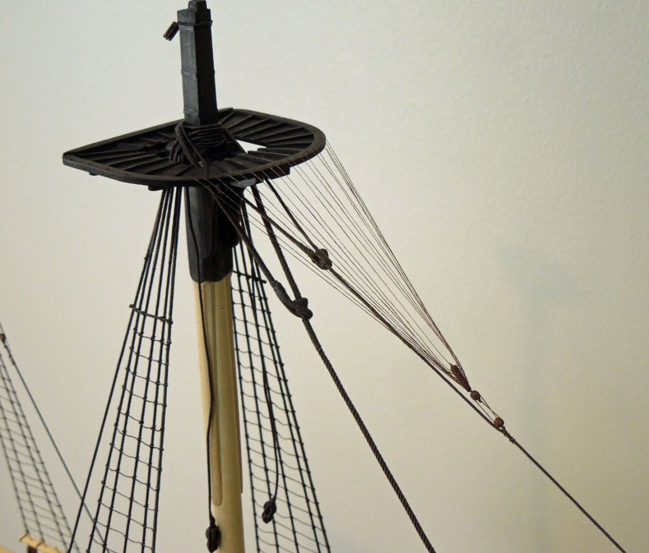
A small Speedwell update. The lower ratlines have been installed as well as the euphroe tackle and crowsfeet. On many models I see they appear oversize. At 1/4" scale though we should be able to approximate the 1" ratline and 3/4" crowsfeet diameters. For the ratlines I use Guterman polyester Mara 120 thread (dark brown). For the crowsfeet I used 6/0 Uni-Thread, dark brown. I tried 6-0 silk for this but it just kept fraying (such is the nature of silk). I must admit that making the euphroes with their numerous no. 78 drilled holes (there are nine in the main euphroe), setting up the euphroe tackle and rigging the crowsfeet was an exercise in patience (and frustration). I was so pleased with my first attempt until I realized that I had reverse rigged one hole and had to redo the whole thing. Onward and upward (literally)!
- 345 replies
-
- 54
-
-

-
Personal preference is key here Malcolm but to me a well tunneled deck or hull does not look like treenails were used until you get very, very close and then they are only faintly visible. It should be like "why did I go through all that effort as you can barely see them"? But they are there and you know it.
-
May I suggest you apply 1-2 layers of Tamiya tape to the keel, stem and sternpost before fairing in the treenails. An errant swipe of the sandpaper can create scratches that are difficult to remove later.
-
Those attending our Admiralty Models Workshop in two weeks will be amongst the first to see this collection in a private showing!
-
NAIAD 1797 by Bitao - 1:60
dvm27 replied to Bitao's topic in - Build logs for subjects built 1751 - 1800
Those volute scrolls would do a violin maker proud! -
Next time someone asks "what is museum quality" we should just refer him or her to this build!
-
The larger the needle gage the smaller the diameter. If you are trying to create a 1" scale treenail try using a 21 gage needle. The inner diameter is 0.5 mm. For a 3/4" treenail try a 22 gage needle. The medical or veterinary grade ones do dull quickly and I suspect it will take many needles to make the thousand(s) of treenails you need. You may wish to purchase stainless steel tubing such as https://www.grainger.com/category/pipe-hose-tube-fittings/tube-products/tubing-products/stainless-steel-tubing?attrs=Wall+Thickness|22+ga&filters=attrs and make them yourself. With the Byrnes drawplate I can make hundreds of bamboo treenails in ten minutes down to 0.018". With boxwood I can comfortably draw down to 0.020" without too much loss. Depends on the grain structure of juniper if you can draw it that fine.
-
I love whatever rendering process you are using. Looks very Van de Velde like.
-
Vandolay sold special 3/4" cutters for their treenail makers after I inquired about them. I still have them but quite honestly think the Byrnes treenail maker is the easiest and fastest way to make them. I start with bamboo skewers sold ib grocery stores.
-
Perfectly done lighting, looks very natural. Might be cool if you were to hollow out an area below the gratings and place a light there so it would provide the illusion of a lower deck.
-
Lovely work, Ben. Would it be possible the stitch both decals together and apply them as one to cover the seam?
- 399 replies
-
- 1
-
-
- winchelsea
- Syren Ship Model Company
- (and 1 more)
-
I've had nightmares about backing up a rig like that!
-
One of my favorite You Tubers The Art of Boat Building recently did a video on making a mast. He used many of the same techniques we taught in our Admiralty Models workshop on masting and sparring for making a tapered mast. Check out his video https://www.youtube.com/watch?v=KaWIIiv9zRg&ab_channel=TheArtofBoatBuilding. His next video was on building a half hull model and his lofting and building of the model should interest many of the modelers here. Bob is a true artist and craftsman:
-
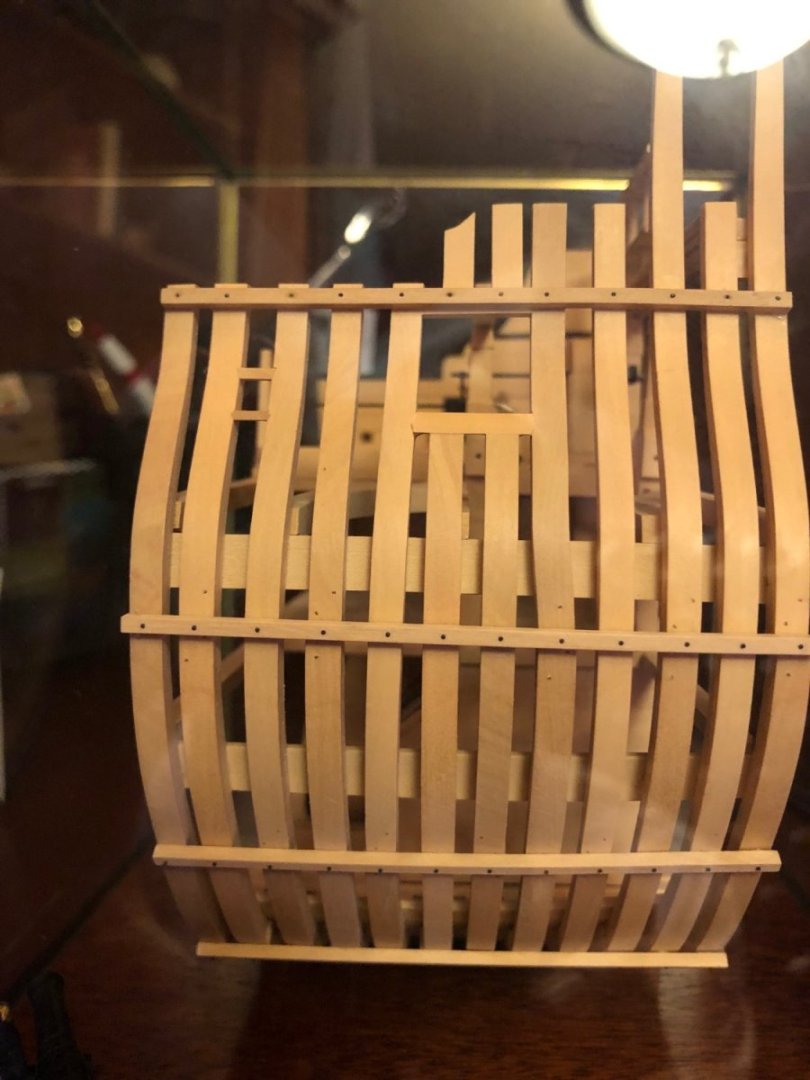
Been awhile since I made this frame but perhaps the photo will show better what I've done. I'm pretty sure I started with a wider toptimber and shaped it to fit the offset. It needs to be wide enough at the top to form the side of the port. Then shape downwards in a smooth arc to fay into the next futtock.
-
June 2022 Nautical Research Journal
dvm27 replied to Roger Pellett's topic in NAUTICAL RESEARCH GUILD - News & Information
Congrats to the publisher of this issue - it's fantastic!