HOLIDAY DONATION DRIVE - SUPPORT MSW - DO YOUR PART TO KEEP THIS GREAT FORUM GOING! (Only 20 donations so far - C'mon guys!)
×


dvm27
-
Posts
2,457 -
Joined
-
Last visited
Content Type
Profiles
Forums
Gallery
Events
Everything posted by dvm27
-
 Either one would work so long as the ports are correctly framed. But, I believe the right image ("sided") is the one I used as I included the widths on my working copy.
 -
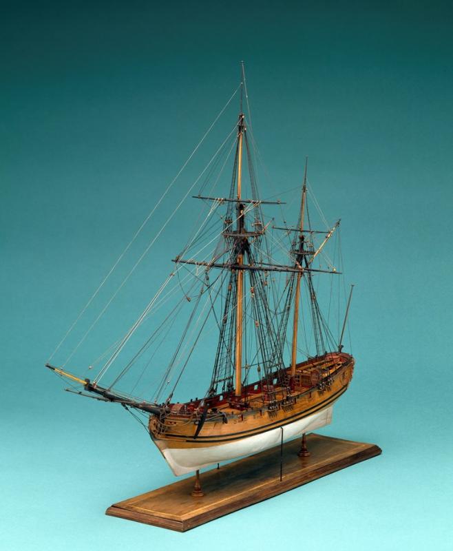
Speedwell will be a wonderful follow up project for those building Winchelsea. I'm about 2/3 finished rigging her and it's also a lot of fun, without all the repetition of a ship rigged three master. Chuck has chosen well - she is a beautiful little ship. For those not familiar with her there is a particularly fine model in the NMM on which our model was based. Here is a link to the photo. There is also are also superb McNarry and Reed models as well as a lovely bone model if you do an internet search. https://modelshipworld.com/uploads/monthly_07_2016/post-505-0-31402400-1468369675.jpg
-
Nice job Kevin. I've not seen silver soldering done where the solder was sweated on one piece first (like tinning in soft soldering). Also, that large metal nut you are using to secure one piece acts as a heat sink drawing heat away from the joint. That's why those ceramic pins you ordered work so well. I would start by making brass rings. The more you make the better the joints will be as you refine your technique. I agree with you that you can't accurately hang the pintle straps until the gudgeon straps are in place. I would hang the top and bottom pintles first then fill in the middle three.
-
ancre Le Gros Ventre by ChrisLBren - 1/36
dvm27 replied to ChrisLBren's topic in - Build logs for subjects built 1751 - 1800
Fantastic work Chris. Are you getting more time in the workshop these days? -
Swan-Class Sloop by Stuglo - FINISHED - 1:48
dvm27 replied to stuglo's topic in - Build logs for subjects built 1751 - 1800
Yes Druxey, my grandfather told me of such a thing, but few living people have actually experienced it😉 -
I made my own and they were fun to make. I suppose you could make them without a lathe but it would be a lot more work. But, if using a lathe, the order of operations is critical. As well you'll need a mill with a rotary table or drill press with a holding jig for the deadeye holes. Or, you could use CNC if you have the equipment https://modelshipworld.com/topic/19253-le-gros-ventre-by-marsalv-148-pof/page/15/#comments. If you have none of the above and need only a few then I would buy them from Syren as theirs are the best commercially available and pennies apiece. Otherwise the investment in equipment would be hundreds of dollars!
-
A simple jig will insure that the frames are level and parallel. Use a 1/8" plywood piece that's taller than the top timbers and wider than the widest frame. In the center mortise out a slot the width of the keel and height of the rising wood. Glue a couple of 45 degree pieces on the back to keep the jig at 90 degrees to the building board. If your jig is a very tight fit to the keel you can slide it up and down the keel to insure the frames are at the correct location. By marking a centerline on the jig you can pencil in the height of the top timbers and maximum height of breath of the frame to insure they're installed correctly.
-
Your steady rest is ingenious Johann!
-
Nice planking runs, Gary!
-
Like Chuck I have had the privilege of test driving Jim's new disk sander and echo everything that Chuck has written. As a scratch builder I find the disk sander amongst my most used power tools and the new version is smaller, quieter and in every way the equal of the larger version. But it has the added advantages of a reversable motor and variable speed. There are many times where sanding a complex piece on the left side just makes things a whole bunch easier. As well the smaller disk is not a problem as how often does one use the full disk for sanding at one time anyway? Of course I'll keep both of my Byrne's disk sanders on the workbench - with different grits to speed up things. Hat's off to Jim for building a better mousetrap. Maybe now he'll consider a oscillating spindle sander for the workshop.
-
Lovely head work, Ben. This experience should come in handy when it's time to do those Pegasus head structures.
- 399 replies
-
- 3
-

-
- winchelsea
- Syren Ship Model Company
- (and 1 more)
-
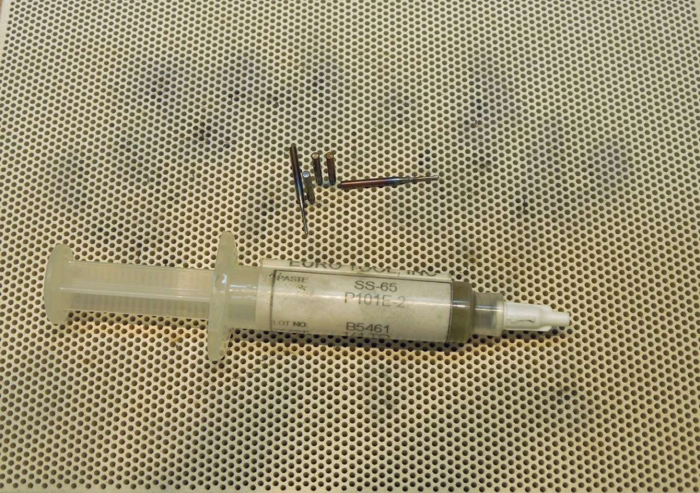
To hold objects in place for silver soldering I use the steel pins sold by Euro-Tools https://www.eurotool.com/soldering-tools-and-supplies_c_320.html. In order for a silver soldered joint to be successful there must be contact between the two pieces. Once I switched to their medium silver solder paste (which has flux in it) my silver soldering success went from a very low percentage to almost 100%. Before that I had problems with the small solder chips flying off as soon as the torch hit them.
-
Best of luck Bob!
-
Congratulations on the end of a wonderful journey Chuck! Didn't even take you the full two weeks to finish her up. I'll bet you're already in the workshop catching up on orders.
- 1,784 replies
-
- 6
-
-
- winchelsea
- Syren Ship Model Company
- (and 1 more)
-
We all know about the major sea battles but I believe I read somewhere that most of these vessels spent the majority of their careers without engaging in active battles. Beautiful work Glenn!
- 840 replies
-
- 5
-
-
- winchelsea
- Syren Ship Model Company
- (and 1 more)
-
Very nice job turning in those deadeyes and clove hitching the ratlines!
- 708 replies
-
- 1
-
-
- victory
- constructo
- (and 1 more)
-
I hear they're pretty good, Kurt. Mary has good taste. I tried unsuccessfully to get Steeles Masting & Rigging book. For $5 it's the bargain of the century!
-
Was wondering how you were going to handle this difficult area. it's like modeling a wave breaking on both sides.
- 1,784 replies
-
- 6
-
-
- winchelsea
- Syren Ship Model Company
- (and 1 more)
-
Brig Le FAVORI 1806 by KORTES - 1:55
dvm27 replied to KORTES's topic in - Build logs for subjects built 1801 - 1850
I beg to differ with you Kortes - there is plenty to show. Your meticulous lining out for the treenails and their placement is flawless. I'm guessing you'll need to touch up those wales after sanding the hull. -
That's a beautiful model Toni. I especially admire the fact that you have cast all the iron work yourself despite the presence of perfectly respectable items in the market place. Perhaps one day you'll come back and rig her when the mood strikes.
-
Congratulations on completing video #100 in your Swan series! No one can complain that there is a lack of information available for building a Swan class model.
-
NAIAD 1797 by Bitao - 1:60
dvm27 replied to Bitao's topic in - Build logs for subjects built 1751 - 1800
I'm not quite sure how Bitao did it but I used the rotary table in my mill. I don't have DRO and just basically tinkered with the setup until it was right but it wasn't a big deal. I assume Bitao uses a round file to form the groove in the middle and either a form tool or file to shape the exposed side of the deadeye. The deadeye is pulled of, reversed and inserted onto the holes so the opposite side can be shaped. -
I wish you could see the smile on my face Giampiero! You should slip a sleeping figure into one of the hammocks (out of site) for some future boroscope examiner to find.
-
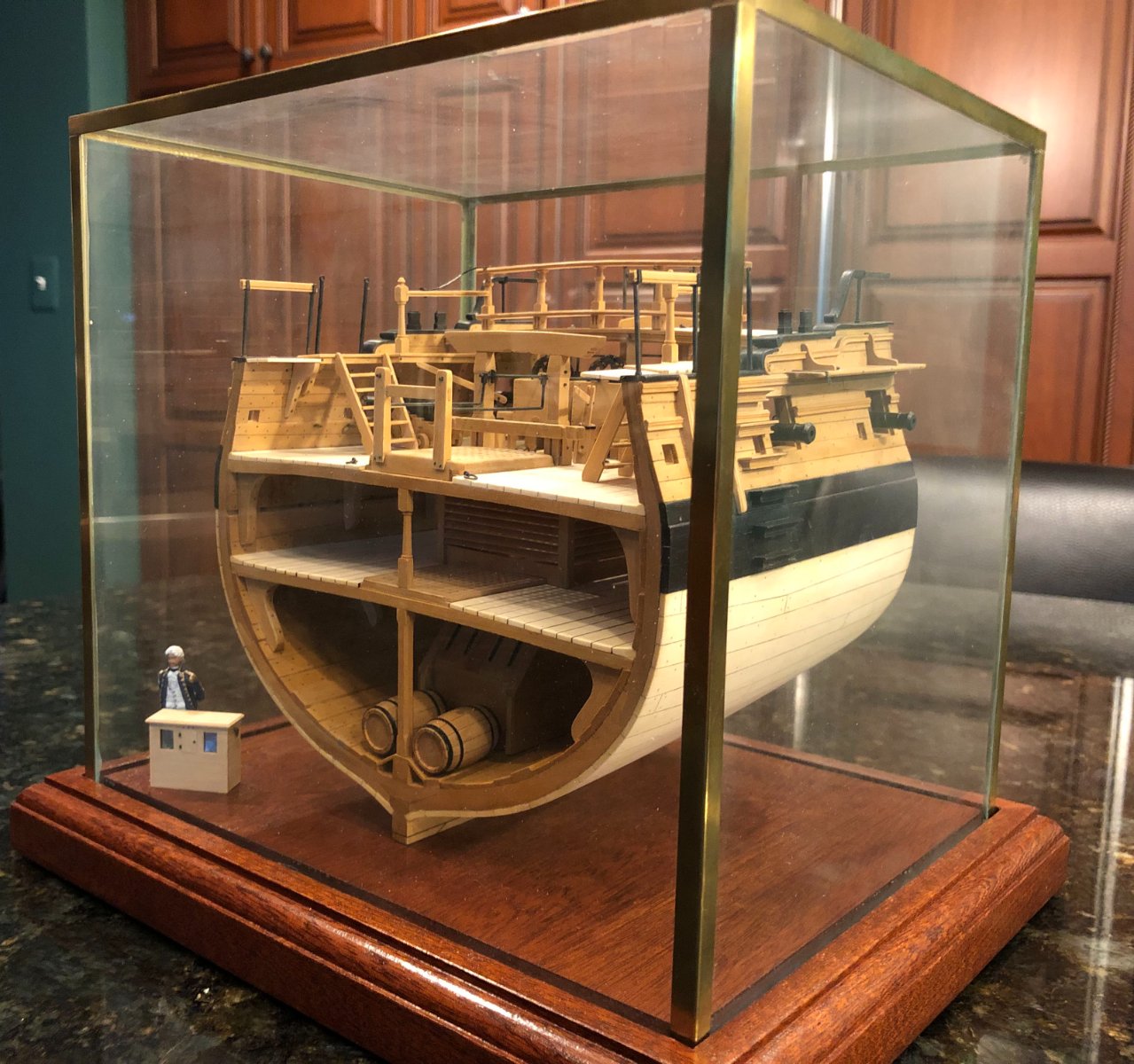
That's a very respectable frame for a new scratch builder John. Others have made excellent comments above and I agree with all of them. Do no fair the frames to the bevel lines. I do no pre-beveling on my plank on frame models. If you do so, leave at least 1/16" extra to account for the inevitable errors that occur when installing the frames. As well, use a digital caliper to make sure all frames are to speck with regards to thickness. Cumulative error is always waiting to get you! If you like tools invest in an oscillating spindle sander. It is the best way I know to shape the inside of the frame. You don't need the model with the angled table. Consider building a cross-section to get frame fundamentals down. Below is a photo of my swan class cross-section Pegasus. It's a great way get some of the basics of scratch building down.