
HOLIDAY DONATION DRIVE - SUPPORT MSW - DO YOUR PART TO KEEP THIS GREAT FORUM GOING! (Only 20 donations so far - C'mon guys!)
×


dvm27
-
Posts
2,457 -
Joined
-
Last visited
Content Type
Profiles
Forums
Gallery
Events
Everything posted by dvm27
-

Echo by davec - FINISHED - cross-section
dvm27 replied to davec's topic in - Build logs for subjects built 1751 - 1800
That looks terrific, David! Ebony is fine for a cross section like this as there not too much of it nor are there any major bends to do. I used it on my Pegasus cross section and it really is a beautiful wood. Agree with you that the model is easiest planked while not mounted. Fits nicely in your lap during the process. You'll be delighted to plank her in only a day or so. Its one of the reasons I chose this section. Best wishes for the New Year! -
Great recovery,Ben. Druxeys suggestion of gluing the spacer to one face only makes a lot of sense. Or, just cut and fit them without glue See what sort of gaps develop over the coming months.
-
Pandora by marsalv - FINISHED - 1:52
dvm27 replied to marsalv's topic in - Build logs for subjects built 1751 - 1800
Wonderful, Marsalv! Based on museum pieces I've seen she is exactly the style and look of contemporary figureheads. I wonder if it was a point of pride for opposing forces to blast the opposing ship's figurehead during battle? -
Lovely work, Chuck! Clove hitches are definitely the way to go, although you should point out to beginners that the ends are square knots (which you have also done extremely tidy on your model). Best wishes for a Happy New Year and look forward (hopefully) to seeing some progress on Winchelsia in 2017.
- 1,051 replies
-
- 6
-

-
- cheerful
- Syren Ship Model Company
- (and 1 more)
-
Just checked my Hannah which was rigged over 15 years ago. I used a combination of CA and Liquitex Acrylic Matte Medium (as suggested by Harold Hahn). I can't tell which lines were secured with which and they are all in excellent shape. That said, I recall the CA did stiffen the line a bit more than I wanted and made it difficult to form a graceful droop. No such issue with the matte medium, which also allowed for some adjustment during its setting up.
-
Wise move, Ben. I had the same issue when trying to drill my hawse hawse in v.1. At least you have them properly located now and finish by hand. I had little success doing them the way David recommends in the book (adding them to each hawse timber before gluing them in place). That requires a level of precision above my pay grade! Looking forward to next years continued progress.
-
Another wonderful video, Kevin. Looks like adding those sill mortises after the frames are raised is working out for you. A very Happy and Healthy New Year to you and we are looking forward to next years videos.
-
ancre Le Fleuron by juzek - 1:27
dvm27 replied to juzek's topic in - Build logs for subjects built 1501 - 1750
Wonderful start. Looking forward to viewing this build. -
Well, I know one thing for sure. The metal work on this model will be outstanding!
- 162 replies
-
- 5
-
-
- dirty dozen
- fishing
- (and 2 more)
-
Nice recovery, Kevin. I suppose you were blessed/cursed with having the Thorn framing plan. Goes to show you that even thought the Swan vessels were a class within themselves with designated Admiralty specs, their builders still took liberties with regards to their actual construction (most likely based on their own apprenticeship). I'm pretty sure I recall David writing somewhere in TFFM that, in case of discrepencies, the plan for your individual vessel should be the ultimate source. With regard to creeping error you can always cheat an inch or two off either side as you approach the dead flat. You might want to construct the dead flat three-frame-assembly now and temporarily place it to help you figure out how the other frames will fill in. I found this very helpful. Your assistant Ollie is darned cute!
-
Your choice of ship modeling subjects certainly showcases your extraordinary carving talents, Ivan. I wonder if our readers are aware of the beautiful book published featuring your ship models or you website?
-
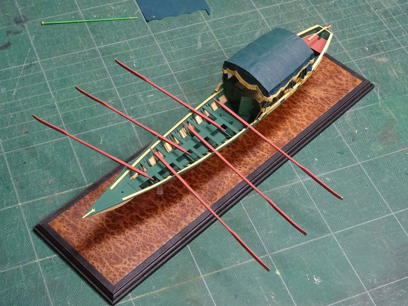
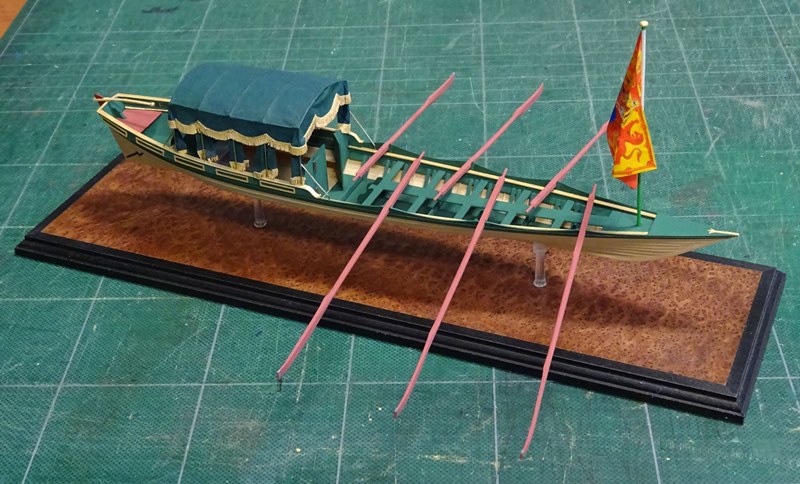
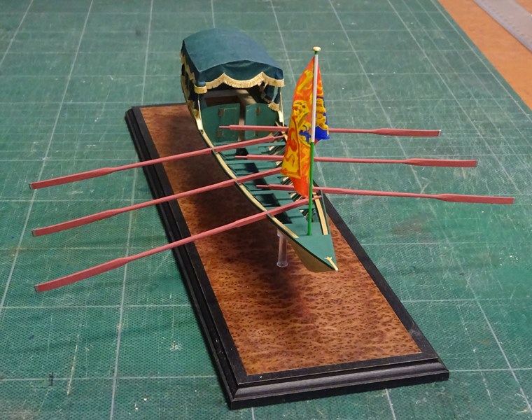
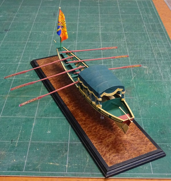
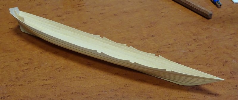
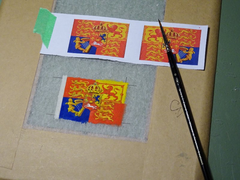
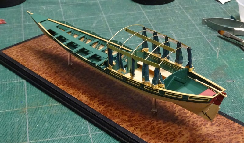
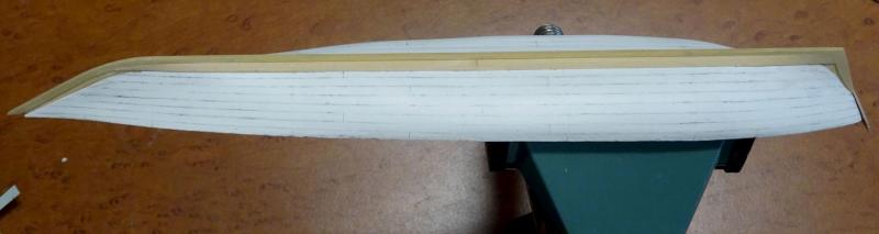
Below are some photos of a Royal Barge, 1823, built by David Antscherl. The techniques of construction are identical to those in his new book The Greenwich Hospital Barge of 1832. The clinker planking and delicate fabric covered awning are what drew me to her. Perhaps this belongs in the completed models section but I have added some construction photos because I thought many readers might be interested in them.

- 9 replies
-
- 27
-
-
- greenwich hospital barge
- royal barge
- (and 2 more)
-
Druxey's Hospital barge is truly a wonder, especially when viewed in person. Its precision, coupled with its small size, makes for a beautiful presentation and heirloom. As someone who owns one of Druxey's barges I can tell you that I gaze at it daily, something I never do with my own models. It is rare for one of Druxey's models to be offered for sale as most are built as commissions. The Hospital barge is available for purchase. Being the subject model on which his new book is based will only increase its value over time. If you are interested please send a PM to Druxey.
- 641 replies
-
- 5
-
-
- greenwich hospital
- barge
- (and 1 more)
-
Those stamps are beautiful Alex. How did you add the dimples on the positive face? They are perfectly placed. Was this done by CNC?
-
I agree, Christian. The stern deadwood is more difficult and you have to match starboard and port sides prefectly, especially the positions of the steps. CNC would certainly make this easier!
-
Outstanding, Christian. Looks like you've left well in excess of 3" on those steps.I can't tell from your photograph but the aft deadwood above the bearding line should taper to 10" at the stern deadwood.See TFFM 1.23.
-
Great to see your progress, Glen. Ironic that you caught the Norovirus while working on your steamship. I imagine GI problems were a common concern on these vessels given the sanitary facilities. Love that you can design and create parts like the capstan in your workshop. I noticed that the chock mortises on the whelps are on one side only. Not that you see them after the rings are on but can you turn over and align laser cut pieces for a cut on the other side?
-
Beautifully done, William. It's certainly easier to do this on a flat surface vs. on the model. Are you going to add the balustrades? That should be challenging.
-
Your approach to the rising wood will help you immeasurably when it comes to raising the frames, Christian. Well done!
-
sharpening stones which are best for the price
dvm27 replied to John Allen's topic in Modeling tools and Workshop Equipment
Good advice above plus I'd recommmend the Veritas sharpening system with it's guides. For strait edged chisels you're guaranteed a perfect edge. -
HMS Naiad 1797 by albert - FINISHED - 1/48
dvm27 replied to albert's topic in - Build logs for subjects built 1751 - 1800
Clean, precise, unblemished workmanship. You're the total package Albert! -
I wish I had your skill and speed, Michael. You should be done the entire project in what...two weeks?
- 749 replies
-
- 4
-
-
- albertic
- ocean liner
- (and 2 more)
-
Pandora by marsalv - FINISHED - 1:52
dvm27 replied to marsalv's topic in - Build logs for subjects built 1751 - 1800
Love the technique Marsalv. I believe you're correct, Gary. He is freehand feeding the piece against the pin. The setup is like a router except upside down. -
Pandora by marsalv - FINISHED - 1:52
dvm27 replied to marsalv's topic in - Build logs for subjects built 1751 - 1800
Thanks for the explanation Marsalv. I assume you are using CNC to do this. I would think it would be quite difficult to freehand this.

