HOLIDAY DONATION DRIVE - SUPPORT MSW - DO YOUR PART TO KEEP THIS GREAT FORUM GOING! (89 donations so far out of 49,000 members - C'mon guys!)
×


Mike Y
-
Posts
1,557 -
Joined
-
Last visited
Content Type
Profiles
Forums
Gallery
Events
Everything posted by Mike Y
-
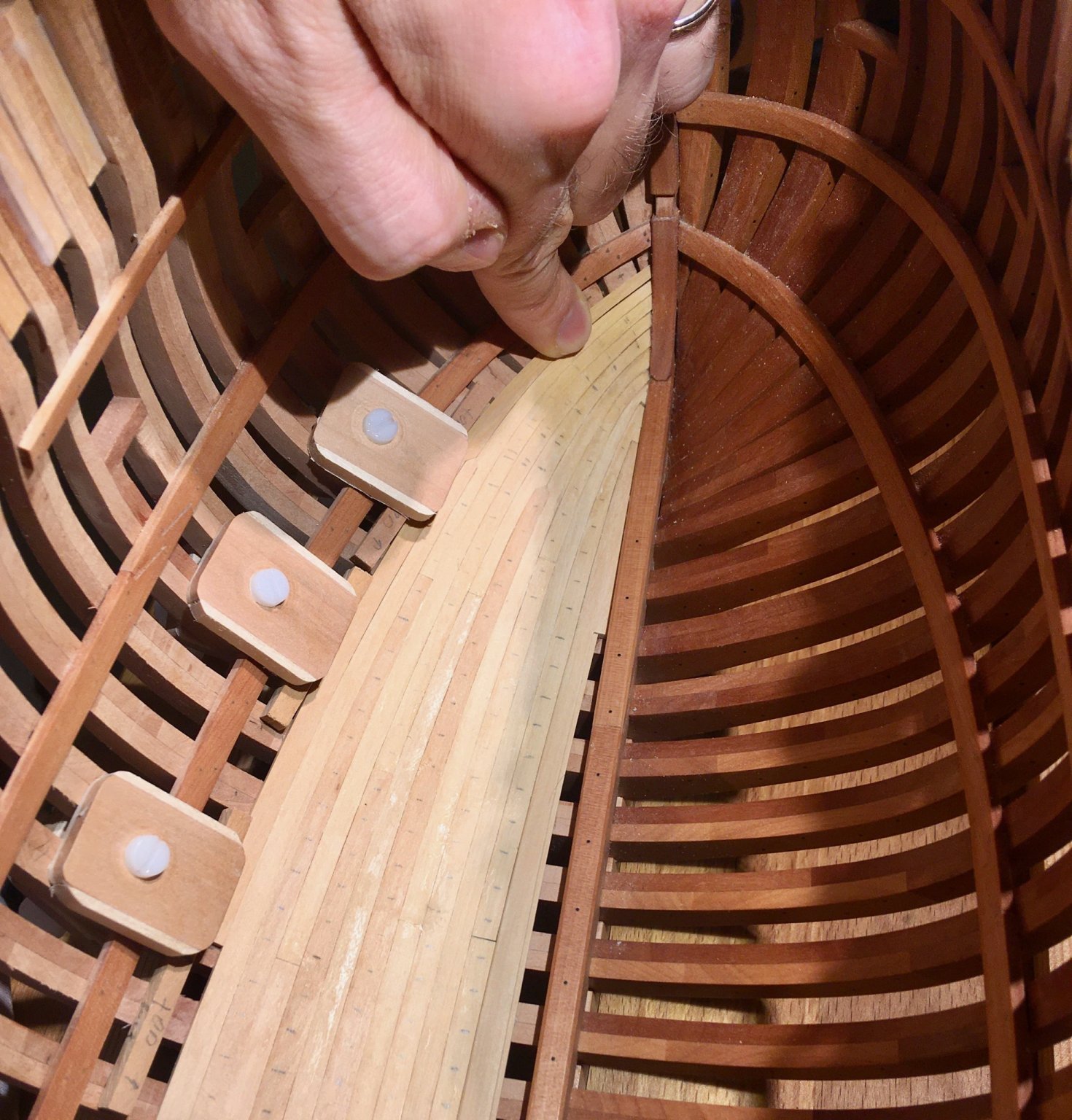
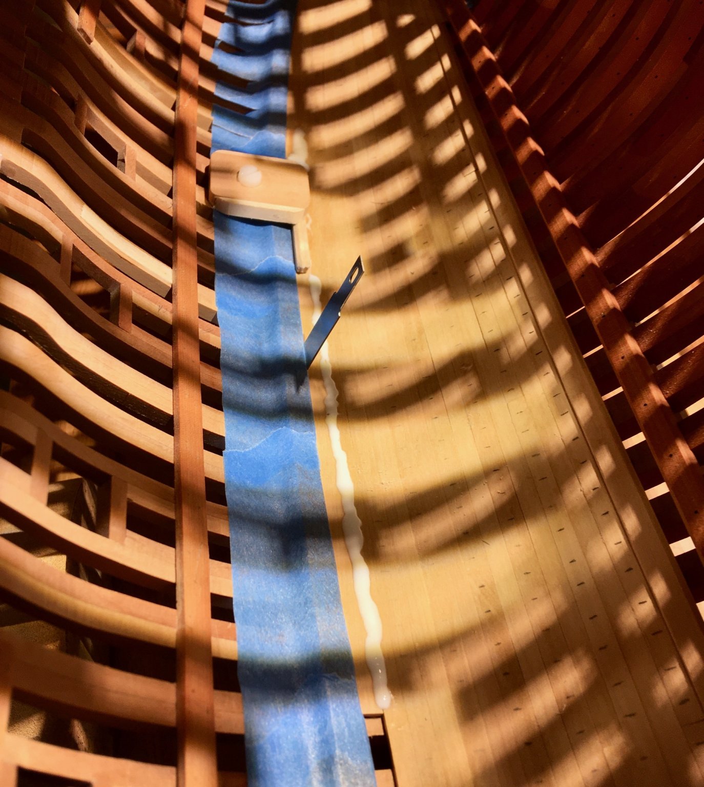
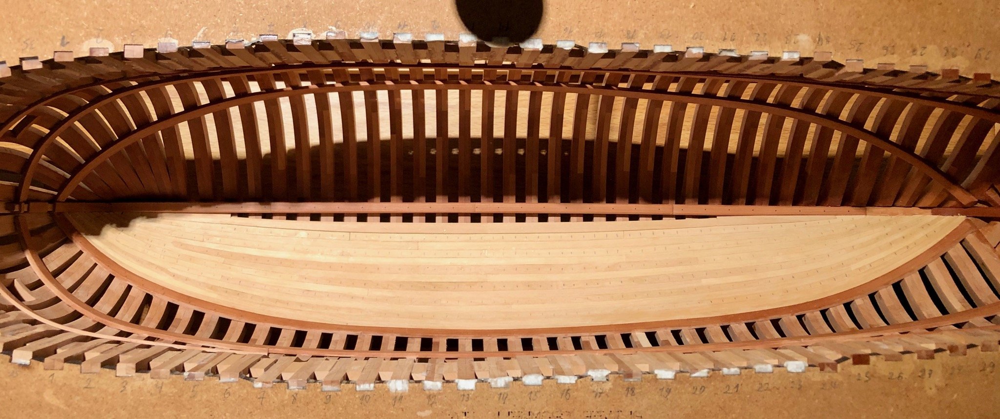
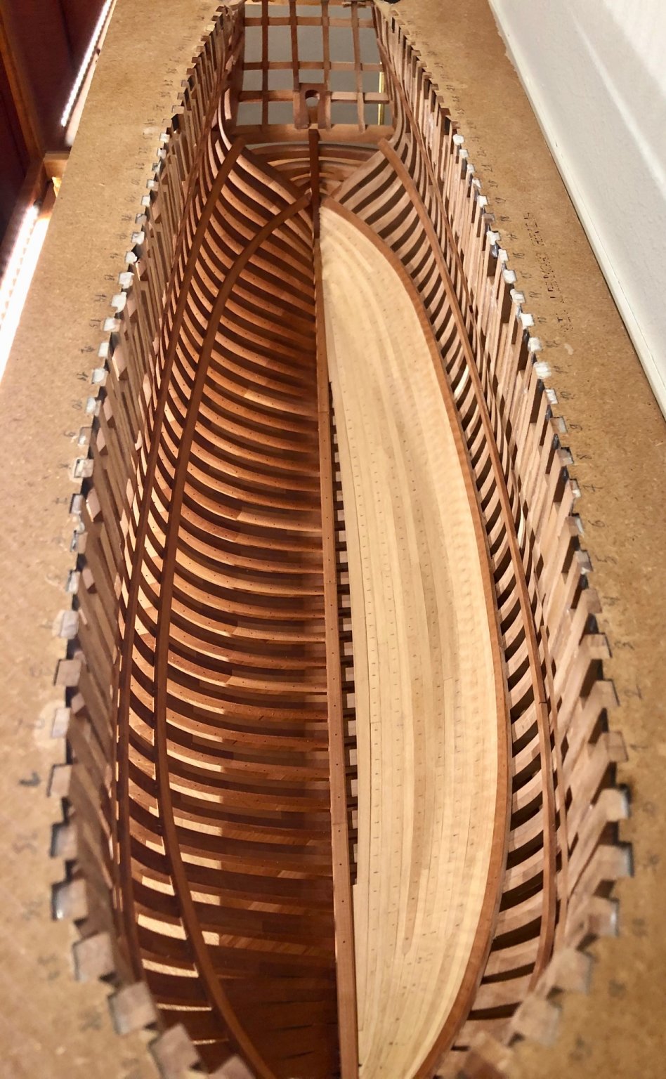
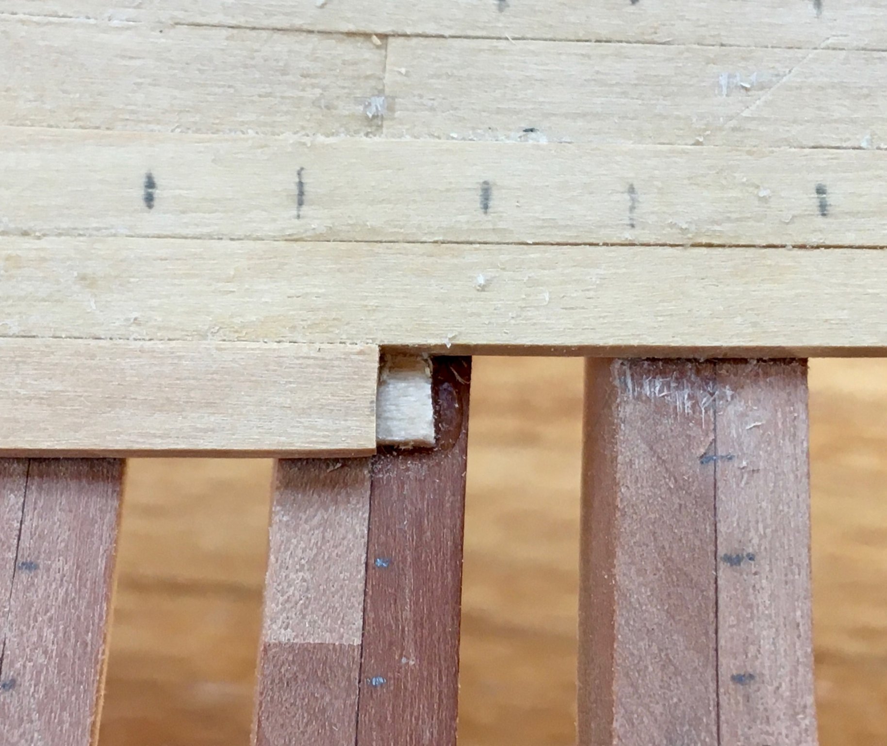
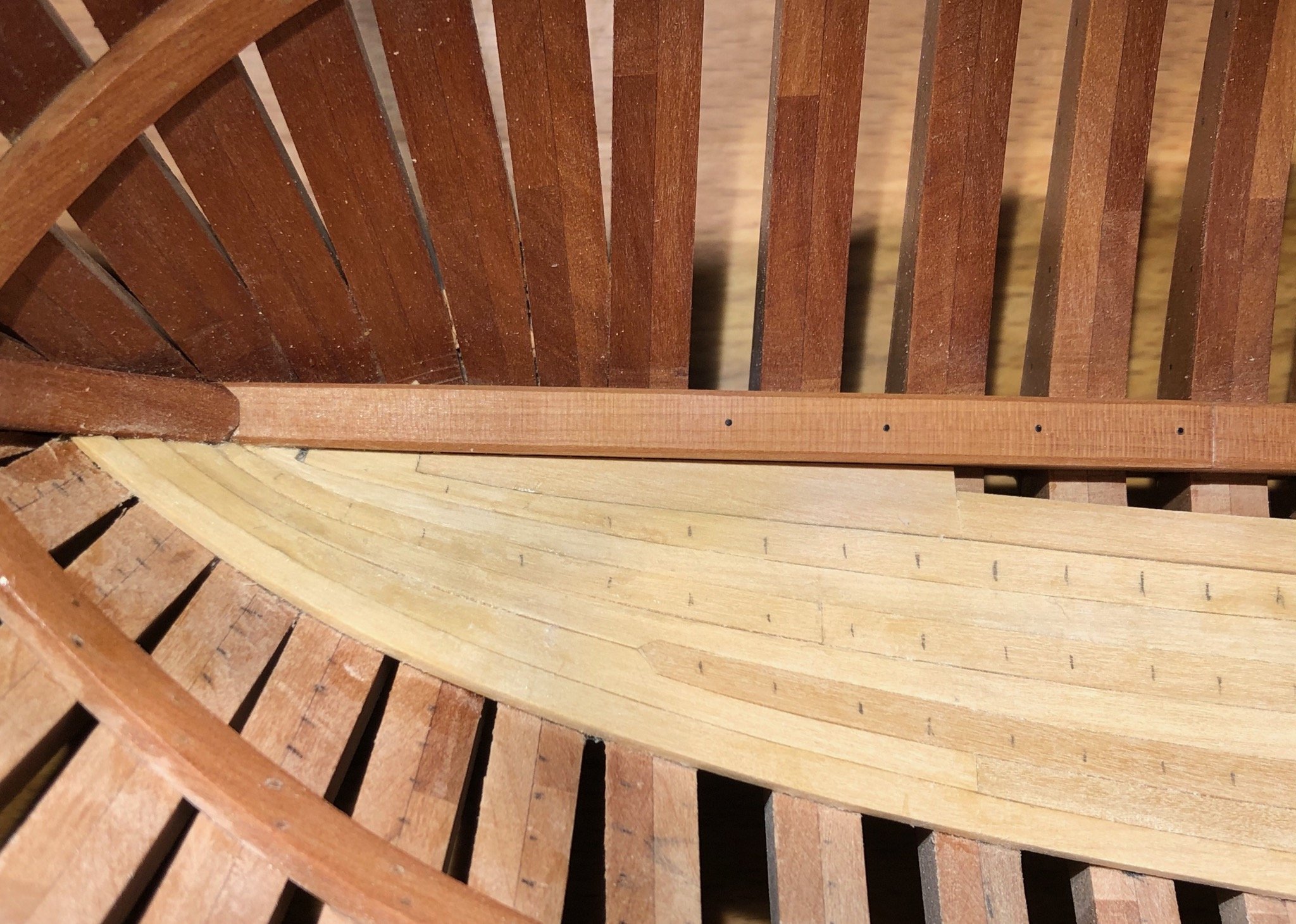
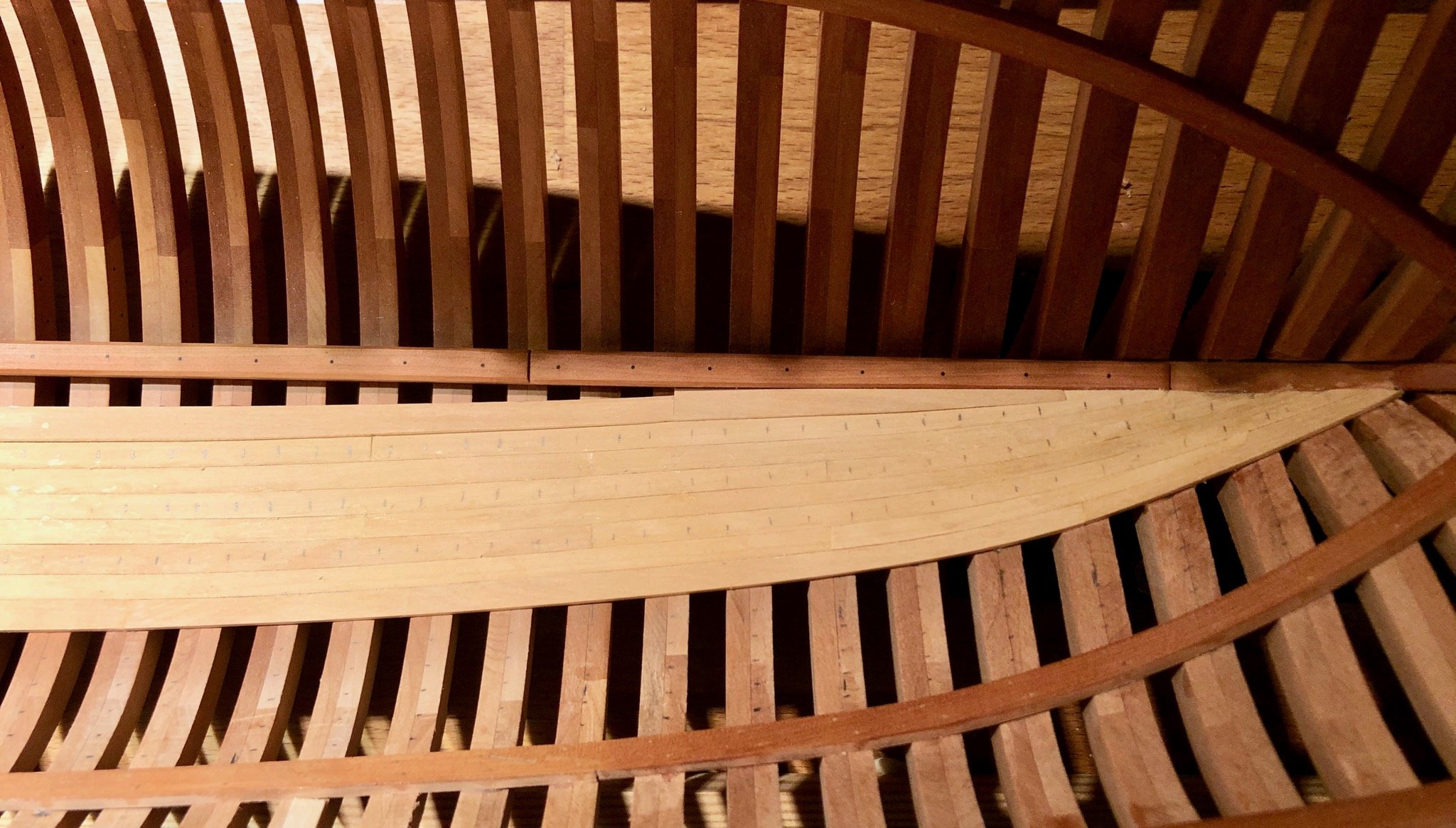
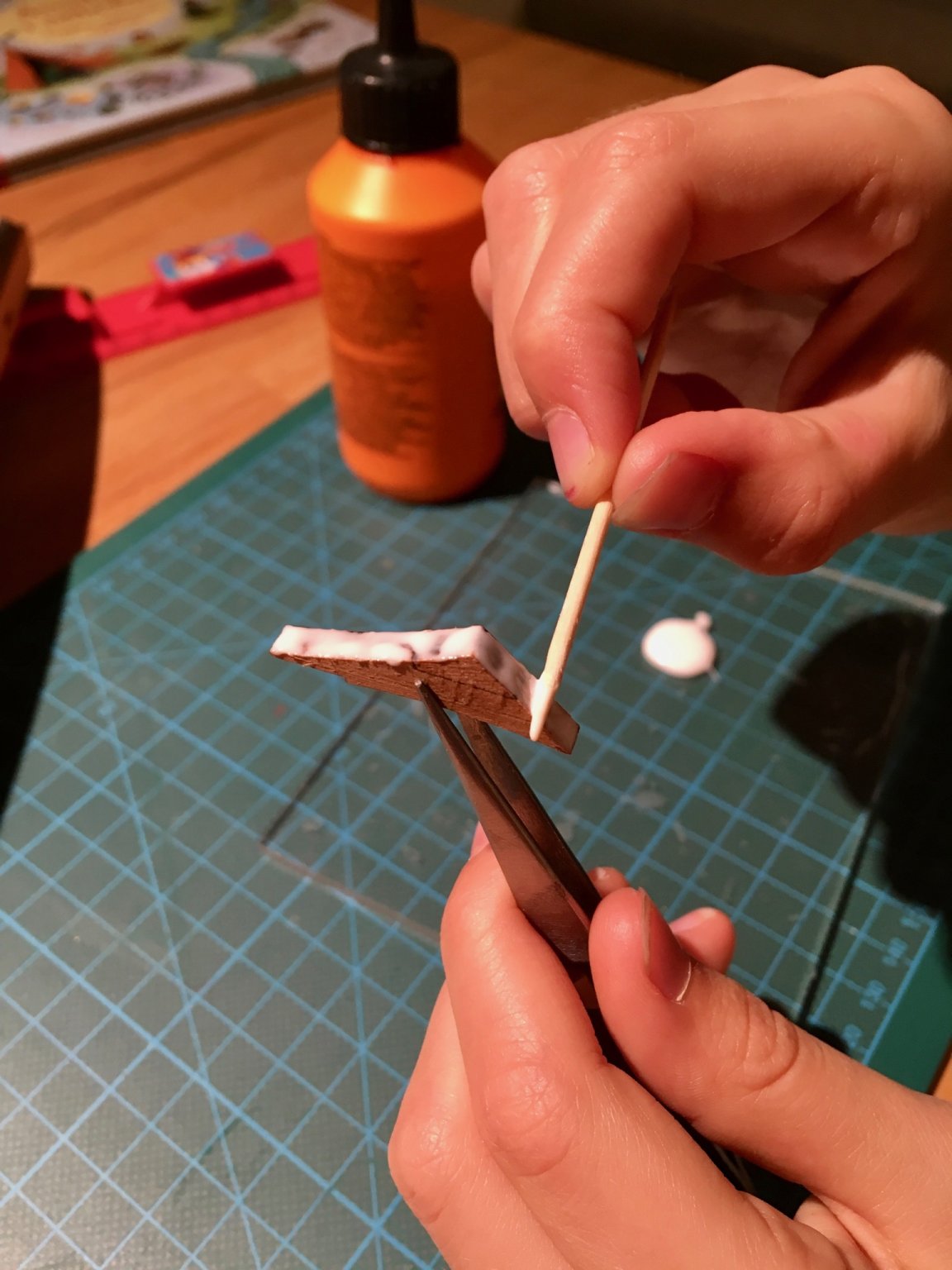
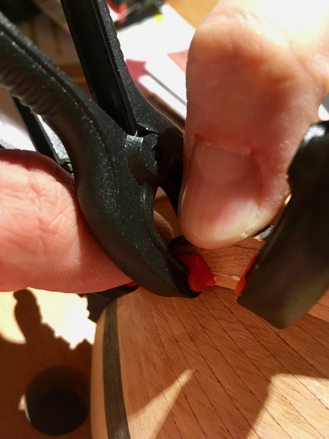
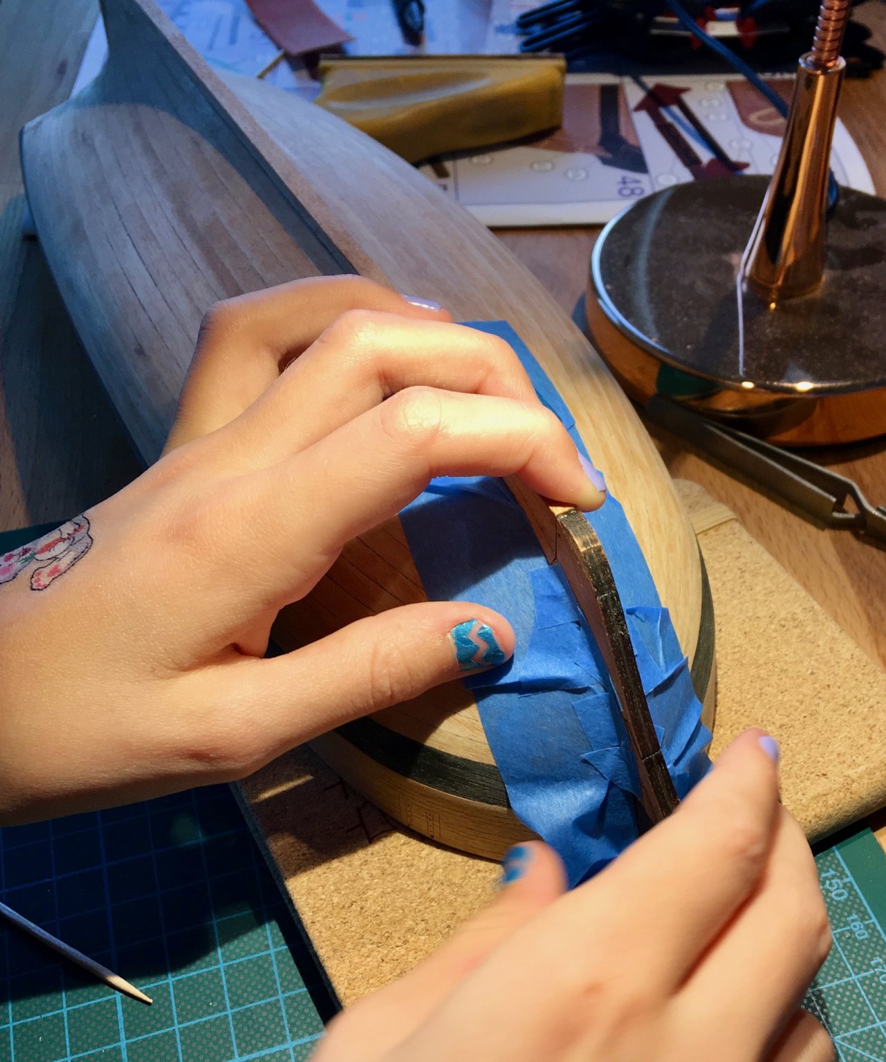
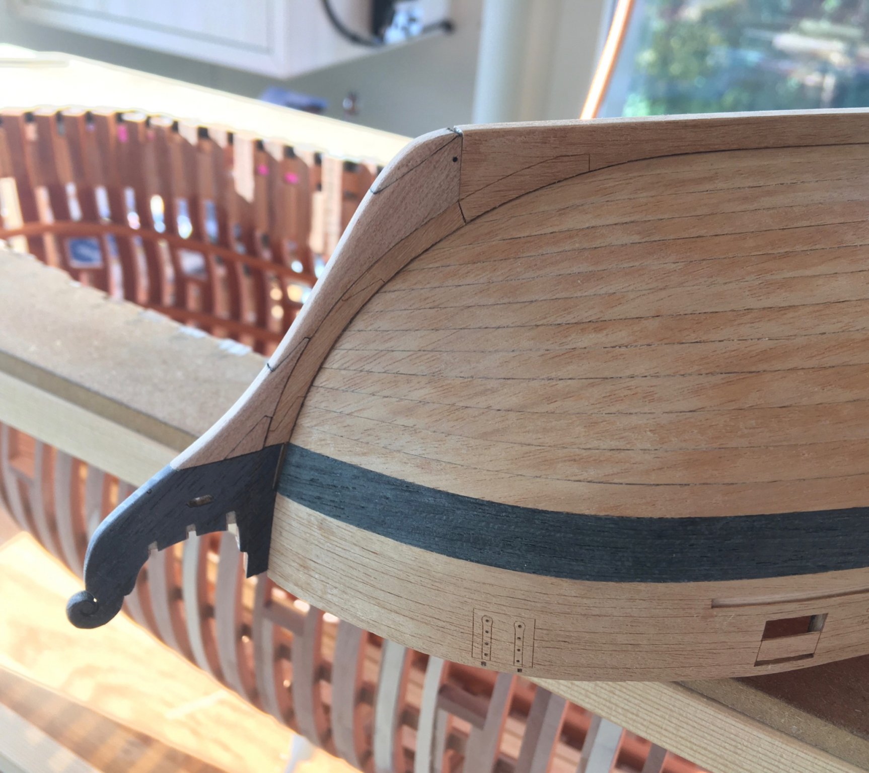
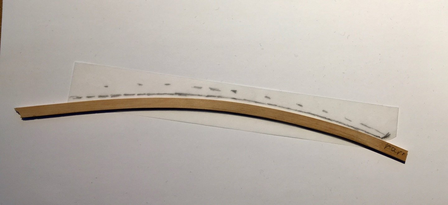
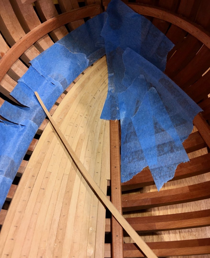
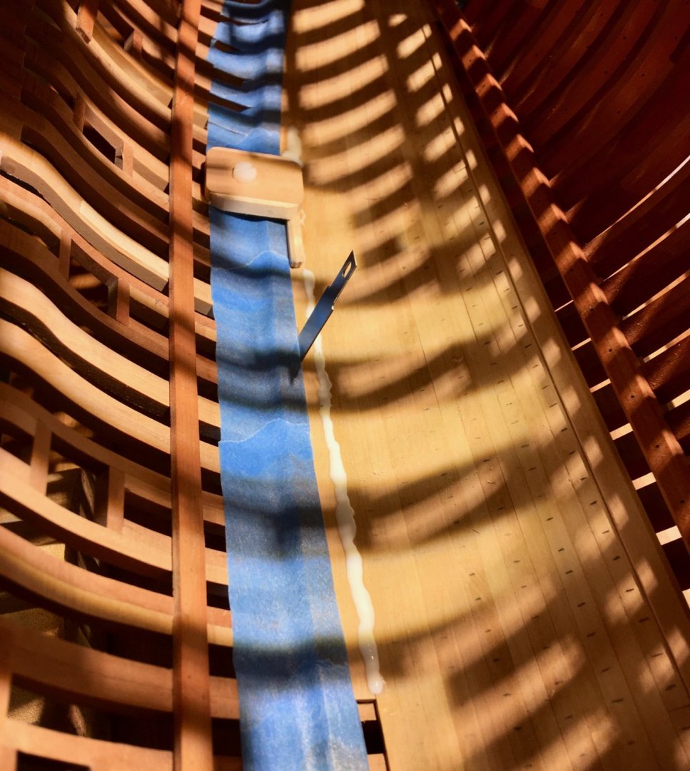
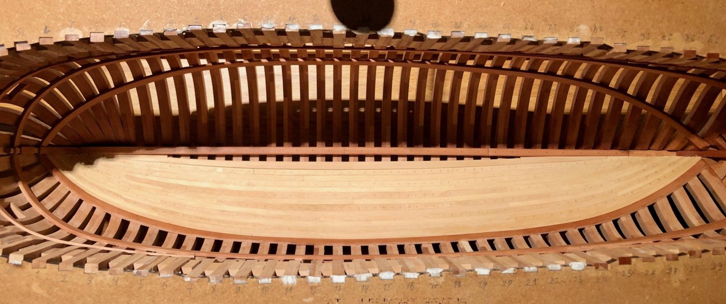
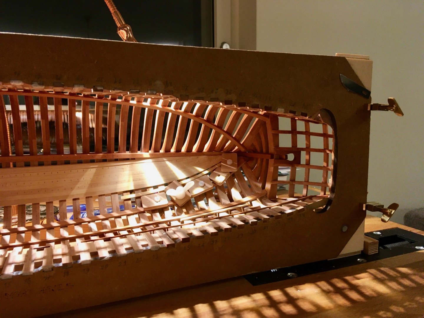
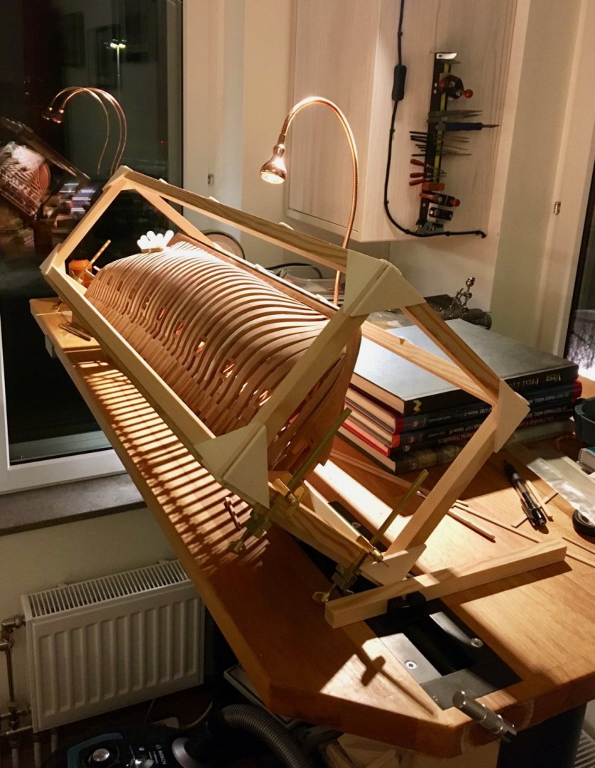
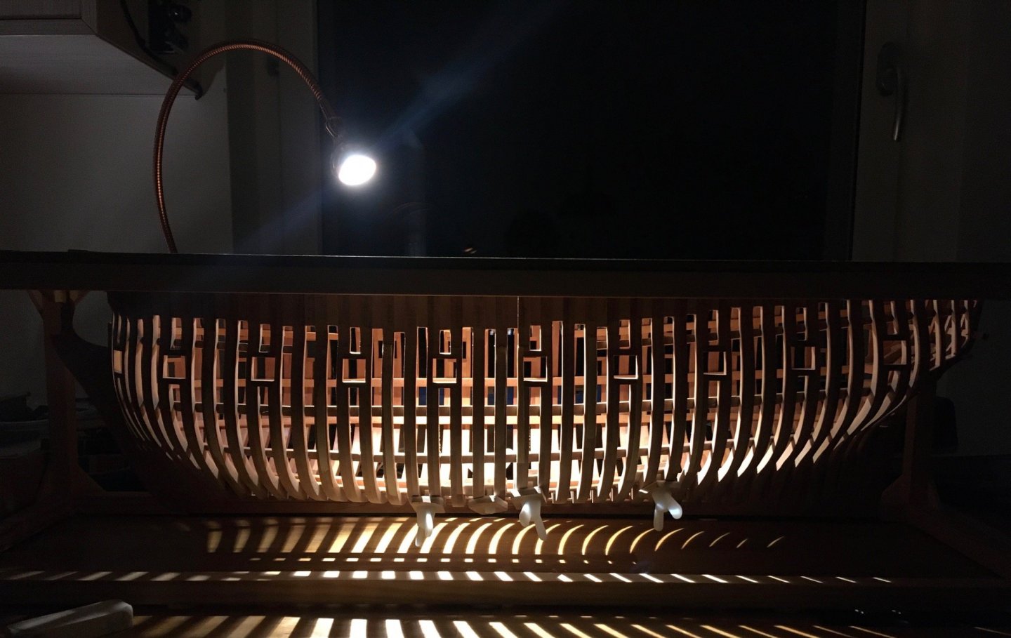
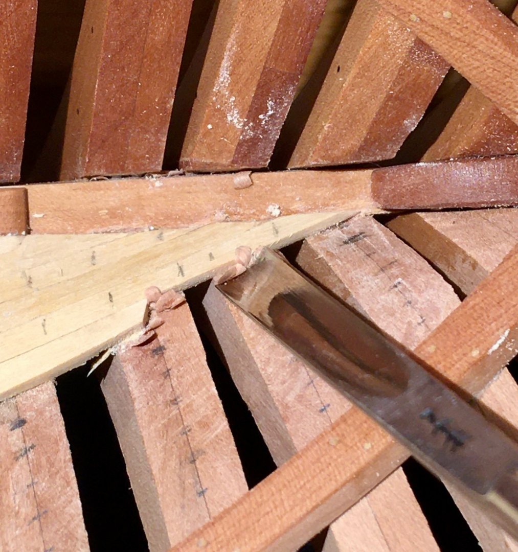
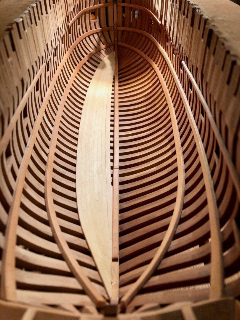
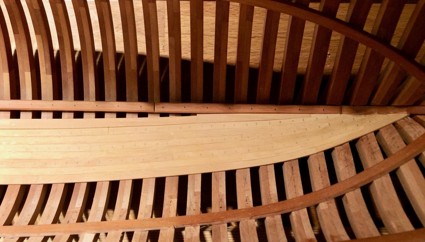
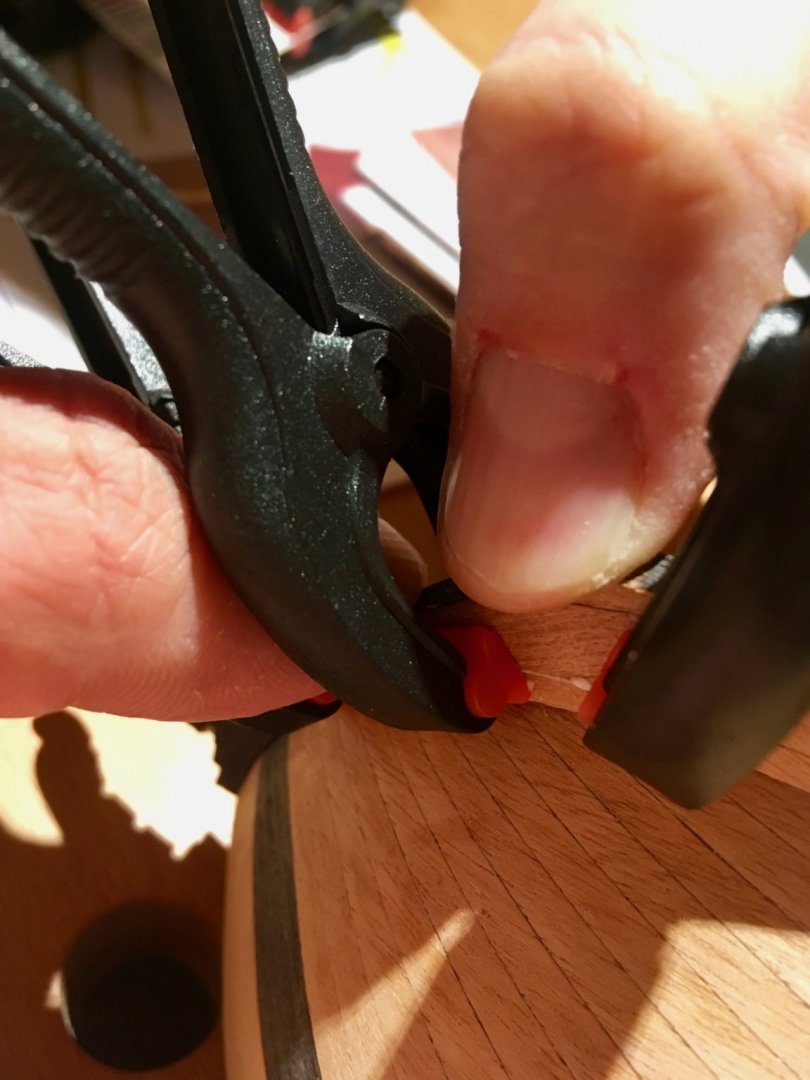
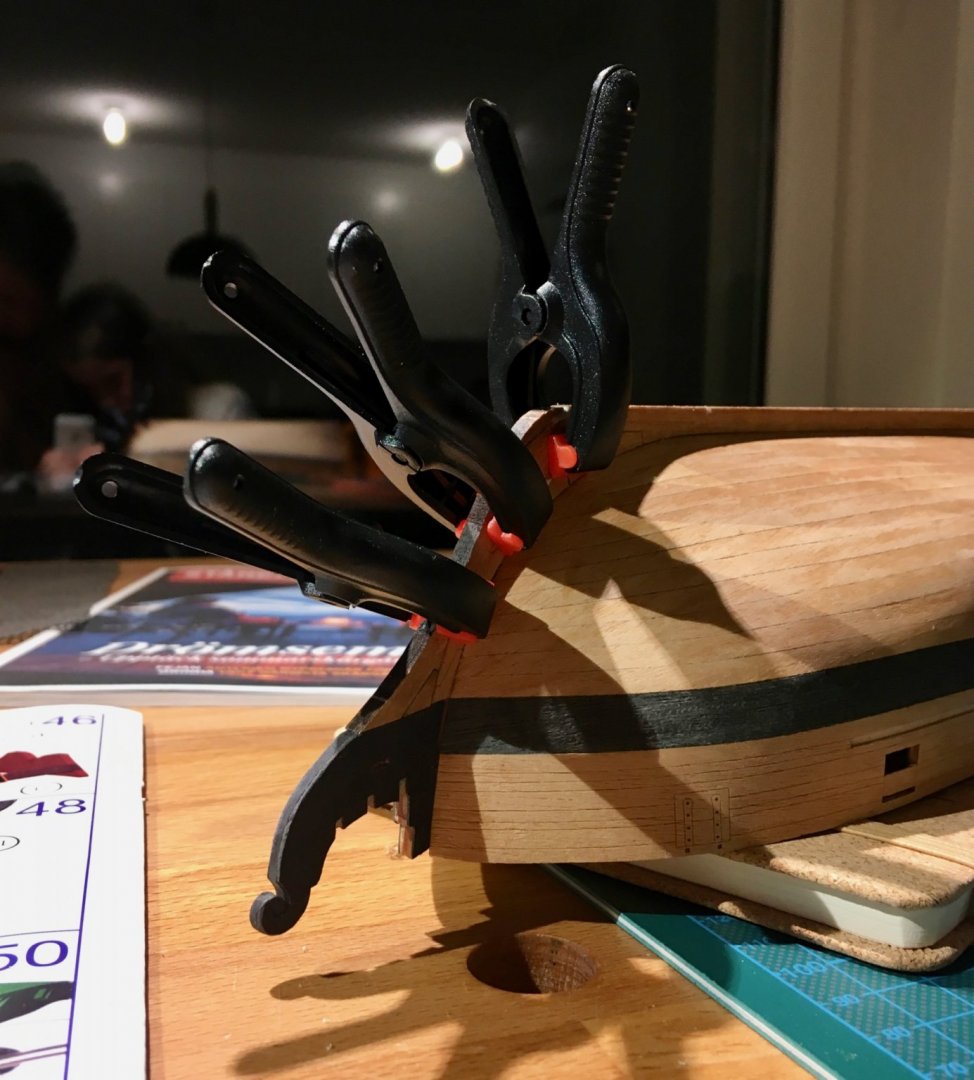
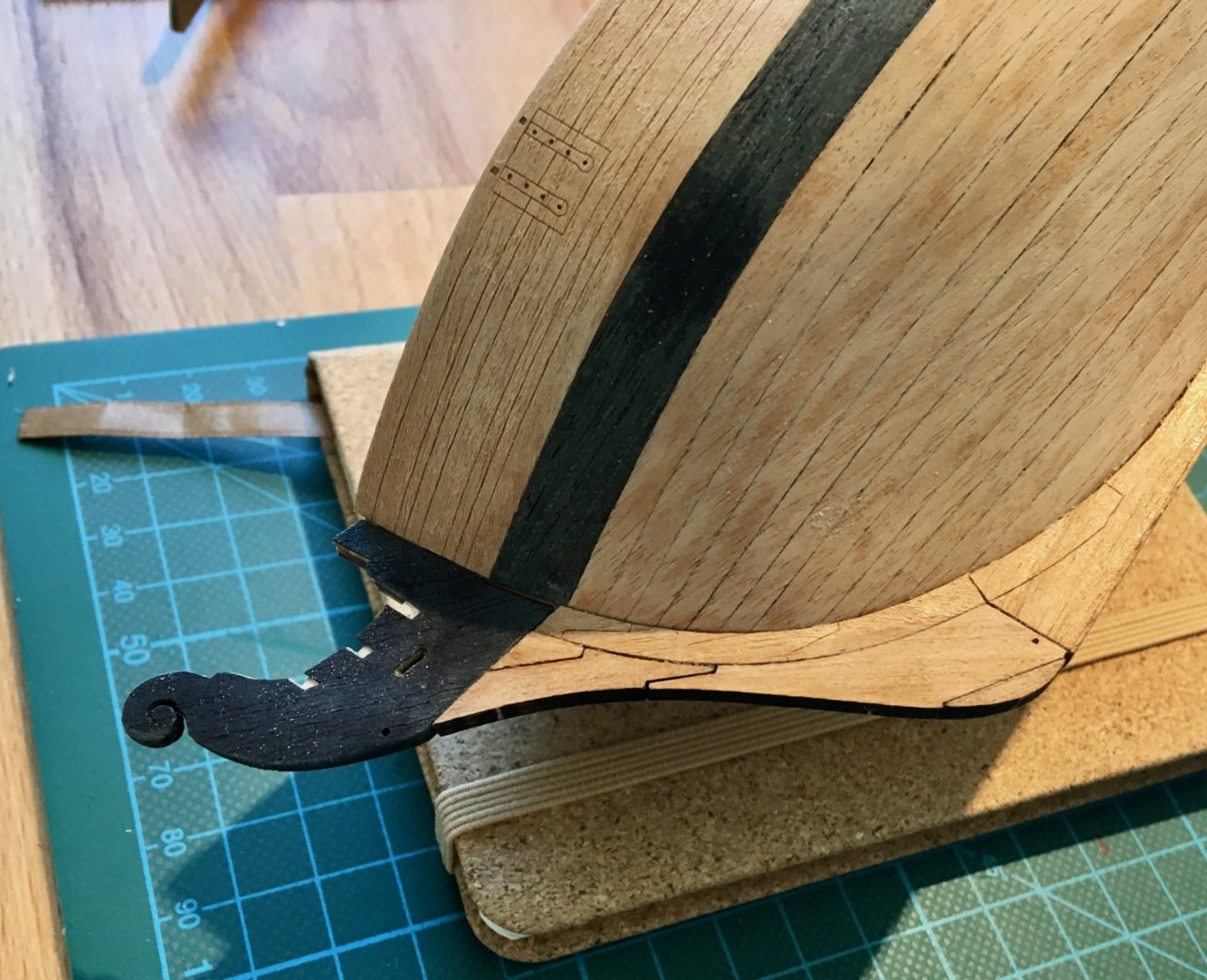
 This was an interesting part of the build, though pretty repetitive. I am glad that I took internal planking first, it would be barely visible, and a good practice before doing an external planking. One more time thanks to Chuck for showing how to edge bend. Got the hang of it, no more broken planks, and I get quite close to desired shape from first or sometimes second attempt: Got more Pfeil chisels, this time to simplify in-situ fairing. Works like a charm! Closer to deck clamps it became harder to clamp, so some awkward arrangements were used: The last streak was difficult. Even though I used tick marks, the last forward plank ended up a bit too narrow. Will be careful next time, does not worth re-doing this time. A blade is used as a wedge to press planks into each other in the areas of some gaps. More glue to soak into the gap. It is cheating, I know During the last few months I was sneaking to my modelling corner regularly (which is a challenge with a newborn), and managed to install all planks before the end of the year! Yay! I did not expect it to take this long though - with an average of 4-5 hours per streak and 14 streaks it sums up to 60-ish hours. So here is how it looks today, before treenailing / fairing / smoothing / trimming. When in display case, light coming from the bottom of the case goes through frames and makes an interesting pattern on the planks: There is plenty of dust over the model, that I will need to carefully remove after sanding. Hope to finish it in a near future and get to less repetitive parts (breast hooks, mast steps, deck structures, etc etc). But before that I need to decide on a finish to use (or maybe no finish at all), will make some test pieces and try all the sanding sealers that I bought last year. Also I got a surprising color deviation in planks, even though they are all cut from a few sheets of castello box, and sheets had no obvious discoloration. Maybe it is a side effect of heat bending, may go away after final sanding. Anyway it is not so bad, shows individual planks. A bit of deviation is good!
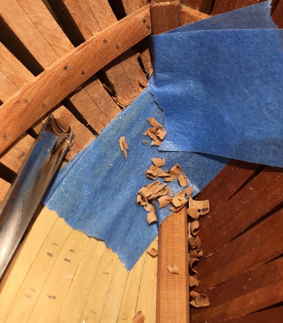


- 968 replies
-
- 28
-

-
- hahn
- oliver cromwell
- (and 1 more)
-
Very nice start!
-
Can i live without a BYRNES TABLE SAW
Mike Y replied to shihawk's topic in Modeling tools and Workshop Equipment
Not for modelling purposes, but as soon as you start making small woodworking projects, or even a display case for the model... -
Great layout! Hope it would work great for you. I would recommend to put a disk sander closer to your working area. It is by far the most used power tool when you make small things, once you are used to it.. Like who needs a table saw for cutting planks into proper lengths, where you can just cut rough dimensions using some wire cutters or any other simple tool, and then fine fit using a disk sander? Combined with some small household vaccuum to catch airborne dust - it is handy to have it close by. P.S.: consider an electric lifting table, it is actually the most used "tool" in my shop overall
-
Your workshop is very cosy!
-
Thanks Kris! This is very useful!
-
Make sawdust out of the wood you use for planking, mix it generously with a pva-based wood glue that dries clear-ish (not yellow) - that would give you a custom made filler for your wood
-
I was fooled by these renders as well, thought they were photos! Incredible! But what was a hint is the same look & feel for side grain and end grain. Frames will definitely look different comparing to deck planks. Any plans to build this beauty in wood?
-
Just noticed how beefy the deck beams are! Also you make a really nice cutouts!
- 589 replies
-
- 3
-
-
- le gros ventre
- cargo
- (and 1 more)
-
Oh, hope he would recover nicely. Best wishes!
-
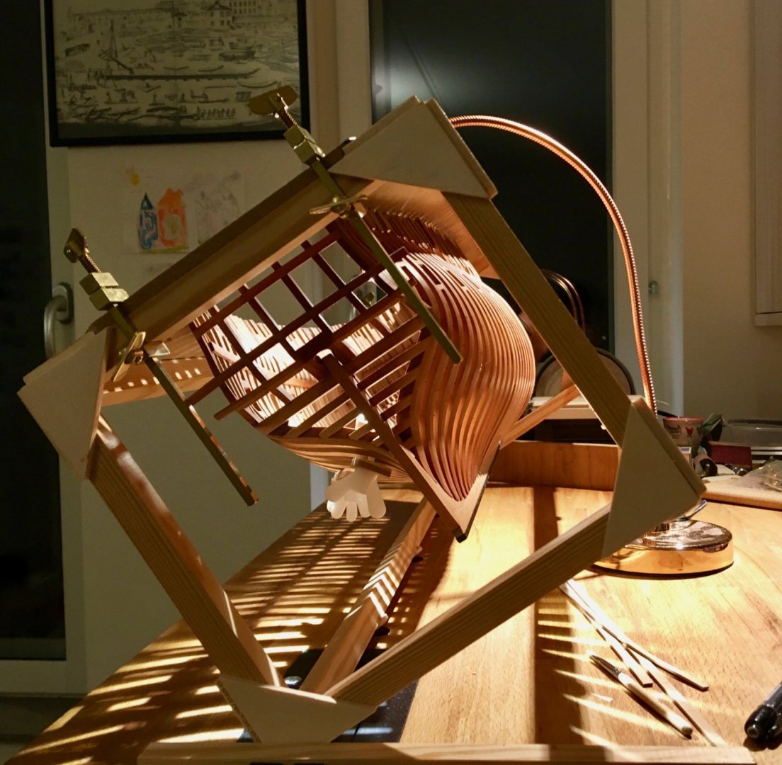
Thanks a lot for your comments! It is becoming increasingly difficult to clamp. Soon it would be a time to try the CA+PVA trick (using CA spots to fix the plank, while the PVA wood glue is setting). And some magic tricks that a Hahn jig allows you to do I love it more and more, it is so easy to position the hull on an angle when planking, avoiding glue drips and just generally orienting things the way you need. The key is to have a vice that can hold an entire jig.
- 968 replies
-
- 20
-
-
- hahn
- oliver cromwell
- (and 1 more)
-
Thanks Carl, Mark, Pontus and Grant! Grant, Daria is stretching her time between school, friends and various hobbies - she got into dances, bead bracelet weaving (with really tiny beads that are too small for adult fingers), and now nursing her little sister Emelie. We are still working on her model few times per month, more like our own little thing. Soon she is planning to get a pet rabbit, so her time would be even more limited. It is a good problem to have I'll sort out my model on my own, somehow. Even a few sessions per month is better than nothing. Everybody should have a getaway!
- 968 replies
-
- 6
-
-
- hahn
- oliver cromwell
- (and 1 more)
-
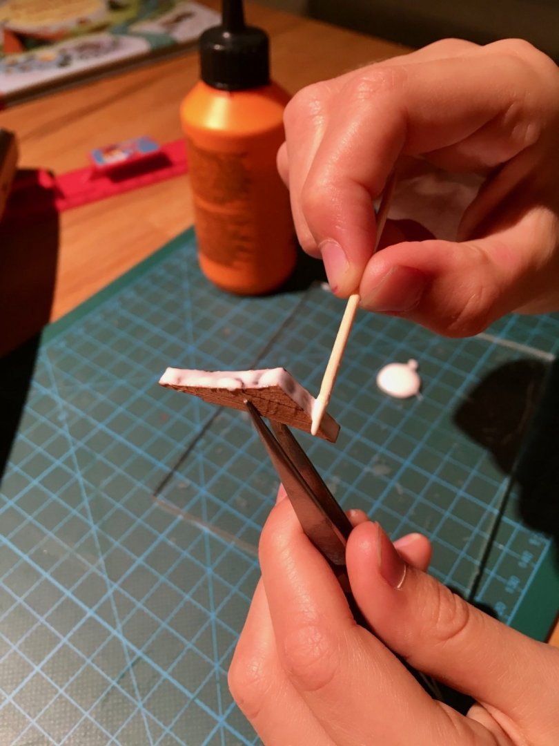
Construction progress is not so fast, for a good reason - we got a second daughter a month ago (yay!). Everything goes well so far, we are a lucky parents and Daria (the youngest) helps us a lot. But, as expected, there is little time for anything... Though I still sneak a plank every now and then, so it is moving with a pace faster than zero, one streak per week on average! Each plank takes from 1hr (for a simple straight planks midship) to 2-3hrs (curved ones with difficult shapes). Sometimes a plank goes to waste, so overall it is not a fast process. It is a nice to get a bit of your own time and work on a model, even late at night. Makes for a good photos Back to the build progress. Got quite comfortable with heat bending, pretty low error rate. But I still feel that the plank made this way is more brittle than the one shaped with steam. Luckily it is not a big issue. Since I did a bad job in fairing, there are some low spots that are fixed by adding a filler underneath the plank: Or chiseling away the high spots: Slow but steady, I passed the equator - 7 streaks done (plus limber streak), 6 remaining! Nothing is sanded yet, and considering bad fairing I expect to spend a lot of time scraping and sanding to make the planks look smooth and fair. There are a lot of glue traces, they would be cleaned up after treenailing. I'm glad I started with internal planking - it is a good training exercise, that would be barely visible on a finished model, hidden under all decks and cabins. Hope to get enough skill to do a better job on external planking Consider this a practice piece.


- 968 replies
-
- 29
-
-
- hahn
- oliver cromwell
- (and 1 more)
-
variable height desks
Mike Y replied to bigcreekdad's topic in Modeling tools and Workshop Equipment
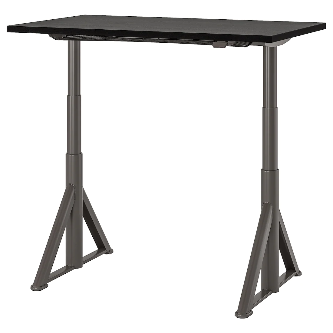
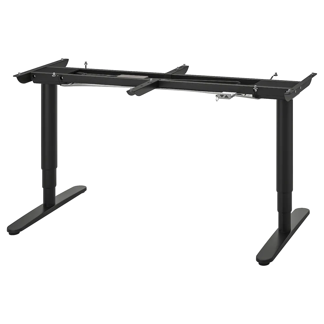
Checked IDÅSEN in IKEA. It is actually very good from technical point of view - hard to shake it even when on maximum height, very stable. It is flipped upside down comparing to BEKANT - wide parts of the telescopic legs are in the bottom, narrow ones are on top: Nice design of the control buttons - instead of pressing a button you pull a small lever up or down, very intuitive. I like it! There are two problems though: 1) They do not sell frame only, you buy it with a table top which is too weak for our purposes, it is an office table. So you need to buy a solid table top, making it more expensive. With BEKANT you can buy a frame and put any top on it, a bit cheaper. 2) Leg design, the look a bit ugly for my taste, and I will hit them with my feet all the time... Comparing to a flat design of BEKANT:

-
... still hoping that Glenn is doing well and will have an opportunity to come back to MSW some day soon
-
Hi Lawrence, Thanks! I am happy to report that the build is progressing, few planks per week, but slowly getting there. The camera is just a phone, iphone SE to be specific. No extra lenses. It is not always focusing ideally on the right part of the model, but I just make a series of photos from different angles and then pick the ones that are focused on the right places. My wife's iphone 8 is making even better photos, but I am too lazy to borrow it when needed A "proper" camera requires much more fiddling with white balance and such, and can do wonders in hands of people who knows how to use it (see Gaetan), but for a simple build photos any decent phone should be good enough.
- 968 replies
-
- 6
-
-
- hahn
- oliver cromwell
- (and 1 more)
-
Fantastic project! And the garden
-
ancre La Belle 1684 by Nenseth - 1:36 scale
Mike Y replied to Nenseth's topic in - Build logs for subjects built 1501 - 1750
Neat! Very nice shape Please keep them coming! -
ancre La Belle 1684 by Oliver1973 - 1/36
Mike Y replied to Oliver1973's topic in - Build logs for subjects built 1501 - 1750
Very interesting build, I am learning from your methods and jigs! -
Stem assembly required a bit of fitting and fairing, laser kerf was not taken into account when pieces were laid out. But overall the glue-up was going easy. There are some small gaps, but I decided not to be a perfectionist here Now the stem needs to be rounded and sanded: End result:


-
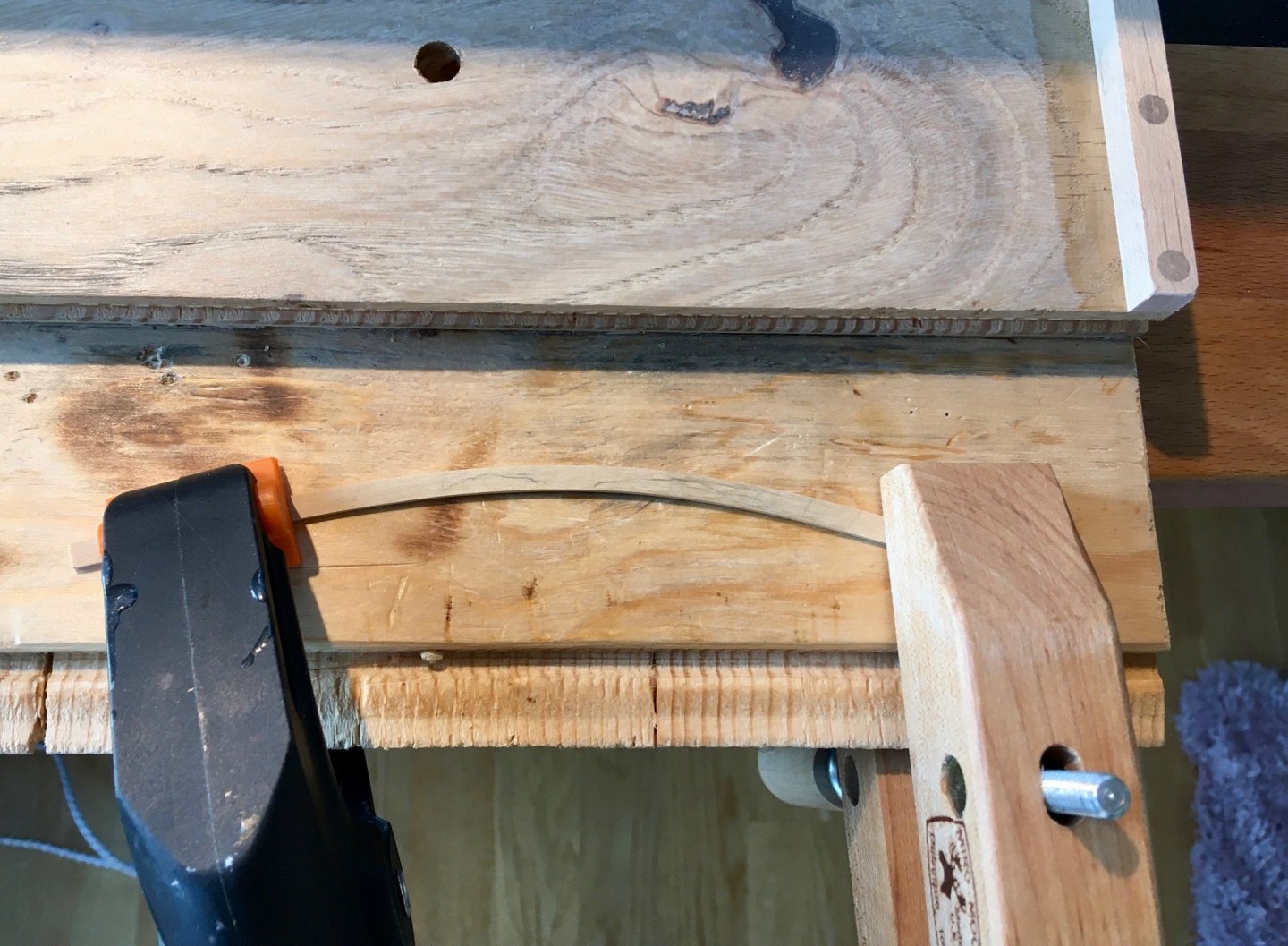
Yes, just bending a cold plank around the former would not work (tried it a few times) - the contact area is very small, so the plank can't get hot enough. So first I heat up the future bending area by using this aluminium former like a clothing iron, sliding it back and forth. Probably a clothing iron is even better, but I did not want to fiddle around with two hot tools at the same time. Only once the plank is hot - it can be hooked to the former and bent. Jorge, very nice solution! It is interesting that there are so many contraptions for the same job, and everybody have different preferences
- 968 replies
-
- 6
-
-
- hahn
- oliver cromwell
- (and 1 more)