-
Posts
13,362 -
Joined
-
Last visited
Content Type
Profiles
Forums
Gallery
Events
Everything posted by druxey
-

Cheers from Port Hope, Ontario, Canada
druxey replied to Peter Rumgay's topic in New member Introductions
Welcome, Peter. Check out the Marine Modellers of Niagara on the 'clubs' section of MSW. -
Oh, I'm sure you'll do a nice job on the kit 'as is'. But you may feel you want to kit bash a different kit later on.... Just sayin'!
- 109 replies
-
- Finished
- Artesania Latina
-
(and 1 more)
Tagged with:
-
Life happens! We understand, You'll get back to it when you can.
- 8 replies
-
- Model Shipways
- Lowell Grand Banks Dory
-
(and 1 more)
Tagged with:
-
Your comments on the kit scale fitting out make me think you are on your way to either kit-bashing (modifying the model as you build it) or even scratch building!
- 109 replies
-
- Finished
- Artesania Latina
-
(and 1 more)
Tagged with:
-
If you must use wire wool, use bronze not steel for the reasons given above. However, it's hard to find these days.
-
That is one of the critical points in forming the quarter gallery; everything is parallel to each other. You should be fine from here on.
- 399 replies
-
- winchelsea
- Syren Ship Model Company
-
(and 1 more)
Tagged with:
-

Ships name 1700s
druxey replied to DaveBaxt's topic in Discussion for a Ship's Deck Furniture, Guns, boats and other Fittings
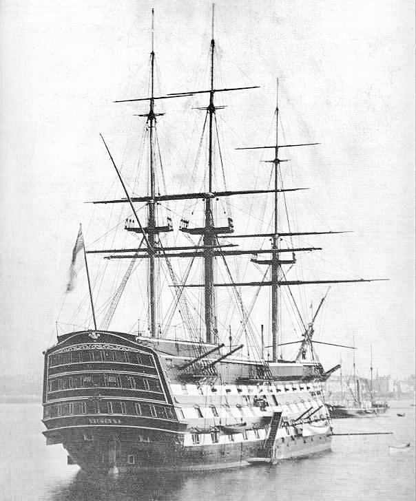
B. E.: I know that the French usually showed the ship's name in a compartment on the counter, but was not aware of this being done by the British in the early 19th century. Victory's name was certainly seen this way in early 1900's photographs (below), and persisted until changed to something more appropriate recently. -
Wet and dry paper is used for metal, not wood. This, and the fact you are using extremely fine grades is why you are getting clogging. Garnet, emery, aluminum oxide and silicon carbide are used on wood. See: https://www.empireabrasives.com/blog/sandpaper-grit/ Usually, for wood, 400-grit is as fine as you need to go.
-
Best wishes as you manage an elderly parent. It's never easy.
- 2,699 replies
-
- heller
- soleil royal
-
(and 9 more)
Tagged with:
-

Ships name 1700s
druxey replied to DaveBaxt's topic in Discussion for a Ship's Deck Furniture, Guns, boats and other Fittings
British ships' names appeared across their counters officially in 1772, although this may have formally been done for a few years earlier. The practice seems to have been discontinued during the Napoleonic wars. -

Soft, medium or stiff brushes?
druxey replied to CPDDET's topic in Painting, finishing and weathering products and techniques
Look after a good quality sable and it will last you years. I have some over 30 years old and they are still in good shape. Cheap brushes are a snare and delusion. You have to keep buying them over and over and they will shed hairs in your beautiful fresh coat of paint! -

Swan-Class Sloop by Stuglo - FINISHED - 1:48
druxey replied to stuglo's topic in - Build logs for subjects built 1751 - 1800
The illustration shows full-size practice. You can cheat, as long as the end-result looks right.- 475 replies
-
Glad you had such a good time. I'm so sorry that I had to miss the great showing this time. U.S.: Why you no open land border to nice, polite, vaccinated Canadians?
- 2,699 replies
-
- heller
- soleil royal
-
(and 9 more)
Tagged with:
About us
Modelshipworld - Advancing Ship Modeling through Research
SSL Secured
Your security is important for us so this Website is SSL-Secured
NRG Mailing Address
Nautical Research Guild
237 South Lincoln Street
Westmont IL, 60559-1917
Model Ship World ® and the MSW logo are Registered Trademarks, and belong to the Nautical Research Guild (United States Patent and Trademark Office: No. 6,929,264 & No. 6,929,274, registered Dec. 20, 2022)
Helpful Links
About the NRG
If you enjoy building ship models that are historically accurate as well as beautiful, then The Nautical Research Guild (NRG) is just right for you.
The Guild is a non-profit educational organization whose mission is to “Advance Ship Modeling Through Research”. We provide support to our members in their efforts to raise the quality of their model ships.
The Nautical Research Guild has published our world-renowned quarterly magazine, The Nautical Research Journal, since 1955. The pages of the Journal are full of articles by accomplished ship modelers who show you how they create those exquisite details on their models, and by maritime historians who show you the correct details to build. The Journal is available in both print and digital editions. Go to the NRG web site (www.thenrg.org) to download a complimentary digital copy of the Journal. The NRG also publishes plan sets, books and compilations of back issues of the Journal and the former Ships in Scale and Model Ship Builder magazines.


