


CaptainSteve
-
Posts
1,857 -
Joined
-
Last visited
Content Type
Profiles
Forums
Gallery
Events
Posts posted by CaptainSteve
-
-
-
Absolutely stunning, Jon. Methinks I shall be stealin' ideas from you now.

-
Probably a good idea to mount your sails (furled and otherwise) to the spars before you fix them in place. If you are looking for ideas for your sails, check out some of JerseyCityFrankie's work.
(By the way, your first picture above makes your ship appear to be some kinda Dystopian bird trying to take flight)
-
There's been a lot of that OBL stuff going around, Sam ... especially around my ship-yard.
'Tis good to see you back on deck.
- src, mtaylor, popeye the sailor and 1 other
-
 4
4
-
-
Beautifully detailed work, Dave ... and, unlike me, they didn't take you a whole year to do.

- mtaylor, Piet, SawdustDave and 2 others
-
5
-
-
I built OcCre's Apostol Felipe some ten years back. They had translations in four languages, but the information was quite scant. Seeing Heronguy's posting above, it looks like they have improved their game. For the most part, I followed the photographic guide, ticking off each step as I went.
All in all, it was a great kit that turned out to be a great model. I'd definitely recommend them.
-
Great to see that you are back at it with gusto, Mark.
- Jack12477, EJ_L, popeye the sailor and 5 others
-
8
-
Paul. I've mentioned before that this was my very first build, too. You are doing waaay better than I ever did !!
With regards the rigging, I just followed the numbers. Do two or three (or four or five) lines each night, and you'll get there in no time at all. I think your decision to leave the stay-lines temporarily unattached will prove very wise. I do recall experiencing difficulties getting my fat fingers in to tie lines off to the belaying pins.
You may find that you will need to fix the stays and rat-lines before the rigging is finished, as some later lines tie-off to the rat-lines (flying rigging).
Have you considered pre-making some rope coils ?? You'll need about 40 or more. Tie off your lines to the pins, super-glue in place, trim the excess rope, and slip a coil over the belaying pin. Use a diluted PVA mix (about 30 PVA/70 H2O) and "paint" a bit onto your coils and then shape them into place with your tweezers, so that they will permanently hang down convincingly.
Also, I found left-over rope coils to be very useful for hiding mistakes (obviously, YOU won't be requiring those).
When I was rigging the upper masts, I found it quite tiring on the wrists/forearms. Never tried this myself, but mayhaps you could try setting your model at ground level for these sections.
Keep up the great work !!
-
-
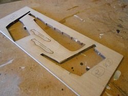
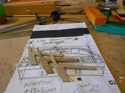
Must've missed this one myself, Jon. Probably because I have only ever tried to loosely dry-fit the many attempts at this section. For some stupid reason, I had just assumed that if I stuck to the same height as the laser-cut pieces then I would be okay. This was one reason why every frame that I have cut for re-builds was made to fit that modified template (pic 1 above).
A quick dash to the modelling room and, unfortunately, I think that you may be right !!

This will mean that the ceiling will be lower. This is going to drastically affect the window size and placement, since these have to sit between the 'knuckle' of the transom, and the lower edge of the roof-beam part of the transom frames.
I'm up for another re-build, ain't I ??
PS: A couple of quick pics from my build ...
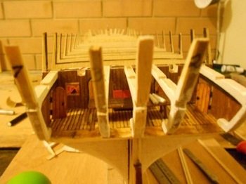
All of these frames were cut to match that template. Here, the height appears okay. Yet, in my current attempt, the error you show seems to appear.
Most perplexing ?!?!?
-
-
Another "Gotcha !!"
You had me dashing for my copy of AOTS again, KMart. I see what you mean. They definitely do appear to be more uniform in Marquardt's book, as opposed to the MS plans. A cursory flick thru a Google Images search seems to bear this out, but hard to tell precisely with most of the pics I found online.
Personally, I think even-spacing would look better on the overall model. The next question is: Will this be possible, given the positioning of the bulkheads ??
- zappto and Bill Morrison
-
2
-
Not sure about the "courage (and) tenacity" part, Jon. Certainly "stubborn", with a not-so-healthy dose of OCD thrown into the mix.
Okay. I've edited the above post with slightly bigger pictures (didn't want to photo-bomb your log). Hope that makes it easier for you. Any questions, just feel free to ask.
-
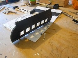
Jon. My apologies for becoming somewhat stalled on my own build. 'Tis true that this area is proving tricky, and the problems you have noted above are exactly those that I have encountered. Although I haven't been documenting them all in my build log, I have made a number of attempts to get this section the way I want it to be. If it helps you at all, I have now opted to not have the uprights sitting angled, as my log currently shows. This just wasn't working for me !! I'm now using just the template from one of the stern frames as an outline, and cutting only three stern frames: port, starboard and central. I am cutting an upper and lower piece to form the window frames. Note the notches on the backs of the stern frame pieces (pic is a bit small) still need to be chiseled out, which will be where the window frames will sit. Here's some pics from my latest attempt to demonstrate what I mean:
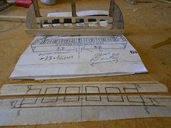
I modified this laser-cut piece slightly to Port, Central and Starboard frames. The Window frames in two pieces. These fit
use as the template for the three frames. uprights on the outer ones are a bit into recesses cut into the backs of the
shorter than the centre one. frames.
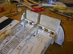
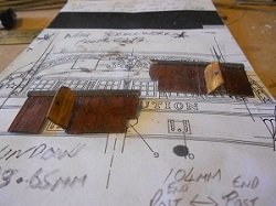
Looking from the inside at an earlier Other side of last picture. This one was Internal doors leading to side galleries,
(failed) attempt. close, but the windows just weren't quite for when I (eventually) get this section
correct. right !!!
Hope these give you a few ideas for your own work, and thanks for motivating me back into my own modelling room for this weekend, at the least. Keep up the great work.
- usedtosail, MEDDO, Blue Pilot and 1 other
-
4
-
-
-
-
Is that what they mean when they say "Once you go black, you can never go back" ??
Sweet ride, Michael !!
(... and, Yes, I AM jealous)
-
Outstanding work, Tom ... she looks beautiful !!
-
-
She's a beautiful girl, Nenad.
- Piet, Omega1234, popeye the sailor and 2 others
-
5
-
UdoK,
I found the following news article about the Batavia this morning. Thought that you might find this interesting.
Nice work so far.
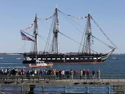
USS Constitution by Tom Schongar - Model Shipways
in - Kit build logs for subjects built from 1751 - 1800
Posted
Looking good, Tom. You are powering ahead. Just a minor point, but looking at your second picture, I'm wondering if your transom extensions aren't set a little high. Check out Sheet 2, up at the top of the page (Detail 2-H).
O'course, I could be wrong ...
(Which would go a long way towards explaining all my re-dos)