


rvchima
-
Posts
649 -
Joined
-
Last visited
Content Type
Profiles
Forums
Gallery
Events
Posts posted by rvchima
-
-
Superstructure
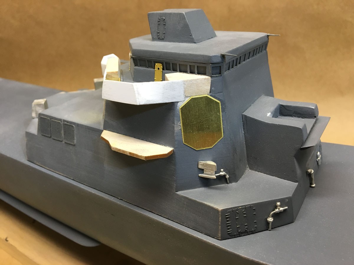
I've added a lot of detail parts to the superstructure - extensions around the top of the stacks, ladders, antennas, etc. I painted everything Haze gray using the Testors paints that I bought with the kit, and a cheap Badger airbrush. The horizontal deck surfaces on the aft superstructure are painted Euro gray using a brush and a lot of masking tape.
Speaking of antennas, the two antennas on the front of the aft superstructure are cast metal pieces that are butt-glued to a photo-etched platform. Well I've broken the platform and antennas off more times than I can remember, so the other day I deconstructed everything, drilled two holes in the platform, glued it back with a 1/32" brace underneath, and epoxied the antennas in the holes. They aren't going anywhere now.
Then today when I went to take this photo I broke the single antenna off the front stack. Looks like more deconstruction ahead.
-
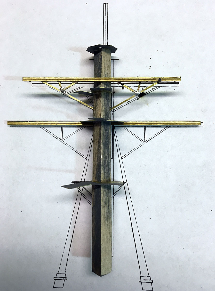
Mast Construction, 32 days, 90 hours
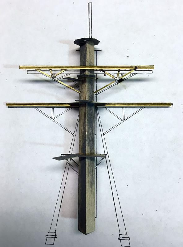
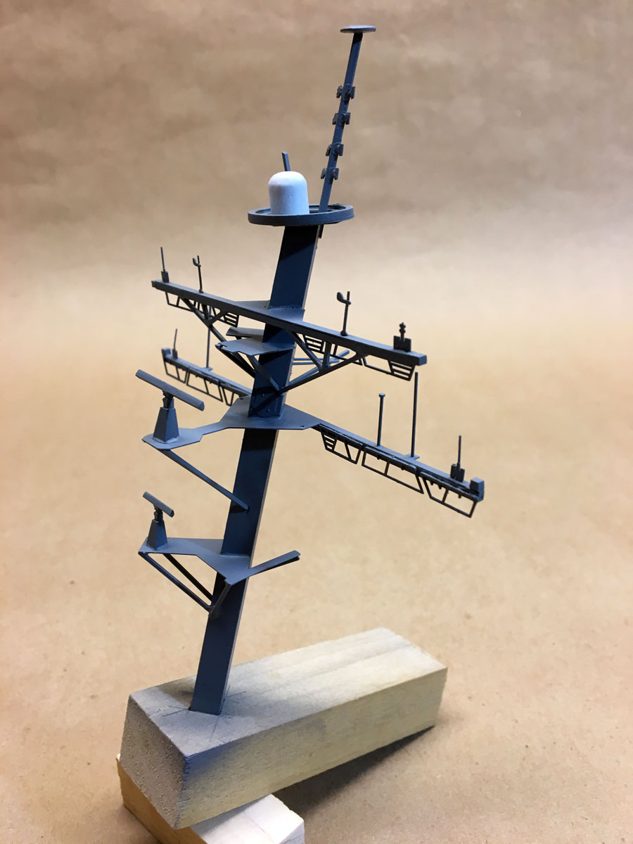
The mast is made from 1/4" square basswood set on the diagonal and swept back 15 degrees. The yards are photo-etched brass reinforced with 1/16" square brass tubes glued with CA.
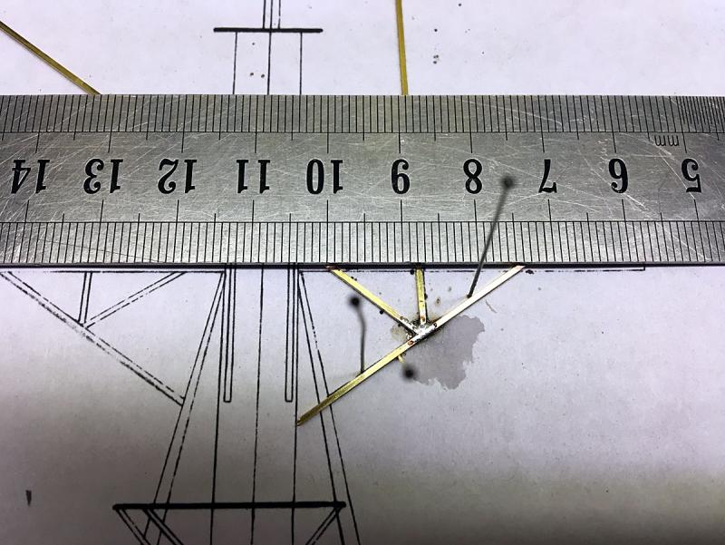
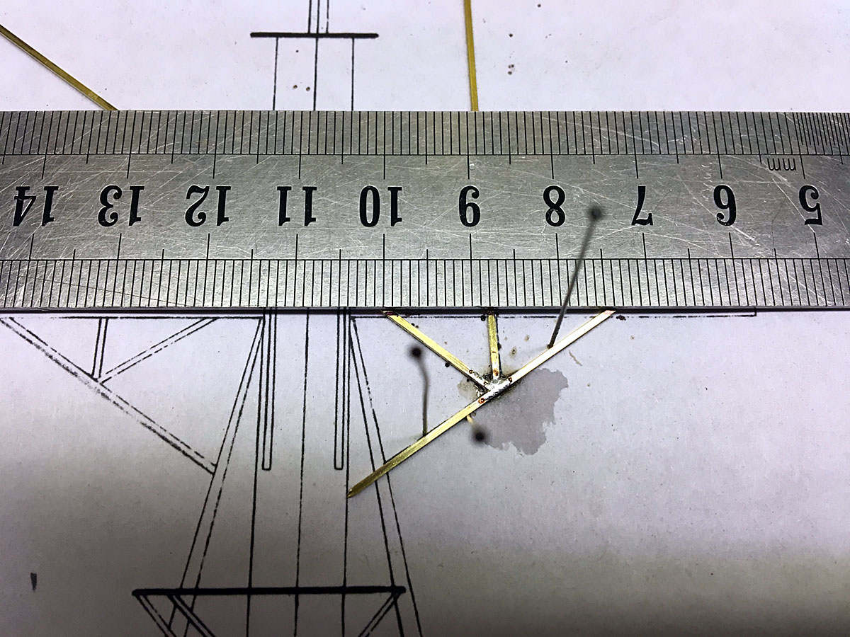
The yard braces are made from 1/32" square brass stock. The instructions said to glue these pieces together, but when it was time to sand them flush they just broke off. Instead I soldered the main joint with long pieces, cut the braces slightly long with wire cutters, then sanded everything flush on a Proxxon disk sander. My other hobby is stained glass so I've done a lot of soldering.

It was hard to hold the mast in my vise because it is set on the diagonal, so I chopped a square hole in a piece of poplar to make a holder.
To make the platform braces I spun the brass stock against the sander to make a point that I shoved into the mast. I clipped the other end slightly long, sanded the end to match the platform, and glued both ends with CA. They are super strong.
The mast has a zillion tiny photo-etched pieces. I put on my magnifying headset and started snipping, filing, and gluing. The 8 little antennas on the top mast extension are about the size of a grain of rice and were especially hard. It's good that the kit includes lots of spares because several pieces went flying, never to be seen again. The two radar antennas are cast pieces.
The mast took about 20 hours to build. It was challenging but actually a lot of fun, and it looks beautiful.
-
Resin Parts
After my problems with the resin prop shaft pieces I decided to check all the resin parts. I discovered that one radar unit was missing and several parts had serious voids. I emailed Bluejacket and received a quick response from Nic. It took a couple of weeks to get the replacement parts, but I'm not ready for them yet anyway. The new parts look good.
- Ryland Craze, JPAM, WackoWolf and 4 others
-
 7
7
-
Hi Tim,
I noticed in your post on my Arleigh-Burke build that you had built several Bluejacket kits, and I finally got around to looking at your build logs. Now I'm sorry I waited so long! I got so many great tips:
- Bondo glazing putty
- Krylon textured shimmer paint
- The Glue Looper
- PE bending tool
I'll be following this liberty ship build closely to see what else I can learn.
One question - have you found any spray paint that matches the Model Master haze gray sold for the Bluejacket kits, or are you using an airbrush now?
Rod
-
US Naval Academy Museum, Annapolis MD
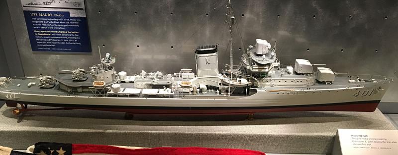
Last weekend my wife Cinda Williams Chima and I went to the Baltimore Bookfest. She writes fantasy novels for young adults. I took a day off and visited the US Naval Academy Museum in Annapolis, MD. The first floor of the museum has a history of the US Navy with plenty of ship models. The second floor houses the Rogers Ship Model Collection with 108 ship models from 1650 to 1850.
Azzoun gave a great description of the museum on MSW back in 2014, so I won't repeat everything here. I'll just state that this was one of the most amazing collection of ship models that I've ever seen. It made me want to go home and try harder. This spectacular model of the USS Maury might give you an idea what I'm talking about.
-
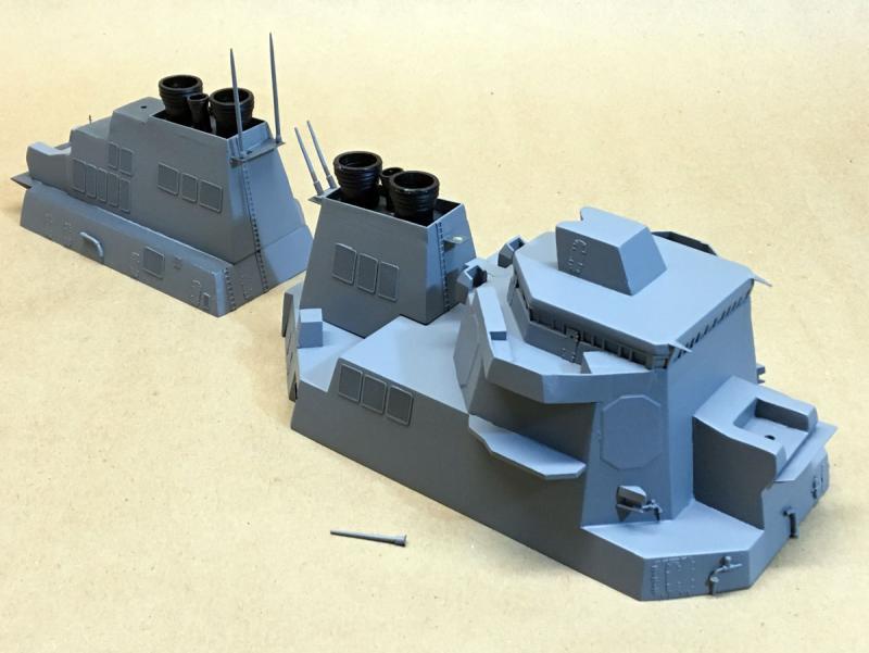
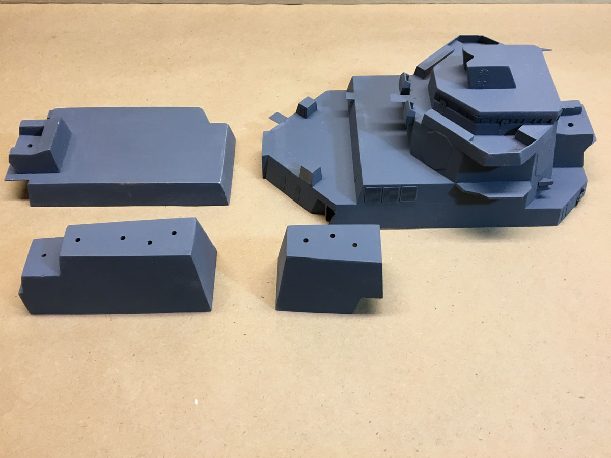
Superstructure 20 days, 53 hours
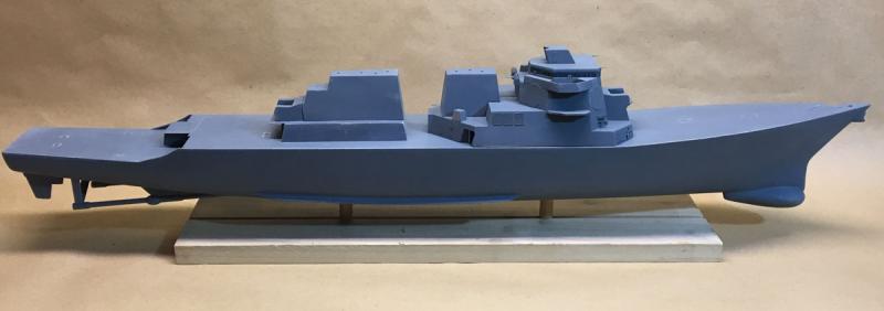
Much of the superstructure is roughed out and she's starting to look like a real ship. Of course the components are just laying here and are only primed, not painted.
The model is listed as one of Bluejacket's most difficult kits but it is coming along surprisingly quickly. I know I still have a million little parts to attach, but I would say that it has been pretty easy going so far.
Forward Superstructure

Building the forward superstructure was fairly straightforward. All the decks are laser-cut basswood. They are removed from the carrier board, glued along the centerline, then stacked vertically. After a layer is glued up, the angles are sanded with the piece upside down on a disk sander. Laser-cut angle jigs are included to set the table.
IMPORTANT NOTE: YOU MUST HAVE A DISK SANDER TO BUILD THIS MODEL.
Then several layers are stacked to complete the forward superstructure. Sounds easy, right? Well not always. Although the instructions show several views of the stacked pieces, it isn't usually clear how they all go together and line up. Some of the pieces are not cut to quite the right profile, and it's hard to get the right profile off the plans. One of the pieces is sanded upside down and 0.01" undersized to make room for windows. Not easy to do.
After everything is stacked up you apply lots of photo-etched and cast metal detail pieces. There is a whole page of instructions like the following: "Mark the location of the FAS brackets (FAB-39) on the forward angled face of the 03 level and glue them in place." WTF does this mean?
I have no idea what a FAS bracket is, so that's no help. The instructions refer to level 01, 02, 03, but nowhere on the plans are the levels labeled. You can try to guess, but it's just not clear where the levels spit.
The parts are all labeled with a code. F stands for Fabricated, or cast metal, PE stands for photo-etched, etc. AB stands for Arleigh-Burke, so (almost) every part has a redundant AB in its name. The final number is the part number. The photo-etched carrier sheet has part numbers all over it and they are relatively easy to identify. The several hundred cast metal pieces are sealed in lots of plastic bubbles in no obvious order. They are not labeled anywhere. The only way to identify them is to find the part number on the plans, then identify the part by its shape. There are several problems with that idea.
1. Some of the parts seem to be mis-numbered in the instructions.
2. There is no obvious cast metal counterpart for some of the parts shown on the plans.
3. Most of the parts on the plans are not labeled at all.
After struggling through the page of instructions there were still dozens of parts on the plans that had not been attached. Maybe they'll show up on a subsequent page, but I just decided to find parts that looked like the plans and glue them in place.
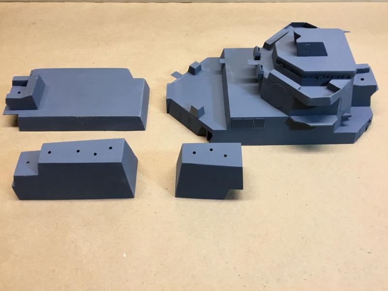
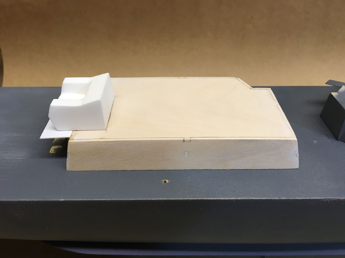
Aft Superstructure

While the forward superstructure is all made up of solid stock, the aft superstructure is glued up as an angled box of laser-cut pieces. This piece would have been much easier to make from stacked solid wood.
The back end of the aft superstructure is a mount for the Gatling gun made out of cast resin. There is a similar piece on the forward superstructure. Both pieces are basically angled boxes with a notch cut in them. They would have been so easy to make with wood. I can't imagine why Bluejacket decided to cast them.
Stacks
The stack are made like the aft superstructure, by gluing up a box of laser-cut pieces. There are still LOTS of grills, doors, and pipes to be attached.
-
Jud,
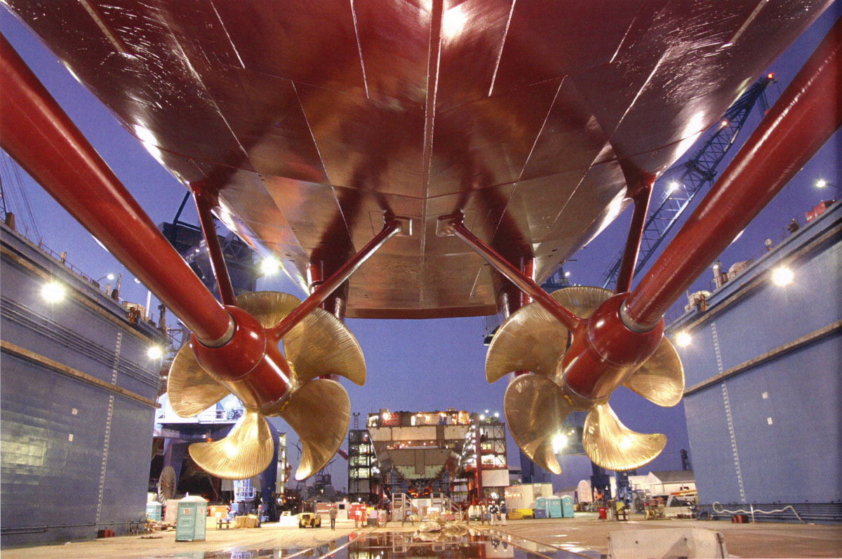
Thanks for posting the photo of the USS Ammen. The prop shafts appear identical to the Arleigh-Burke, but the Ammen props have 3 blades while the A-B props have 5. (see below.)
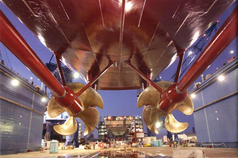
The props in the kit have a metal hub and photo-etched brass blades. I haven't built them yet but they didn't seem nice enough, so I ordered a pair of of 25mm cast props from http://www.model-dockyard.com/. I'll decide what to use when they come.
-
Progress, Frustration, and more Progress 4 days, 21 hours
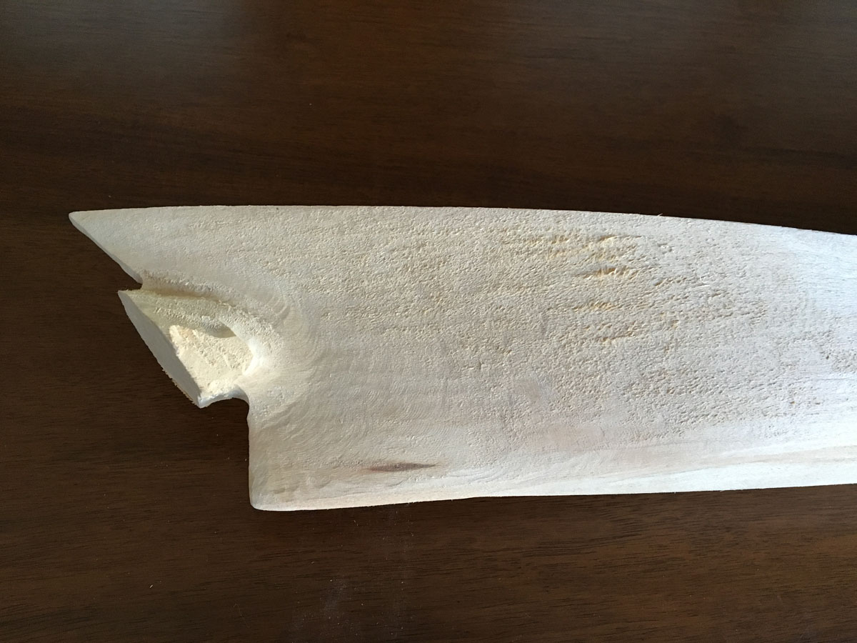
The first step on the Arleigh Burke kit, cleaning up the hull, was easy. I trimmed off the attachment points freehand on the band saw, removed the rest with a gouge, and cleaned up everything with a palm sander. The hull shape was nearly perfect but I had to remove a little material aft to match the deck plan. The back step on the aft deck is cut square but should be sloped inward a few degrees. I cut that on a table saw.
Then the project became frustrating.
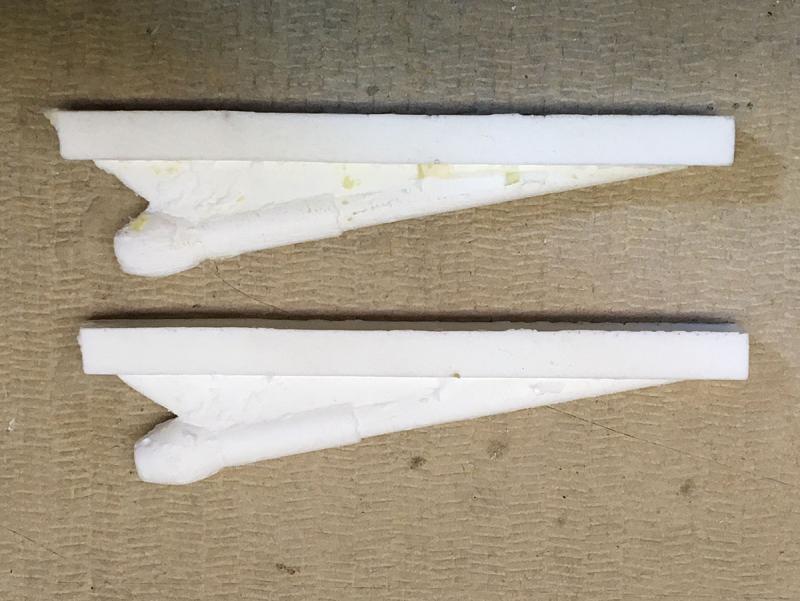
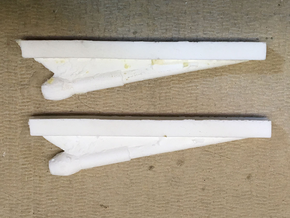
The cast resin prop shaft attachments were some of the worst cast pieces that I've ever seen. Not only were they full of pits, but they were covered with extraneous nubs and debris. Bluejacket should be embarrassed to include them in such a high-priced kit. I spent several hours sanding, filing, and filling and still was not happy with the result.
The prop shaft assembly consists of the resin attachment point, a flexible styrene shaft, and a cast pot-metal strut. The strut looked OK until I realized how soft the metal was. I could just imagine the flexible metal strut and flexible styrene shaft bending over the first time I bumped the model.
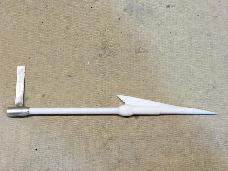
There is no indication on the plans as to where the strut attaches to the hull, whether it should be vertical or angled. A short search on-line showed that the Arleigh-Burke has two angled struts on each prop shaft. I gave up on the resin/styrene/pot-metal construction and built my own prop shafts.
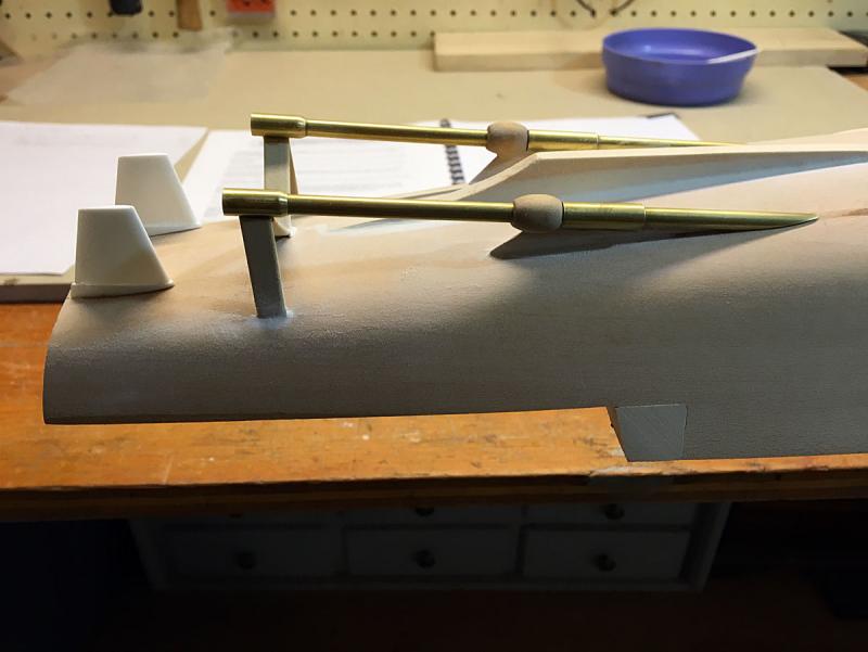
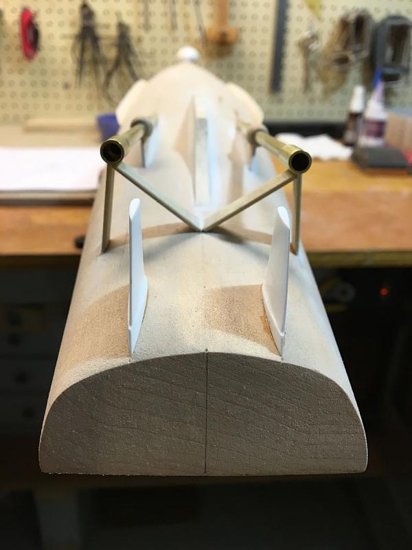
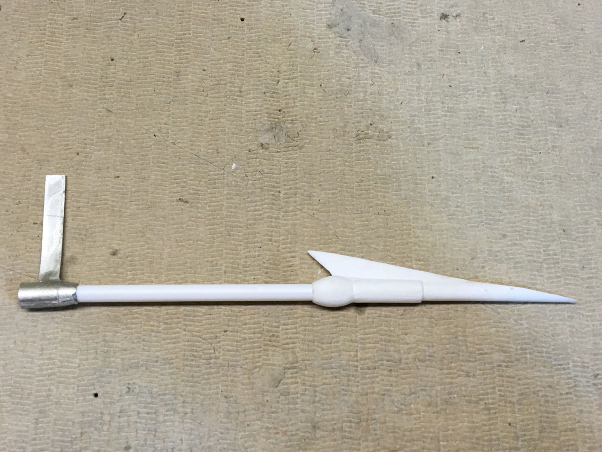
My prop shafts are made out of brass tubing with wooden struts. I spun the egg-shaped bearings on my drill press and sanded them to shape. There are two struts on each shaft. One is nearly vertical and the other slopes inward to the hull center line. The whole assembly is rock solid and looks so much better than what came with the kit. The rudders were also cast resin and were flawless.
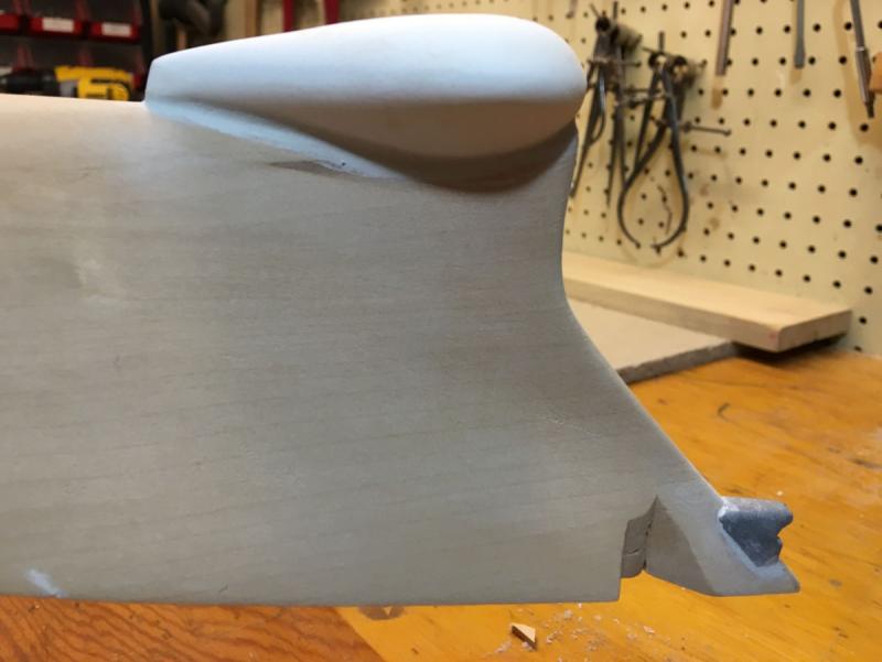
The sonar unit is contained in the bulbous bow of the ship that reduces wave drag. On the model the bulb is made of cast resin. It had a few pits but was usable. I had to carve the bow to get it to fit into the slot in the bulb. I still need to do some sanding on the filler at the edges.
The anchor chain will go through a hawse pipe drilled through the bow. The hole is lined with more styrene tube. I expected a cast metal fitting for the bow, but the instructions said to use a "suitable filler" to build my own. I used 5-minute epoxy putty that I rough-shaped by hand, then carved after it was solid. I guess it looks OK, but still another disappointment from an expensive kit.
- Robin Lous, GuntherMT, RichardG and 12 others
-
15
-
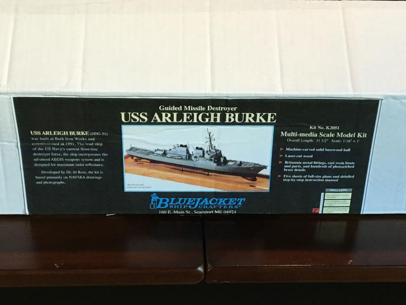
USS Arleigh Burke guided missile destroyer
I recently took a trans-Atlantic cruise from Rotterdam to Norway, Scotland, Iceland, Greenland, Newfoundland, Nova Scotia, and Boston. I saw so many unusual ships, both models and full sized, that I had to start another model. I was intrigued by the Aeronaut Bismarck model, but I couldn't find any useful reviews. Please let me know if you've had any experience with their kits.
Bluejacket Shipcrafters has a couple of WWII kits, but their kit of the Arleigh Burke guided missile destroyer caught my eye and I ordered it. It is by far the most expensive kit that I've ever bought. Please don't tell my wife. Is it worth the price? Well, lets see what's
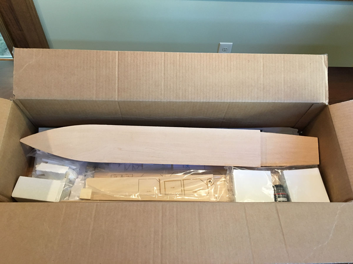
Inside The Box
The model came in a large box packed full of styrofoam peanuts. It was a pain to separate the parts from the junk.

Here's what was inside.
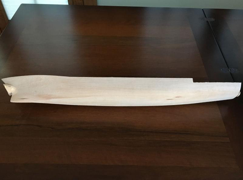
The hull is machine-carved from a single piece of basswood.
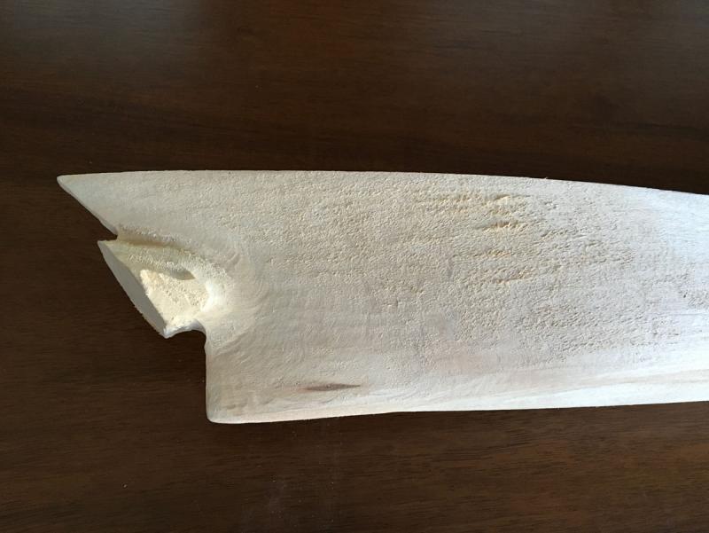
The hull shape looks very good, but there are still attachment points that will have to be carved away.
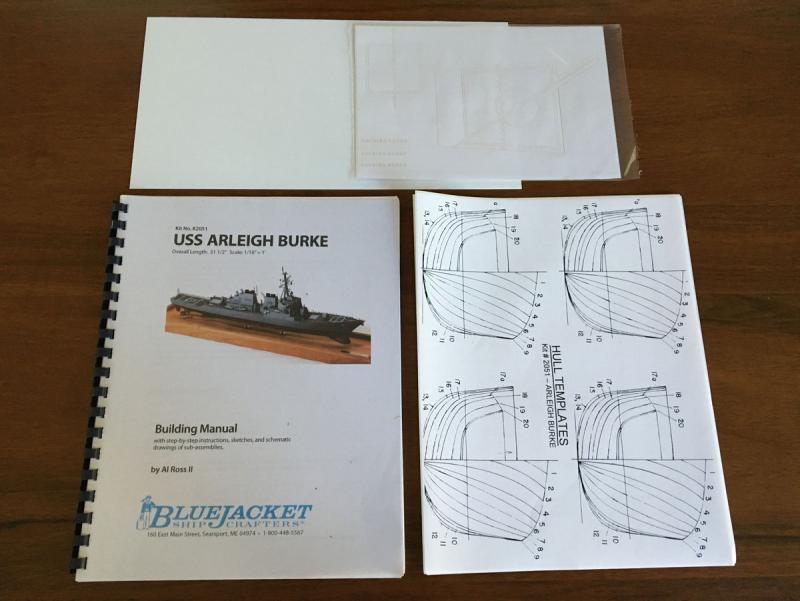
There is a 65-page instruction manual that seems to be very thorough. Bluejacket offers a CD of build photos for an additional fee. I didn't order it. The kit includes hull templates printed on self-adhesive paper, a guide for painting the helicopter landing marks on the deck, and a big piece of styrene for God knows what.

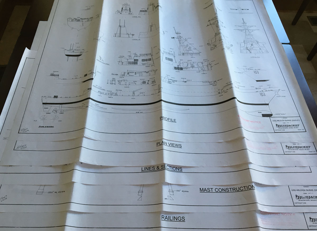
The kit includes 5 pages of plans. You should be able to see the titles in the photo.

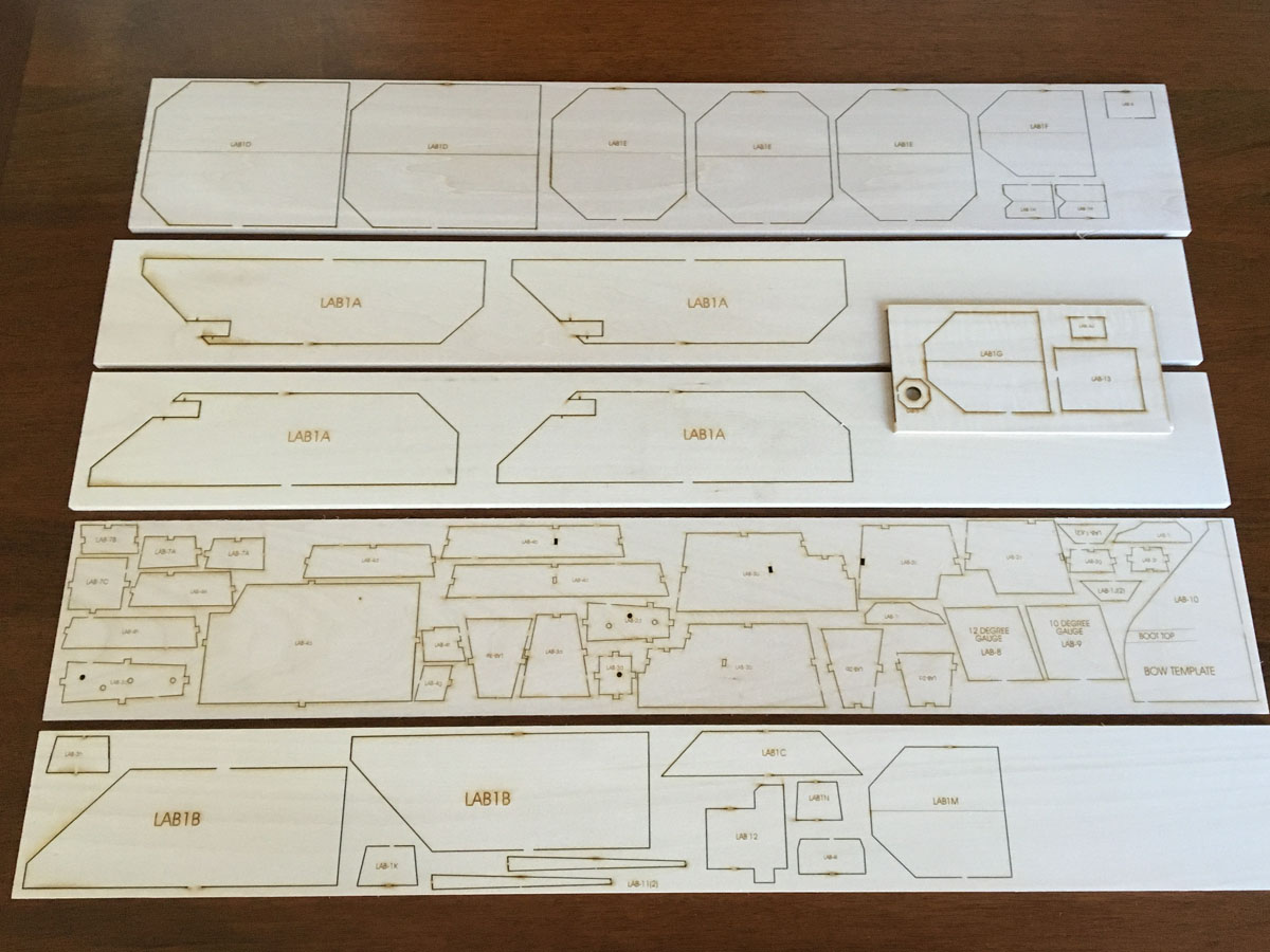
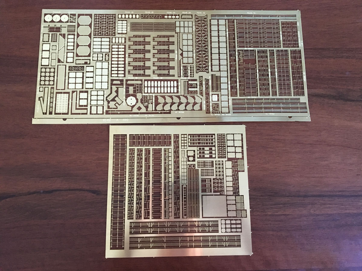
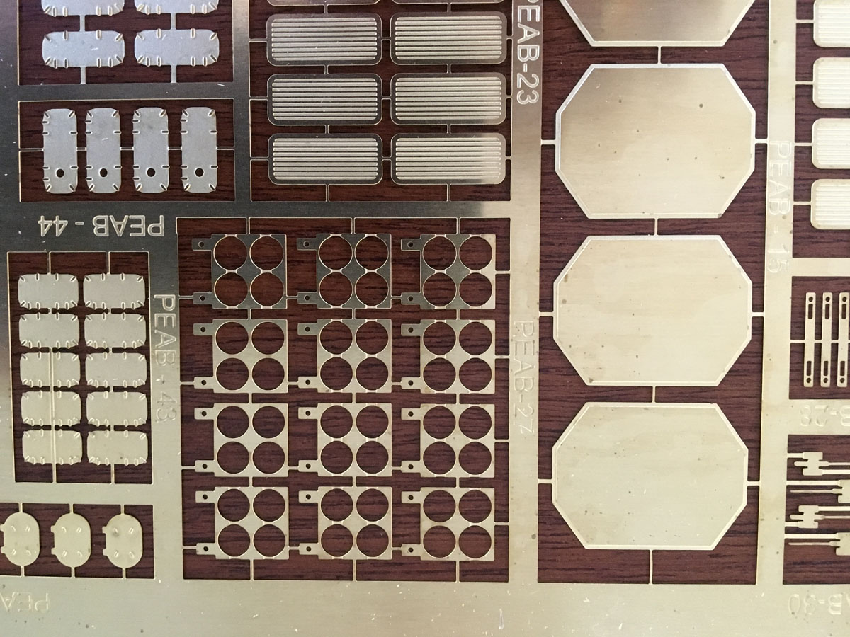
There are 5 sheets of laser-cut parts. The cut lines are crisp and nearly free of char. All of the deck superstructure will be made from these parts.
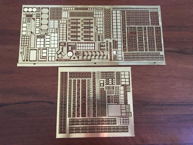

The instructions say that there are over 600 photo-etched parts. Whew.
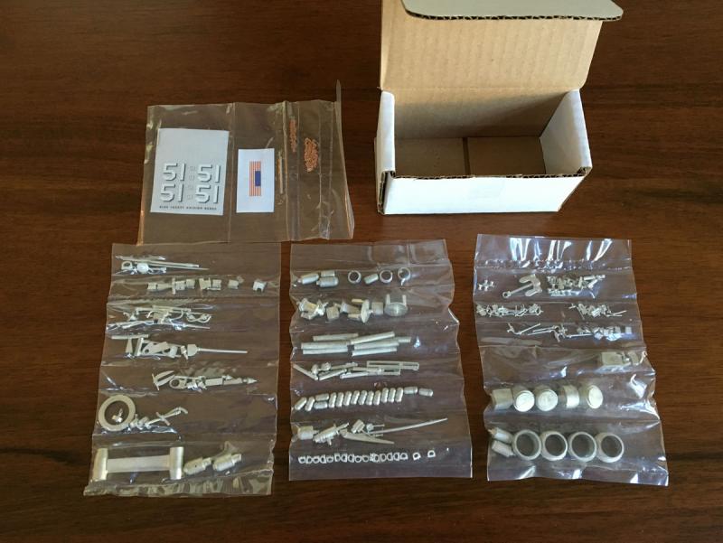
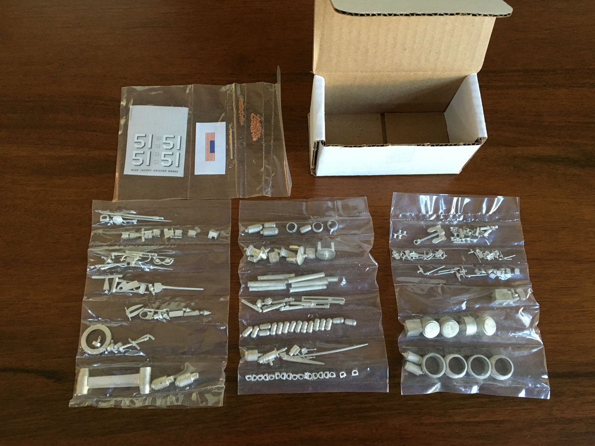
The kit had a tiny box packed full of beautiful cast metal parts.
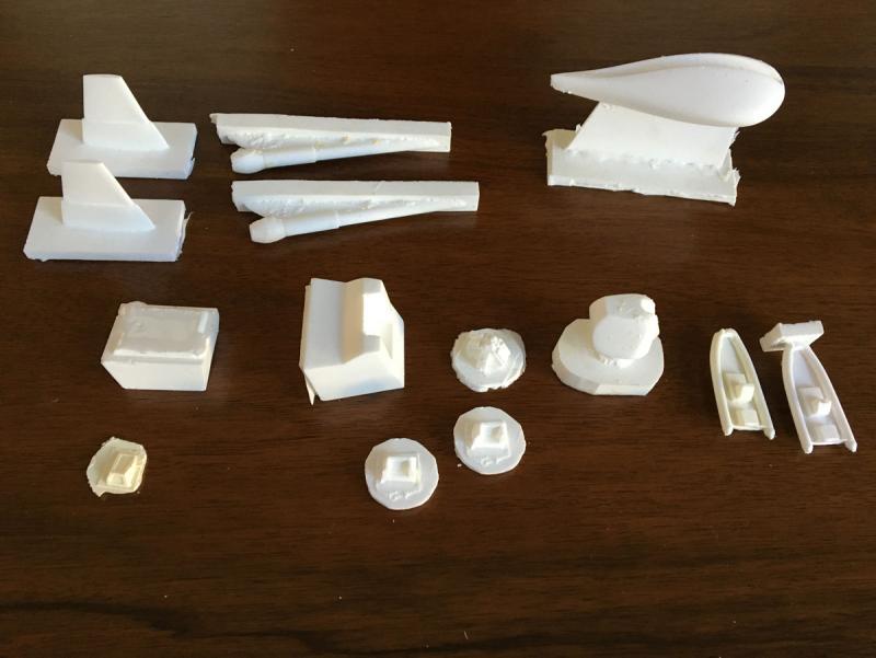
There are also a few cast resin parts. These don't look so great. I will be doing a lot of cleanup on them.

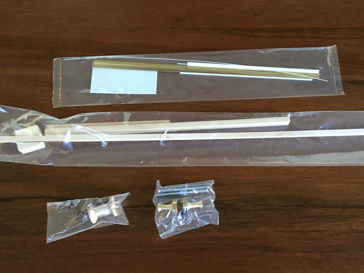
There is a small bag of wood strips, a bag of metal strips, and a spool of rigging thread. The brass pedestals were extra. You'd think that for what this kit cost they could throw in the pedestals.
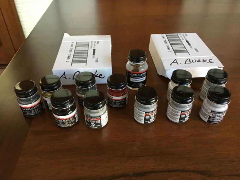
I also ordered the optional paint kit. It came with a dozen bottles of Testors paints. I will probably spray most of the model gray and use the red and black for details. We'll see.
- FriedClams, ccoyle, justsayrow and 14 others
-
17
-
Summary
Amati's kit of U-Boat 47 is an interesting build. It is a lot more complicated than a plastic model but a lot easier than a wooden model. The photo-etched brass parts are beautifully made, but the resin parts are disappointing. They have almost no detail and they don't quite fit to the brass parts. I really wish that the hull had a little detail molded into it.
Like a plastic model, this kit doesn't offer much chance to build anything from scratch. The stand is the only thing I can point to and say "I made that out of a piece of wood." The model is also less visually interesting than any of my other models. There just isn't much to see on the outside of a sub.
Finally, it only took 35 days to build this model. Winter isn't half over and I don't have anything to work on!
-
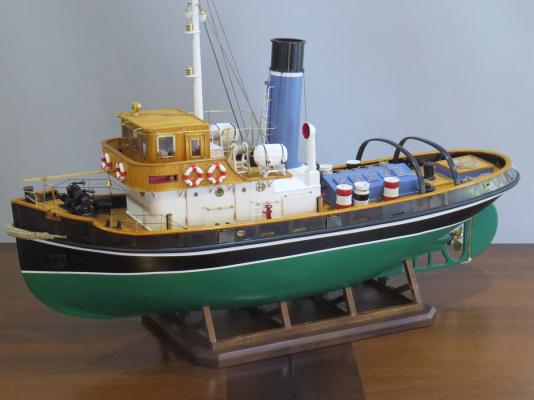
Model Complete - 80 hours, 35 days
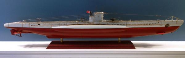
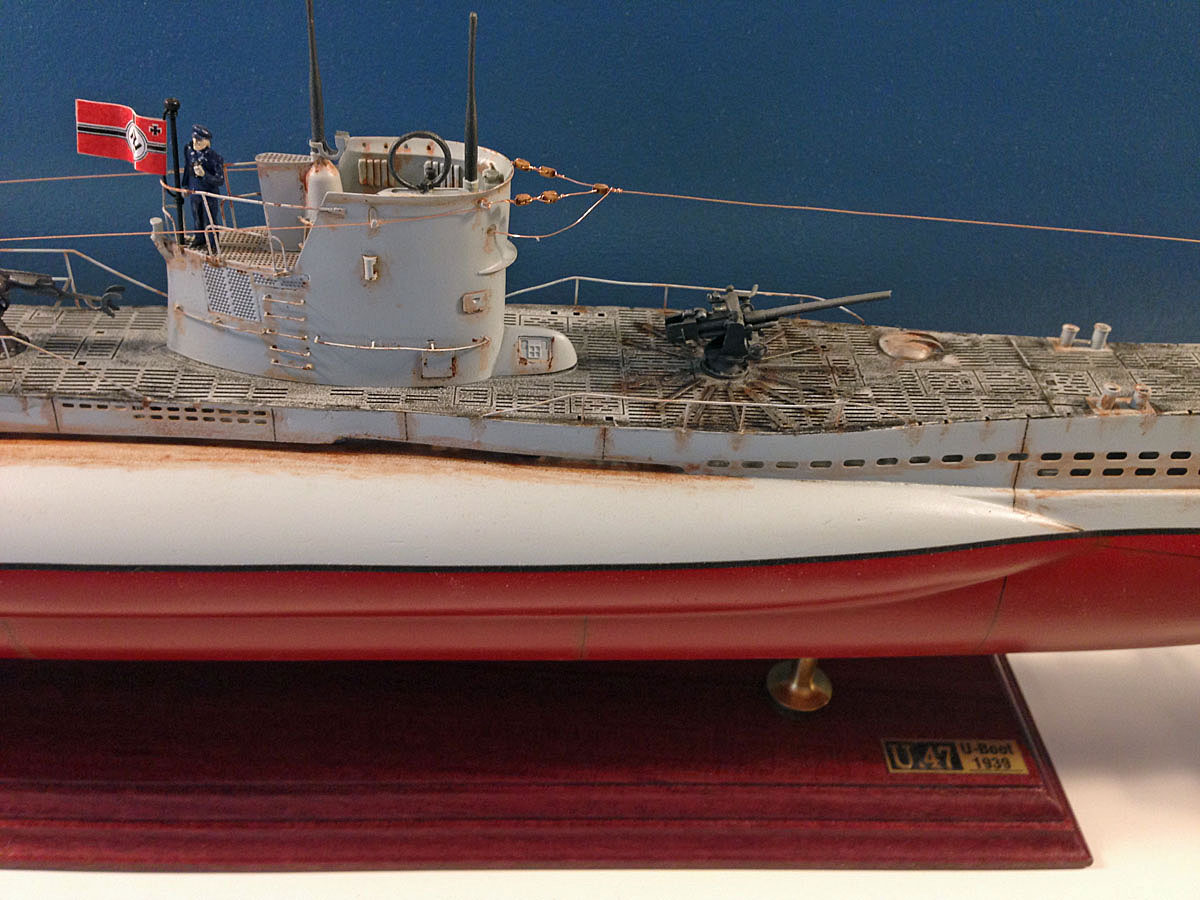
The top of the hull was painted with Krylon Fusion light gray spray and the bottom with Rustoleum colonial red. Seam lines were drawn with a 1/2 mm black Faber-Castell artist's pen.
The deck is supposed to look like gray, weathered wood so I put a very thin coat of Testors' flat black over the gray. I'm not crazy about it. I used a very thin wash of Testor's "rust" color for, what else, rust. The first try was far too conspicuous so I sanded everything lightly with 3M 220-grit foam sanding pads. I put a couple of coats of Krylon acrylic matte finish over everything. The weathering still feels totally overdone. This was the first time I ever tried to produce a weathered look on a model, and I have a lot to learn.

It as fun attaching the antennas over the deck - almost like rigging a sailing ship! And I really like the stand. I made it out of purpleheart wood that looks great with the deep red hull.
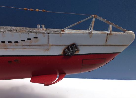
The only hint of the forward torpedo tubes are some panel lines that I drew. There plans show a large array of holes in the bottom of the hull (not visible here.) I couldn't figure out how to draw a neat array of holes so I just painted the area black.

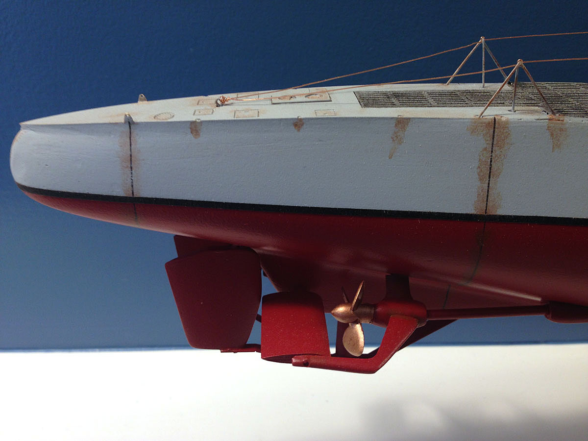
The props, rudders, and aft diving planes are a little more interesting than the rest of the ship.
-
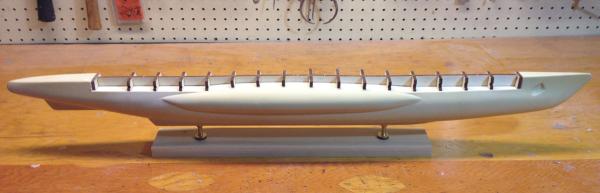
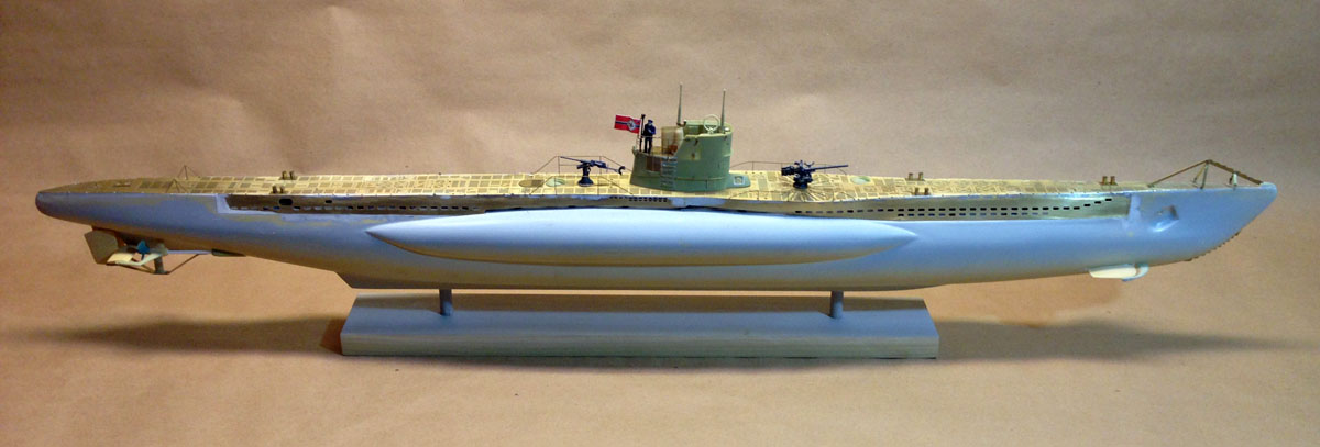
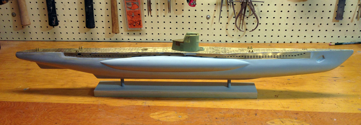
Ready for Paint - 50 hours, 25 days
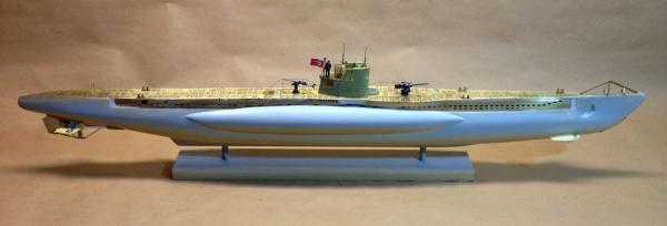
I have completed construction of U-Boat 47 and am ready to start painting. The sailor, flag, and guns are complete but unattached. The conning tower and periscope are also unattached.
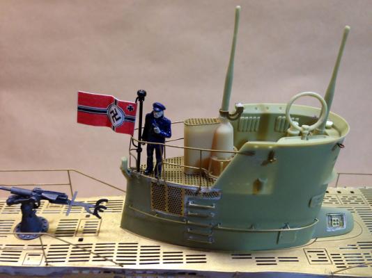
I love the sailor in the conning tower with his tiny binoculars. Moments after I took this photo I breathed too hard and the little loop antenna broke off at it's weak resin attachment point.
 I drilled it out and reattached it with a tiny brass pin.
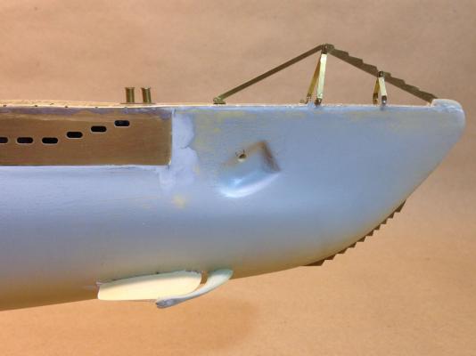
I think that the brass saw teeth on the bow must be for ice cutting, but what do I know about submarines?
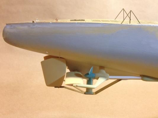
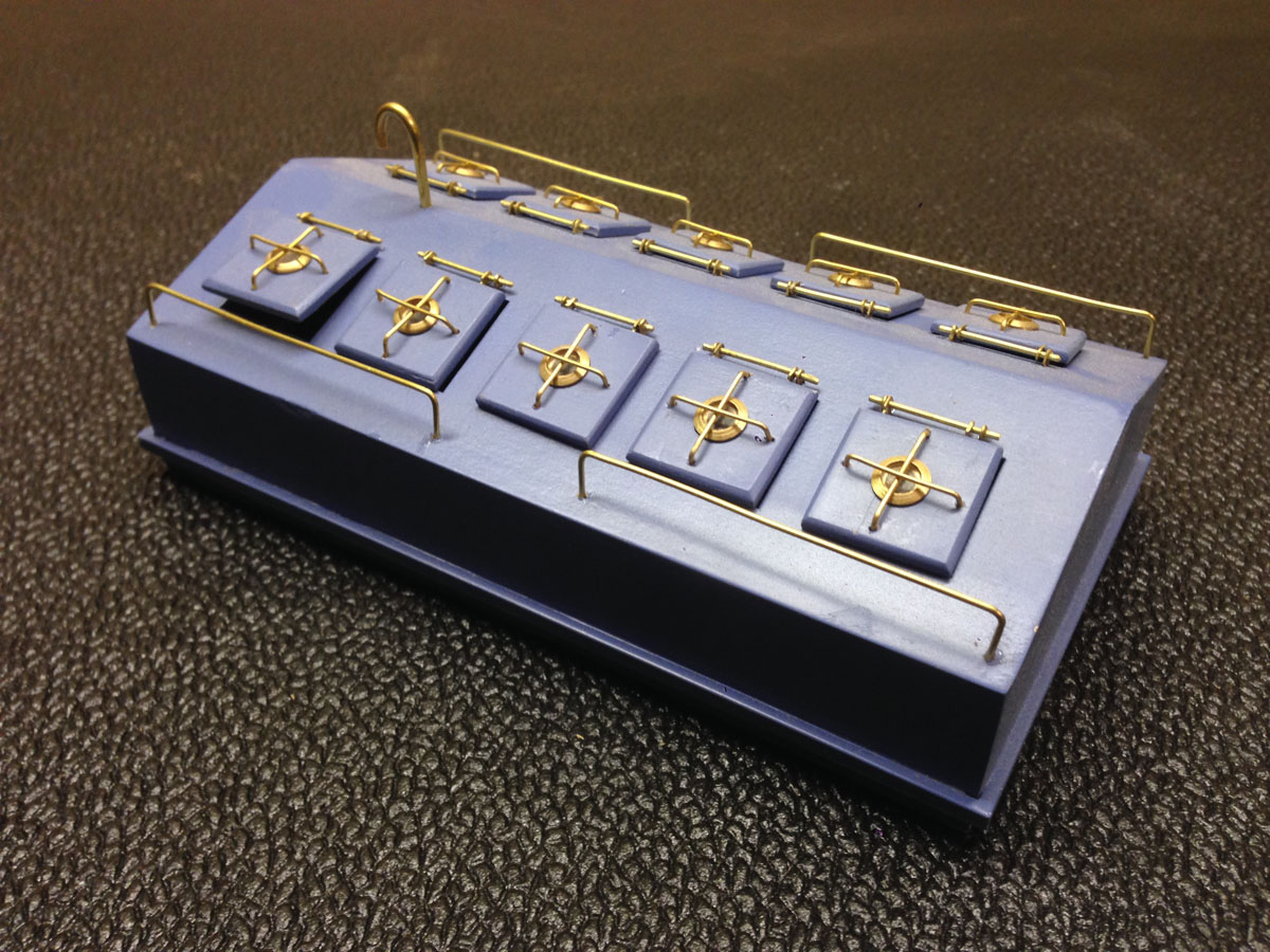
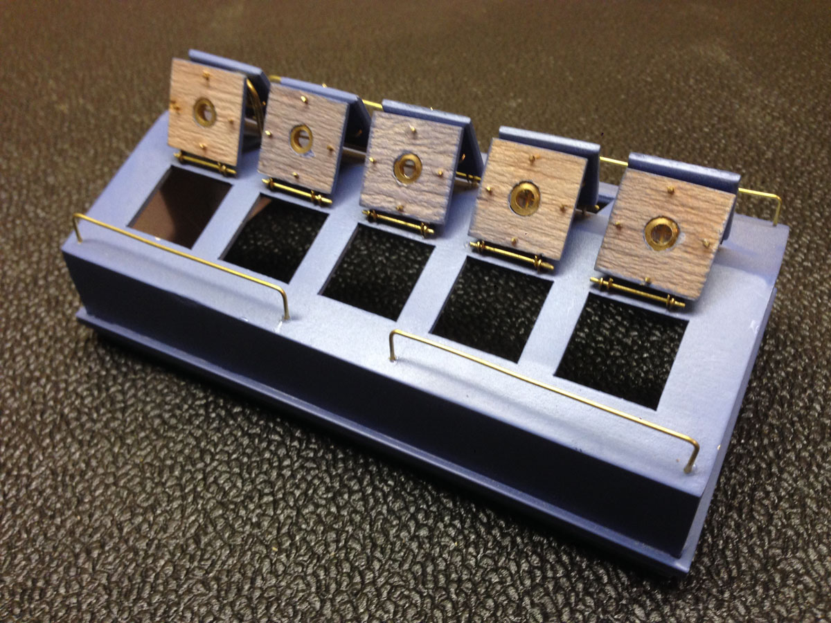
The props and rudders are made of several different materials. The props are polystyrene and had embedded nuts, probably for some other model because there's nothing here to attach them to. The other green parts are soft resin. The tan parts are also resin but are stronger and much better made. The drive shafts are polystyrene tubes. There is one photo-etched brass brace on the bottom. The only instructions are an exploded view on the large plans, and there are no holes or registration marks for alignment. However, once you locate any one piece, everything else pretty much falls into place.
It's about 10 degrees F (-12 C) here. I have to wear a jacket to paint in my unheated basement. I hope the paint doesn't freeze!
-
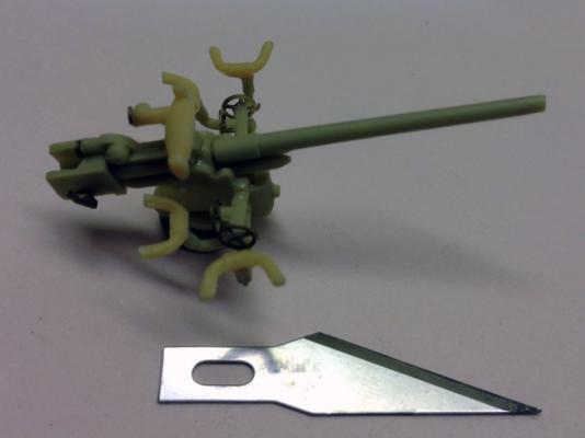
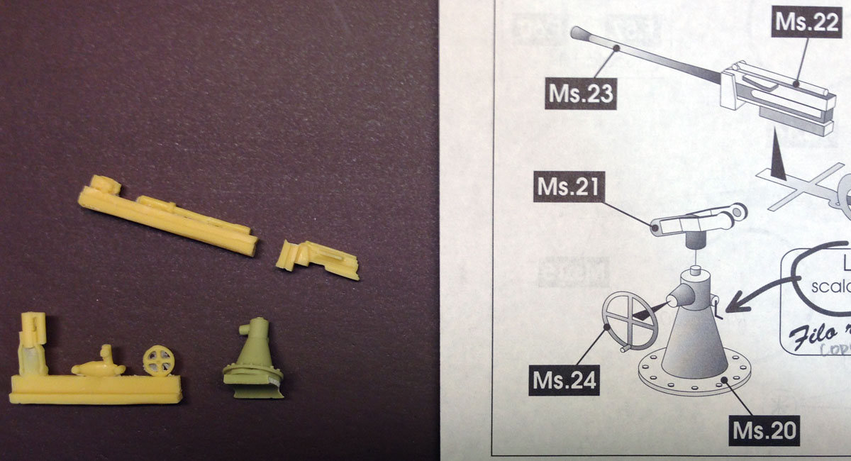
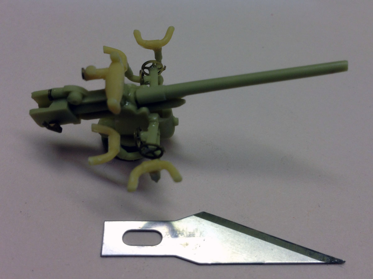
Resin Parts
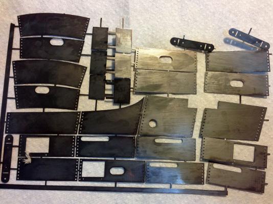
Yes, the resin parts may have shrunken. But in my opinion they aren't very well made for a kit as costly as this. I would expect to see parts comparable to a good plastic model.
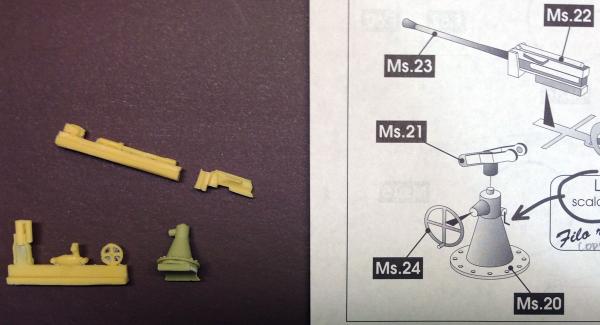
Here's a photo of the plans and resin parts for the aft gun. The resin parts have huge pieces of excess plastic that have to be removed. The scrap is often much larger than the part itself.
Conning Tower and Forward Gun - 33 hours over 15 days
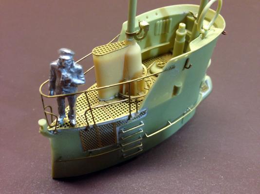
The conning tower came out nice, and the supplied sailor is a nice touch. Those brass rails were really hard to attach since, again, the holes in the resin didn't quite match the brass parts. The curved rail around the sailor is a single photo-etched part with 13 loose ends that had to be glued in place. I was almost afraid to breathe while I was working with it.
The forward gun has an unbelievable number of tiny resin parts that are all butt-joined with CA. It went together OK but it seems terribly delicate.
I'll paint the conning tower and guns separately and attach them at the last minute.
-
A Question About Weathering
The photo of the completed model on the box shows rust surrounding every joint and opening on the deck. I've been Googling articles on how to paint a weathered finish and have seen two promising techniques.
1. Use artists' pastels ground to a powder and applied with a brush, followed with a matte finish.
2. Use a dry brushing technique where rust-colored paint is applied sparingly with a nearly-dry brush.
Can anyone recommend other techniques or tutorials for making a weathered finish?
-
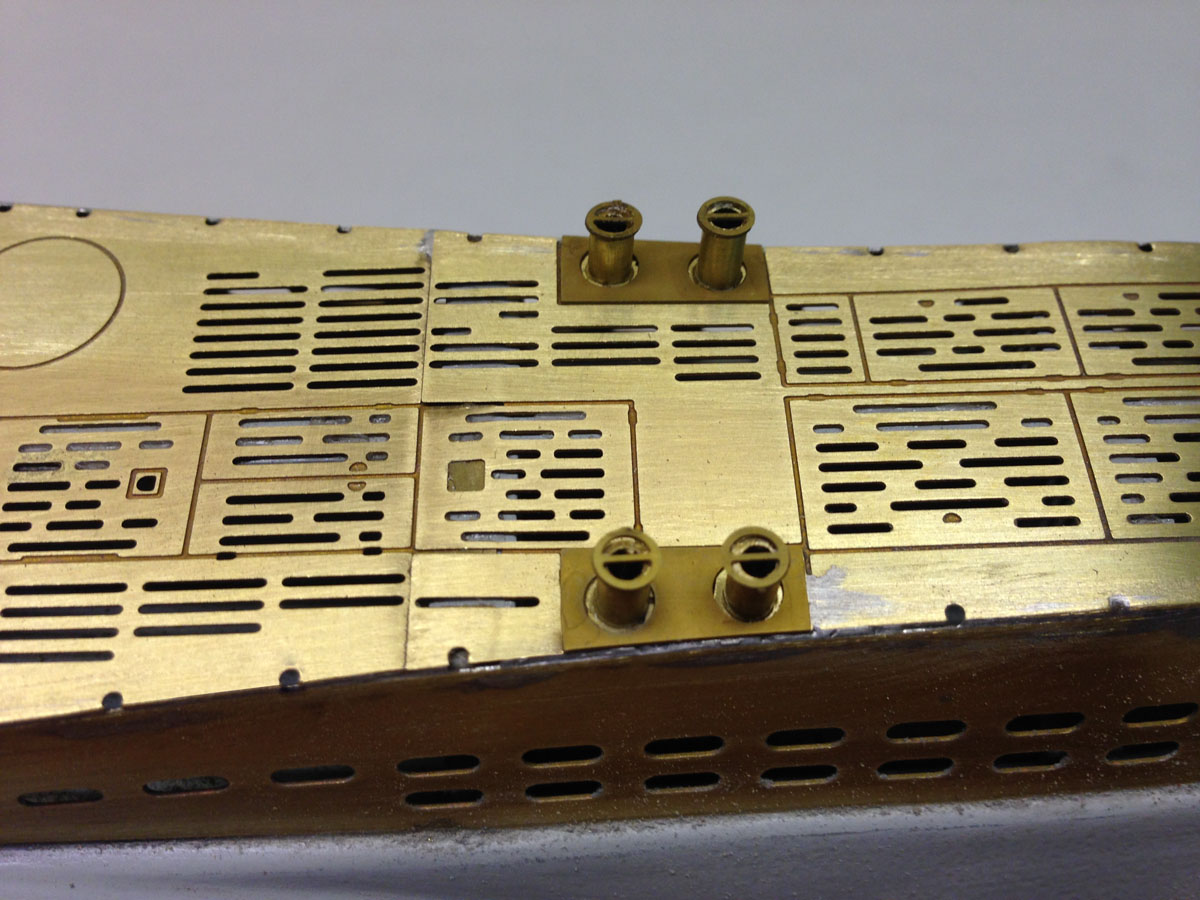
Lots of Brass Parts, 20 hours over 11 days
I repainted the superstructure gray since the brass deck is full of holes and the gray paint will get inside anyway. Then I glued all the photo-etched brass decking to the wooden superstructure using CA. I soldered the joints between the vertical sides and the horizontal deck.

I thought I was pretty good at soldering until I tried to join these edges. No matter how much I cleaned and fluxed the joints the solder just wouldn't go where I wanted it to. I ended up grinding and sanding off lots of surplus. I still have a little work to do with putty. Useful Italian word: "Stucco = putty."
Surprisingly, the kit did not include the brass tube for the cleats.
The photo-etched parts have beautiful detail.
The conning tower is resin with lots of little brass parts. Unfortunately the brass deck did not fit into the tower and the ladder rungs were wider than the holes in the tower, so I had to do a bit shaping and drilling.
- Mirabell61 and mtaylor
-
2
-
Lots of Brass Parts, 20 hours over 11 days
I repainted the superstructure gray since the brass deck is full of holes and the gray paint will get inside anyway. Then I glued all the photo-etched brass decking to the wooden superstructure using CA. I soldered the joints between the vertical sides and the horizontal deck.
I thought I was pretty good at soldering until I tried to join these edges. No matter how much I cleaned and fluxed the joints the solder just wouldn't go where I wanted it to. I ended up grinding and sanding off lots of surplus. I still have a little work to do with putty. Useful Italian word: "Stucco = putty."
Surprisingly, the kit did not include the brass tube for the cleats.
The photo-etched parts have beautiful detail.
The conning tower is resin with lots of little brass parts. Unfortunately the brass deck did not fit into the tower and the ladder rungs were wider than the holes in the tower, so I had to do a bit shaping and drilling.
-
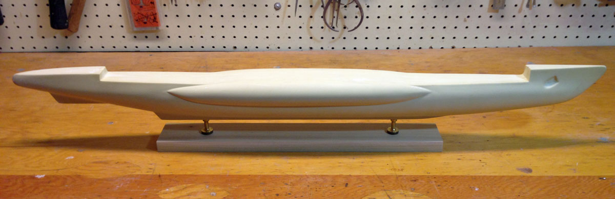
A Little Progress, 7 hours over 7 days
I started by making a temporary stand from poplar. The kit came with nice brass pedestals. I found some bolts that fit them, drilled holes in the hull and epoxied nuts in place.
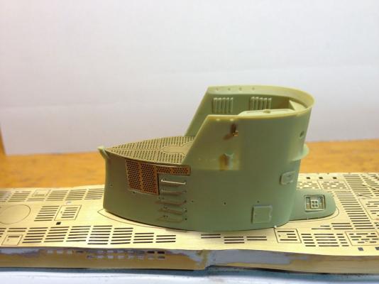
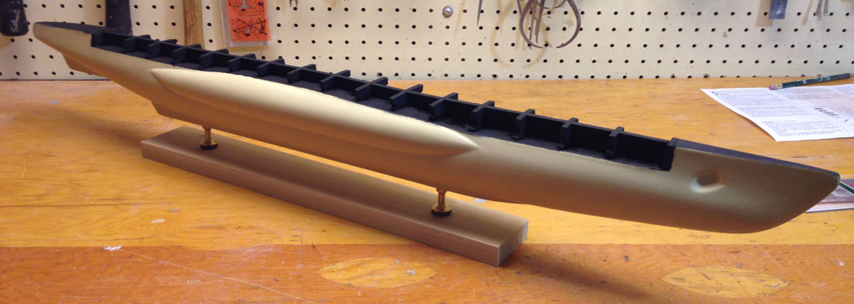
The laser-cut parts for the superstructure popped right out of the surrounding wood, but they didn't quite fit in the space atop the resin hull. I had to do some cutting and sanding to make them fit. The resin hull seems solid but it sands like Styrofoam and is very easy to shape.
And that is the end of the wood work on this model.

The superstructure will be covered with photo-etched parts with lots of holes, so I painted the interior black.
- joske, schooner, justsayrow and 12 others
-
15
-
Amati U-Boat 47 type VIIB
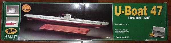
After building the Syren I didn't want any more rigging. After building the Arno XI Ferrari hydroplane I didn't want any more brass nails in the deck. After building the Anteo harbour tug I didn't want another double-planked hull. What to build next??? A submarine!
Amati offers an attractive kit of a German U-boat from 1939. You can get it for £225.00 from westbourne-model.co.uk, but I found one on eBay for much less. I've had the kit for 6 months and am finally getting started.
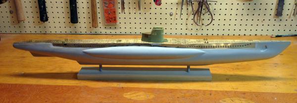
What's in the Box
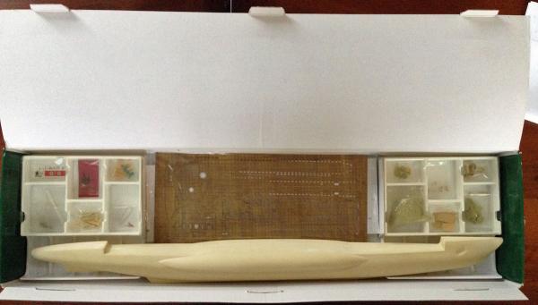
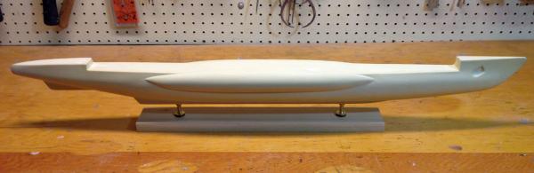
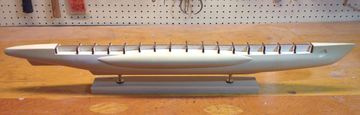
The meter long box has two divided plastic bins on the sides and one large area in the center for flat materials. The bottom contains a cast resin hull of the submarine.
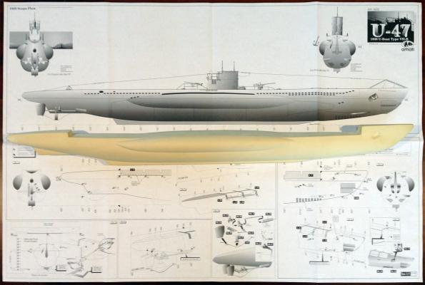
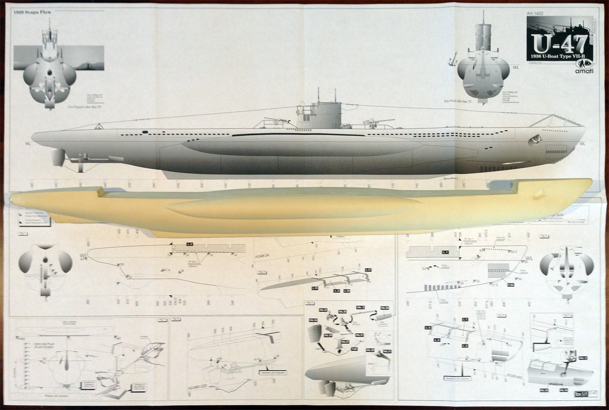
The full-sized plans are about 0.7m x 1 m, and are all in Italian. The hull seems to be two hollow pieces glued together, but I can't find obvious seams. Alas, there are no rivets, panel lines, or other details molded in the hull.
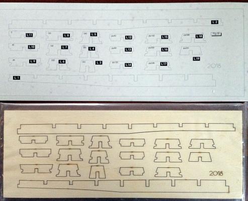
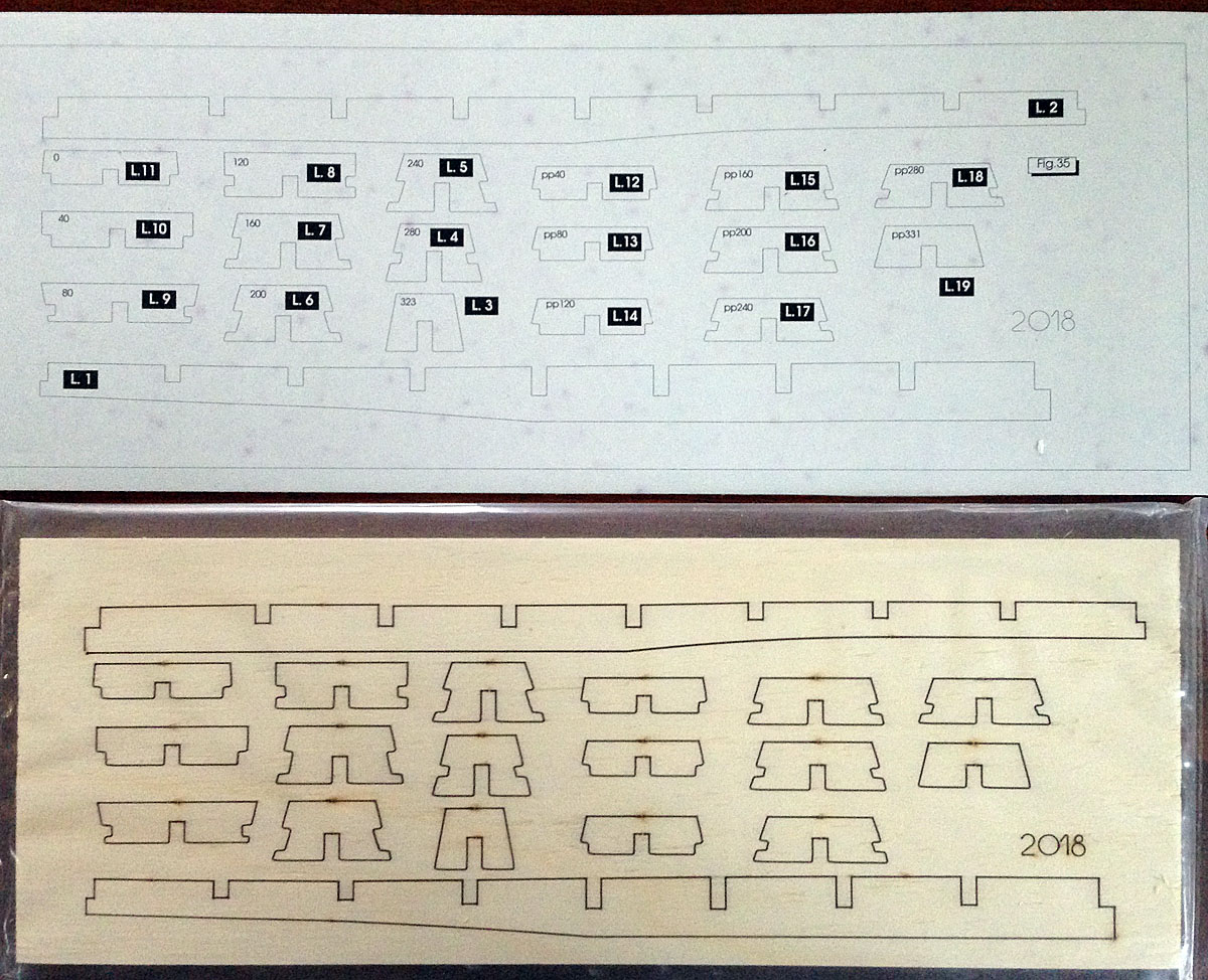
There is one sheet of laser-cut plywood parts used to build up the superstructure of the deck. There is also a heavy cardboard sheet, apparently used to identify the plywood parts.
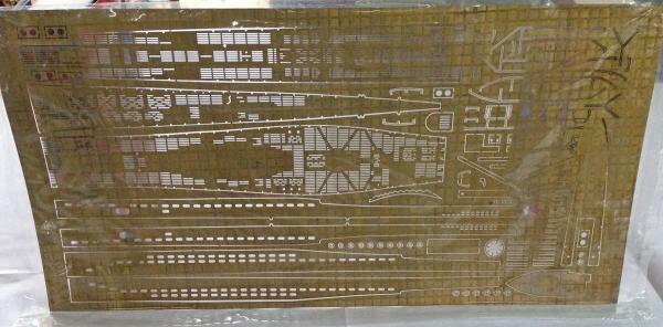
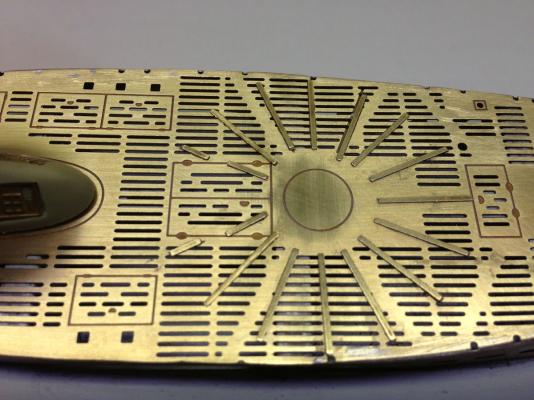
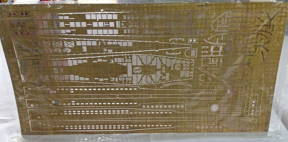
There is also a large sheet of photo-etched brass parts used to make all the of the detail on the deck. It seems to be beautifully detailed.
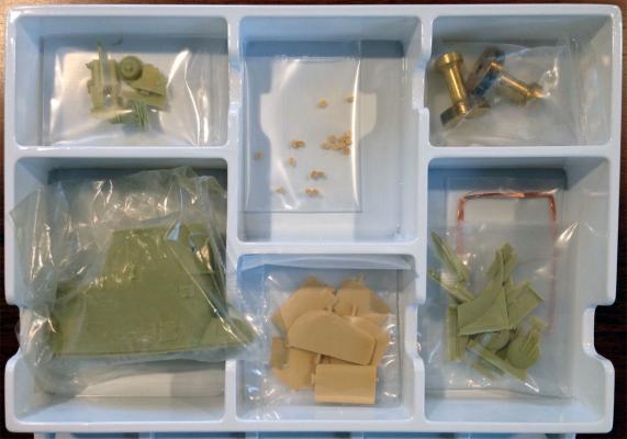
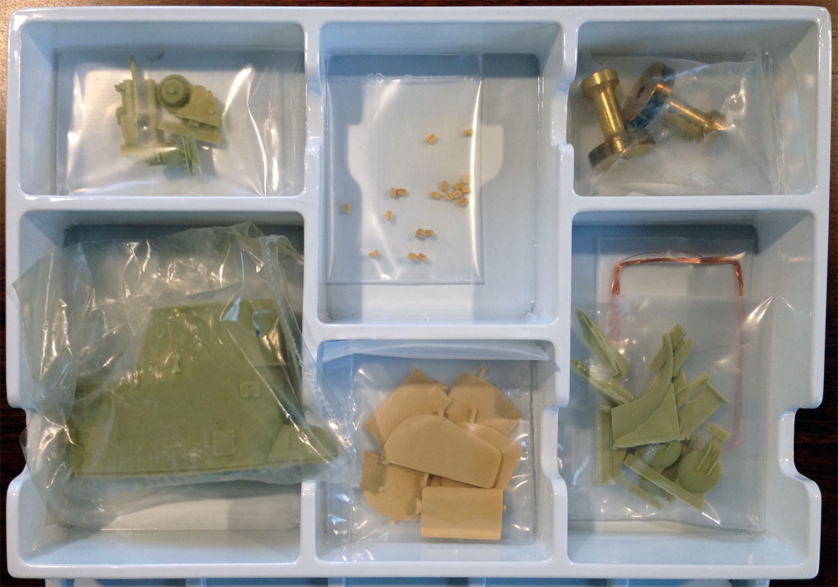
One parts bin contains a resin cast conning tower, dive planes, and some miscellaneous small parts. The kit does contain two turned brass mounting pedestals but no wood base.
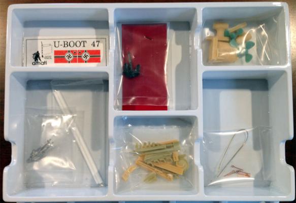
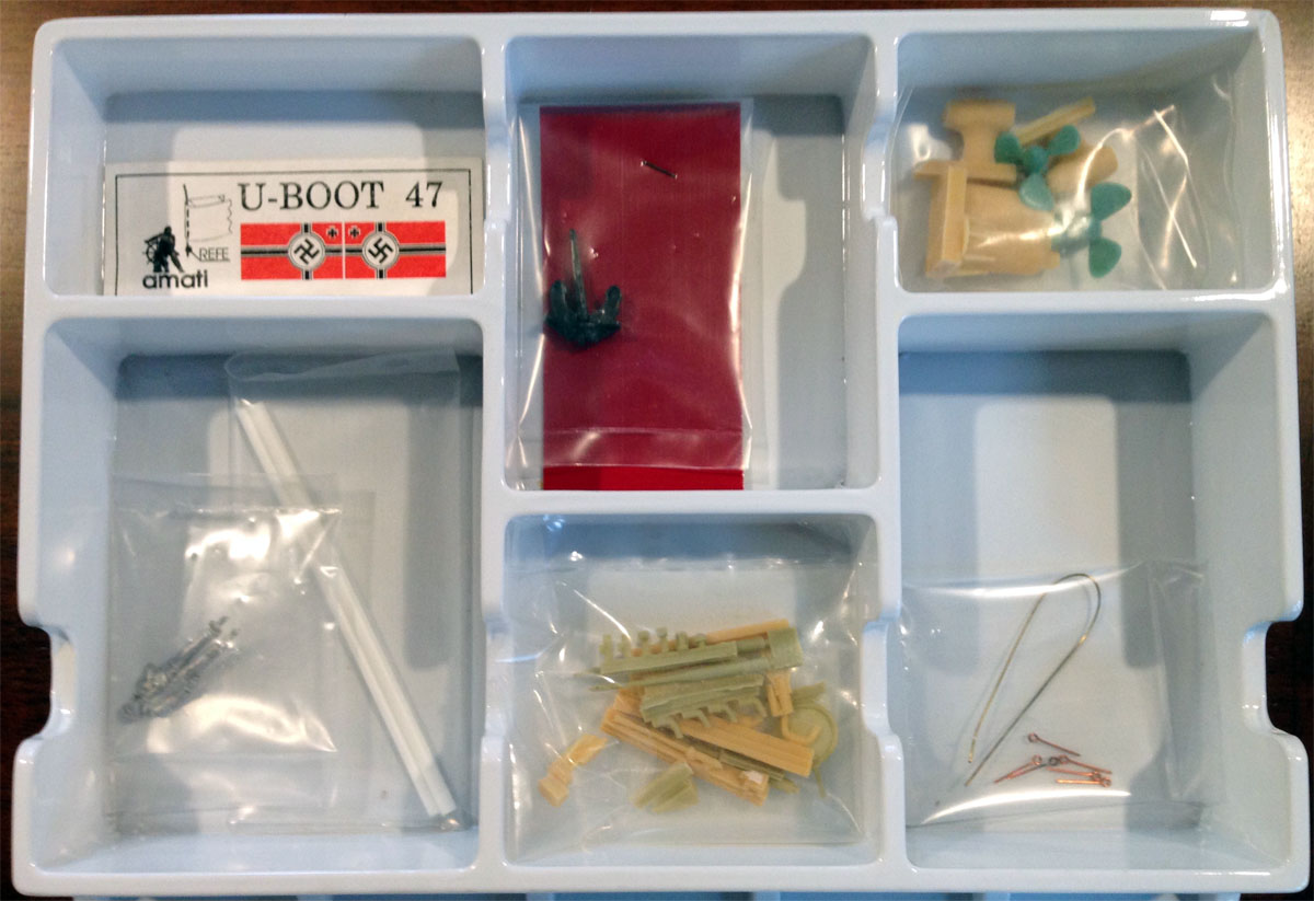
The other parts bin has a decal, and a nice cast sailor and anchor. The props and mounting hardware are, disappointingly, plastic.

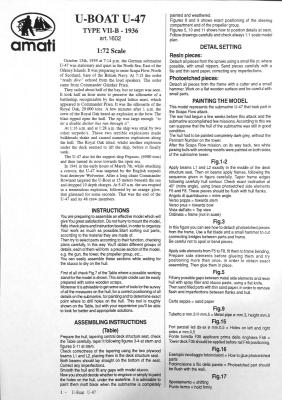
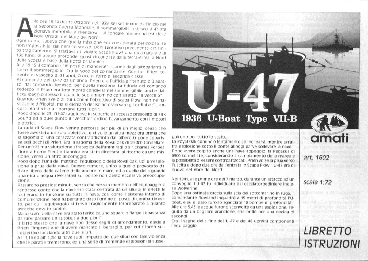
The instructions are 16 pages long and are written in Italian. But like Lego instructions they are mostly pictures, so I don't think they will be too hard to follow. The English translation is about 1.5 pages long.
I'll be starting on this after the holidays. Stay tuned for more.
- RGL, etubino, Old Collingwood and 8 others
-
11
-
Thanks Augie. I saw a completed model of the Confederacy at the Model Expo booth at a hobby show in 2012 when I bought my Syren. I'm glad now that I didn't try to start out with such a detailed model and can enjoy following your magnificent build instead.
Rod
-
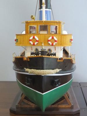
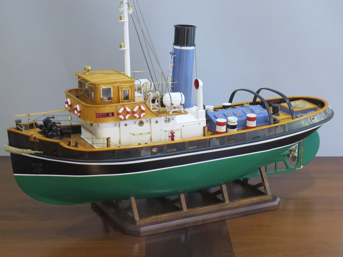
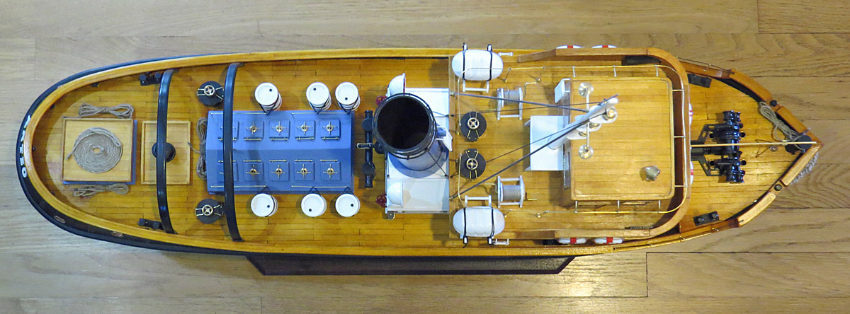
THE ANTEO SAILS!
My ANTEO harbour tug model is complete after only 205 days and 323 hours of my free time. This model was quite a bit more work than I expected, but it was worth it. I love the lines of this tug, and my long deliberations over the color scheme paid off. Now I just need a place to display it in our house.
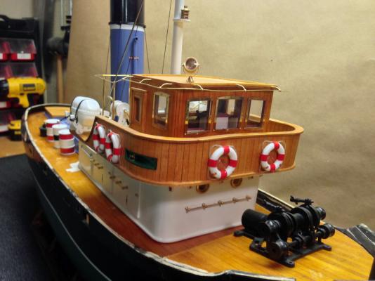
Here are some details of the model.
Two beautiful hinged bronze anchors come with the kit, but the shafts are completely hidden inside the hull.
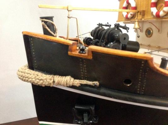
The plans show a rope bow fender on the model. There was plenty of rope but no directions were included. I Googled "How to make a rope bow fender," stayed up all night, and made my own. I think I could do better on a second try but I used all my rope. Maybe next model.
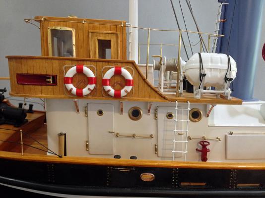
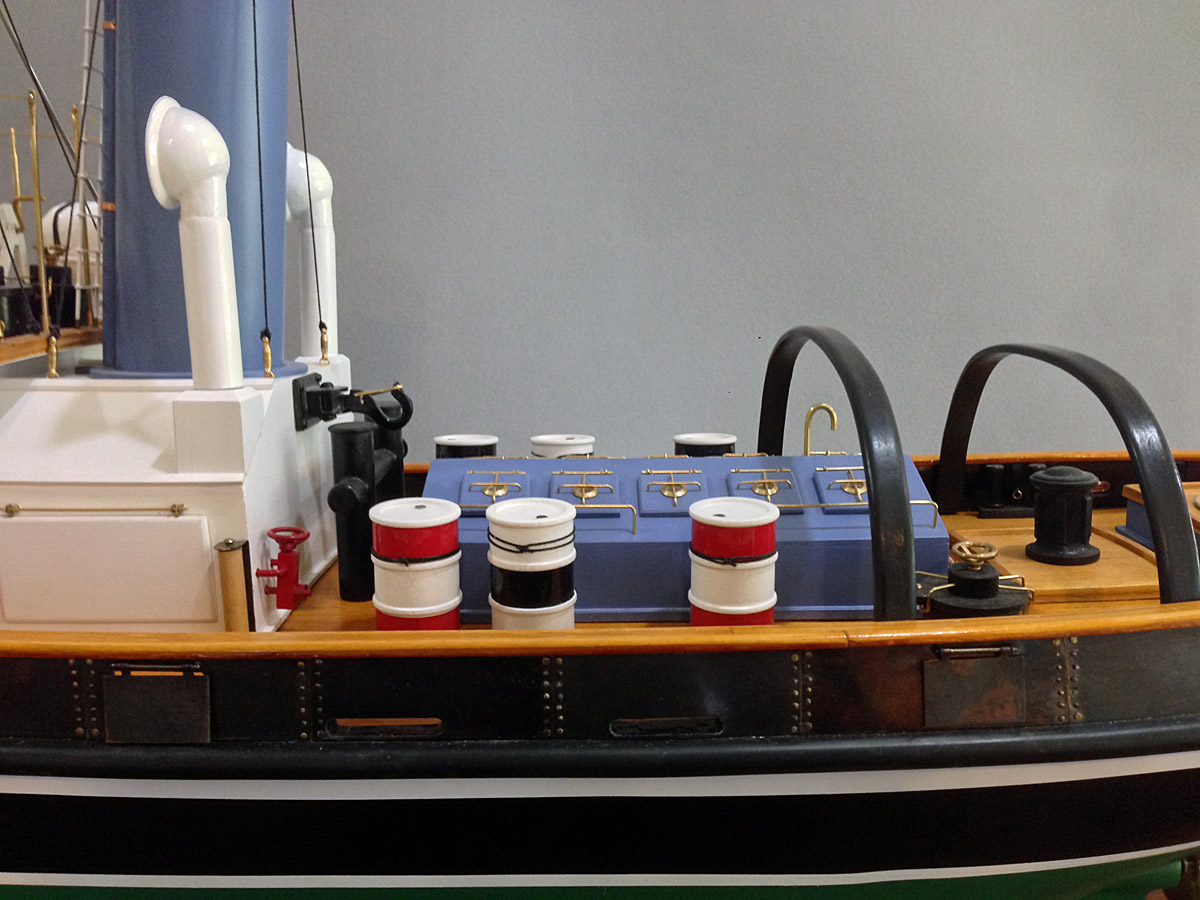
Little brass rungs were included for the ladders, but the brass wire was much too soft. I used music wire instead and glued the rungs in place with CA. The life raft canisters are hinged and will tip down, and the hand winches turn.
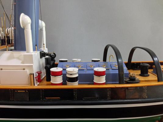
I love all the details around the engine room.
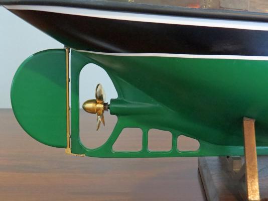
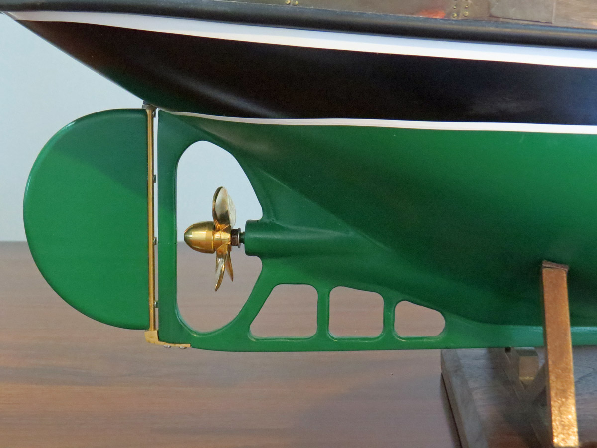
Here's the business end of the ship. The prop turns and the rudder is hinged. The plans show how to set the model up for radio control, but I would be reluctant to put this much work into the water.

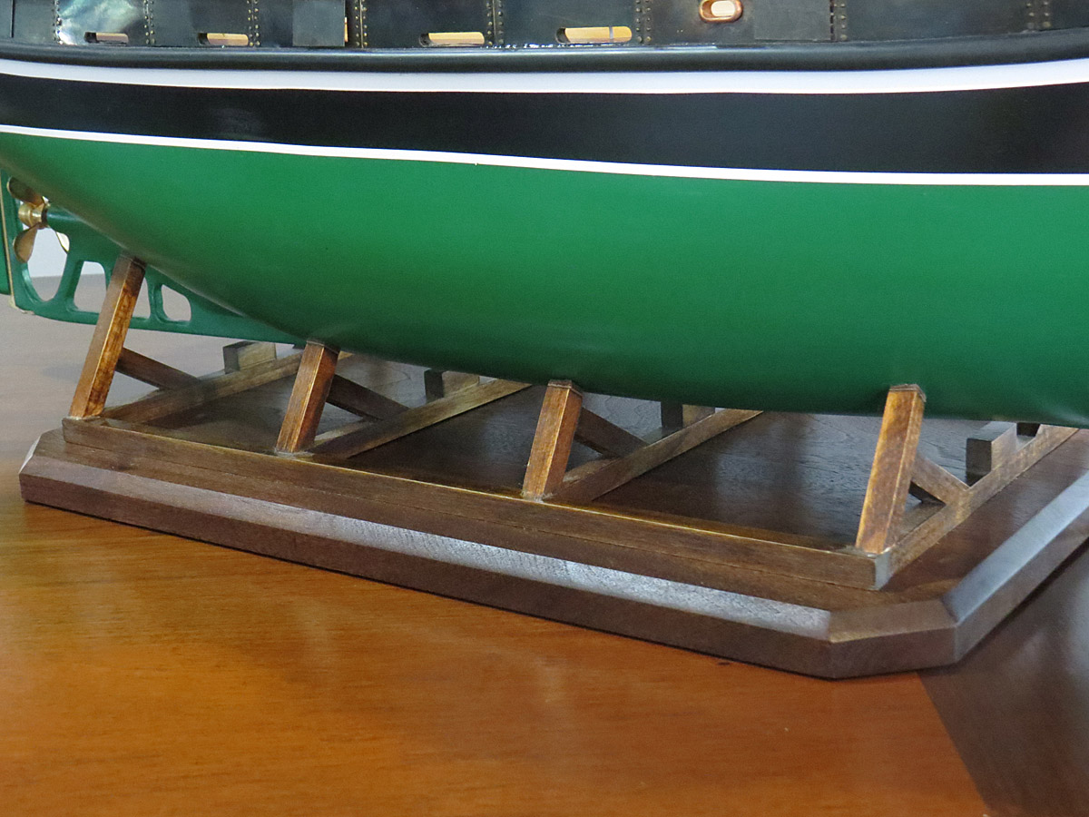
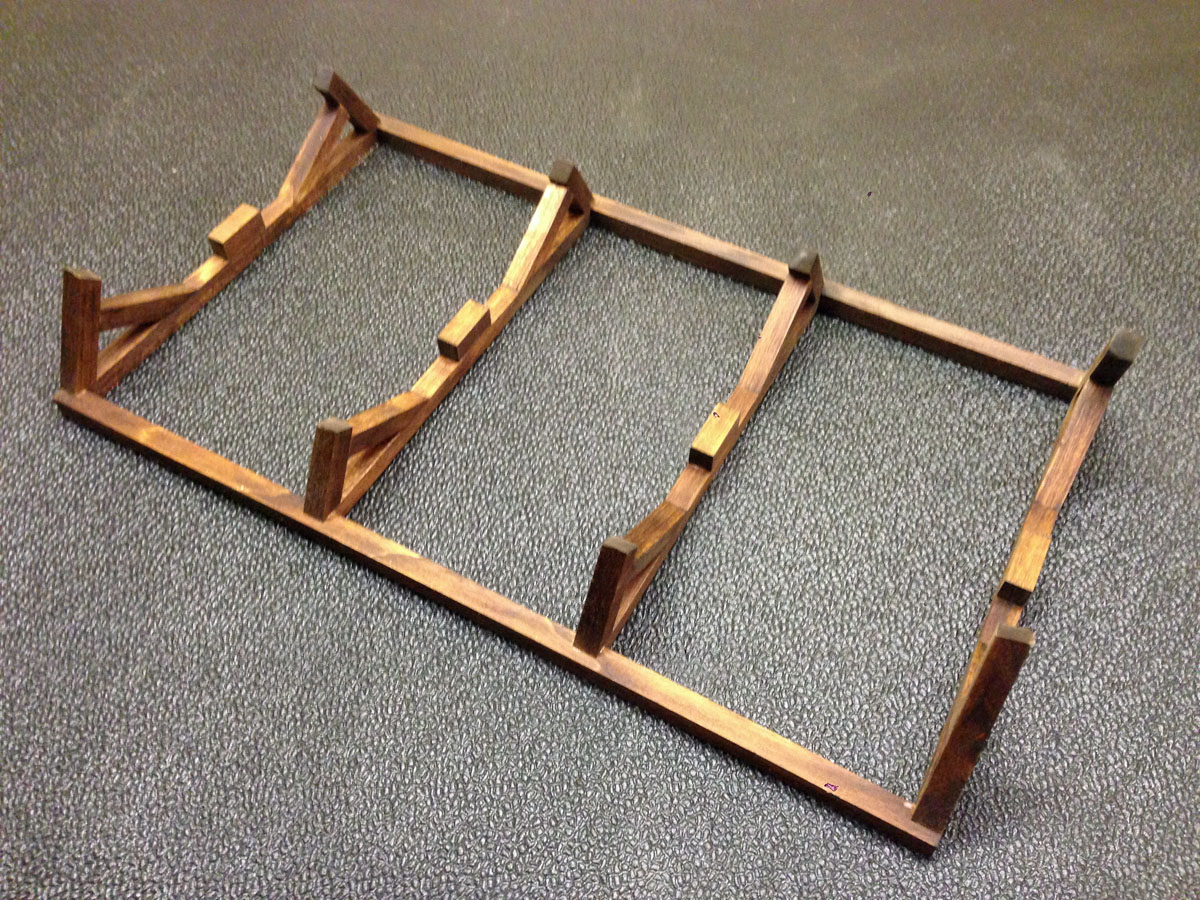
I built a walnut base to hold my basswood stand.

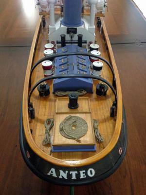
And finally, here's a gull's eye view of the ANTEO.
COMING SOON - Amati U-Boat U-47 Type VII B 1:72 Scale - STAY TUNED!
-
Hull Plates Completed
It took about 30 hours to finish the plates, cut all the ports in the bulwarks, and attach the plates with double sided tape and approximately 525 tiny brass nails. Not suitable for someone with a short attention span, but I suppose none of this is
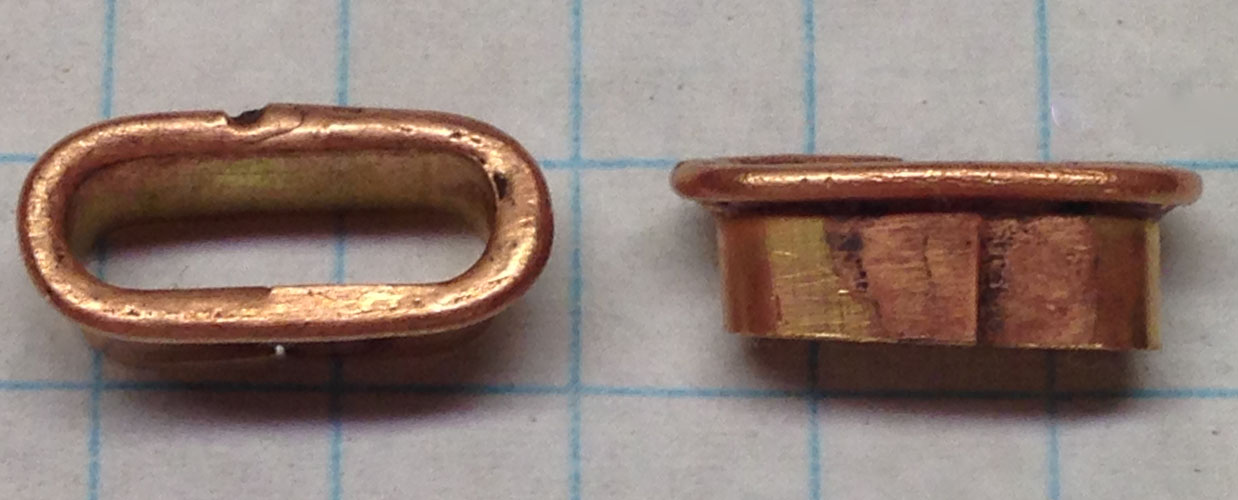
.Final Details

I finally ran into some parts that were missing from the Panart kit. There are 6 oval ports in the bulwarks that are lined with cast bronze fittings. Only 4 fittings came with my kit, so I made 2 more out of brass sheet and wire. I formed the parts around a wooden form, soldered them together, and plated them with copper patina for stained glass. They don't look too bad.
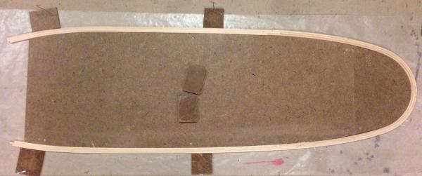
The plans show the upper rails made out of 3 mm x 8 mm basswood, with no information about how to make them fit the compound curvature of the bulwarks. I didn't have enough basswood that size left, so I bought lots of 1/8 in. square strips. I traced the outline of the bulwarks onto cardboard, subtracted 1/4 in., and traced that onto a Masonite form that I then cut and sanded. Then I steamed the basswood strips with a wallpaper steamer, bent them around the form, and glued them with CA. Pretty complicated for a railing but they came out nice.
Here's the final result showing the ports and rail. The rail and deck all have 3 coats of orange shellac. The black arches (or whatever the proper nautical term is) were also steam bent out of basswood. Cast bronze letters were provided and painted white for the ANTEO name.
-
Kurt,
Thank you for posting the photos of the Alice E and your model of her. Seeing photos of a beautiful scratch-built model like yours helps bring me back to earth when I start to feel complacent about my work on a kit
The "water inlets" on the Anteo are labeled as such on the plans, but other Italian-to-English translations in the instructions are pretty poor. Two ports are located on the main deck behind the engine room and could easily be escape hatches, but two more are located on the upper deck above what I think are crew quarters. There are several doors below so escape hatches seem unnecessary, but water tanks don't seem likely there either.
Finally, I had not heard of the nautical research guild, and just spent a couple of hours on your site. It sure looks like something that I need to join.
Rod
-
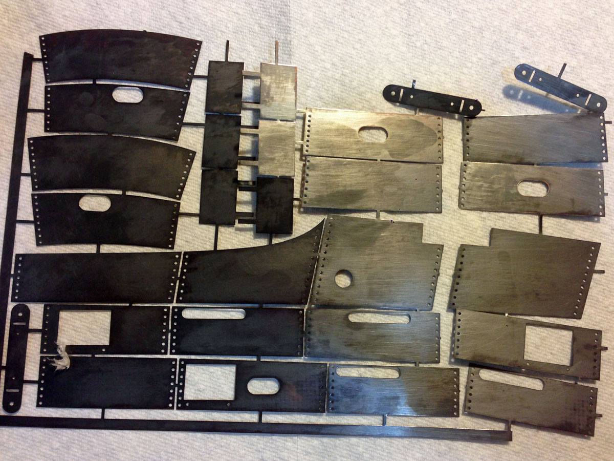
Hull Plates
The Anteo kit includes a large sheet of photo etched brass plates that surround the top of the hull. I felt that shiny brass was unrealistic around the top of of a tug, so I colored the plates black with a chemical used to patina stained glass.
The plates are a b*tch to attach. Most plates have a hole that has to be cut through a triple-planked basswood hull. No matter how carefully I drill, cut, or sand, the paint gets scratched on the outside, the wood tears out on the inside, and a tool slips and gouges my beautiful deck. It will take a bit of cleanup after the plates are all attached. The plates are attached with 3M double sided tape. That works beautifully. Each plate edge has 7 or more holes for tiny brass nails. The only problem is that the nails are too long so I have to cut them off. The blunt nails don't drive well so I have to pre-drill every hole. I'm getting about 3 plates done each night.
-
The Anteo Was Almost Launched
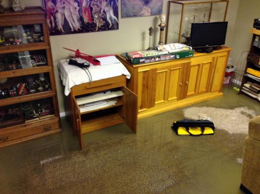
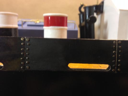
Two weeks ago my Anteo tugboat almost got launched. We had the "storm of the century" here and my basement rec room and workshop were flooded. The photo shows my rec room with my Syren model and Amati U-47 U-boat kit (future build) safely out of harms way, while my DeWalt tool bag floats by from my workshop. The ensuing chaos has kept me from posting for a while, but things are mostly back to normal and I am building again.
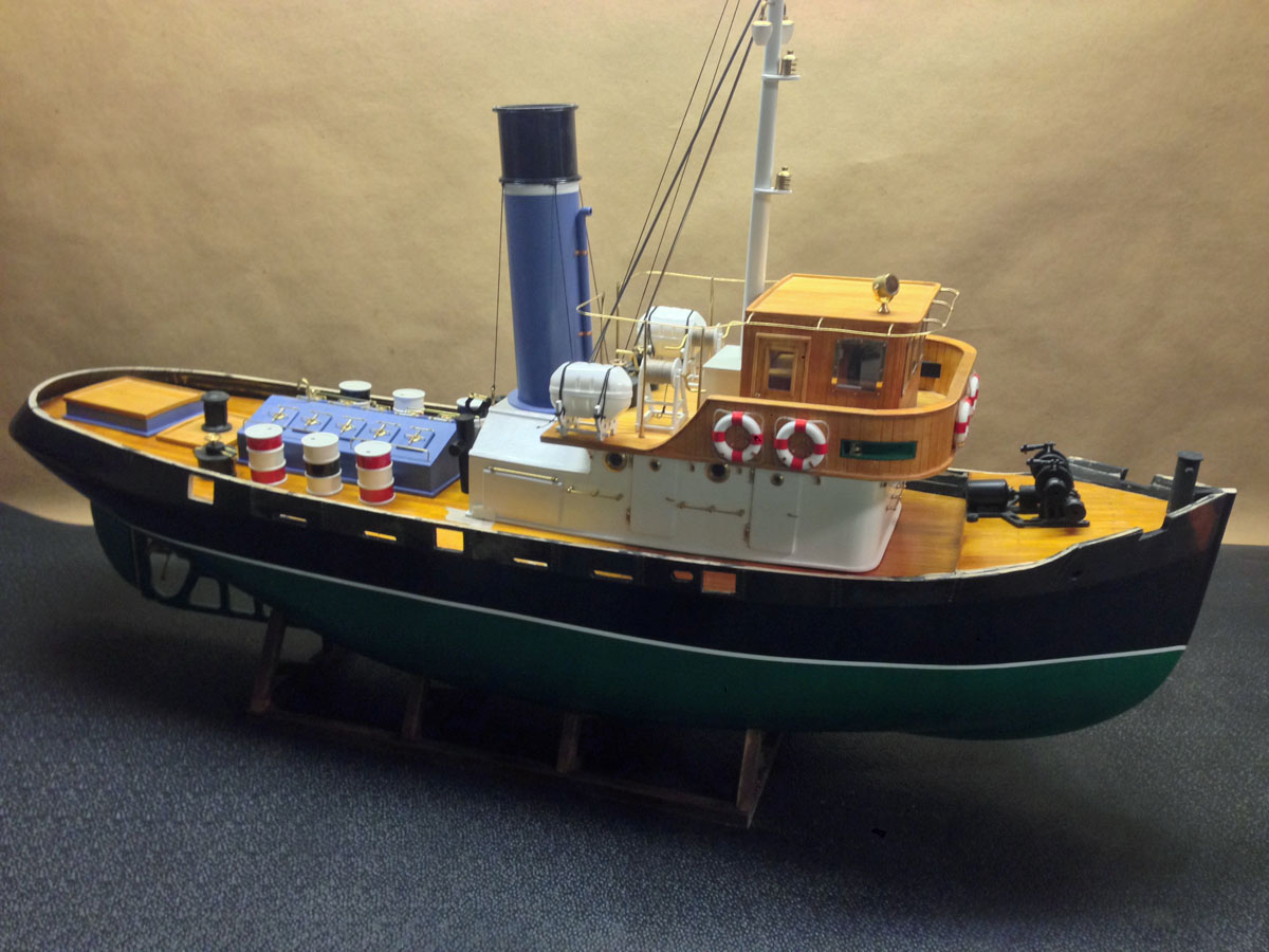
Final Paint Scheme
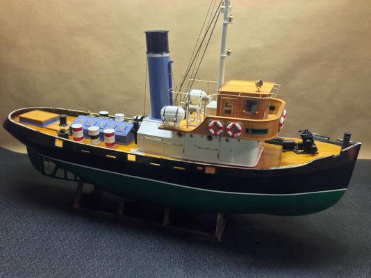
Before the flood I decided on a paint scheme: Emerald Green for the hull and Periwinkle for the trim. I love the final look.
Engine House
The engine house has 10 hinged windows. Each hinge is made with two brass "eyes" drilled into the house, a third drilled into the window, and a pin made of brass wire. Each window has a brass porthole with a clear plastic insert. I love the detail in the Panart kits!

I had planned to glue the windows shut so I didn't finish the insides, but the hinges were so cool that I had to leave them operable.
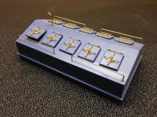
Lifeboat Containers
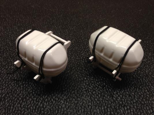
The lifeboat containers are vacuum formed plastic. They would probably be fiberglass on the real tug so I left them with their glossy white finish.
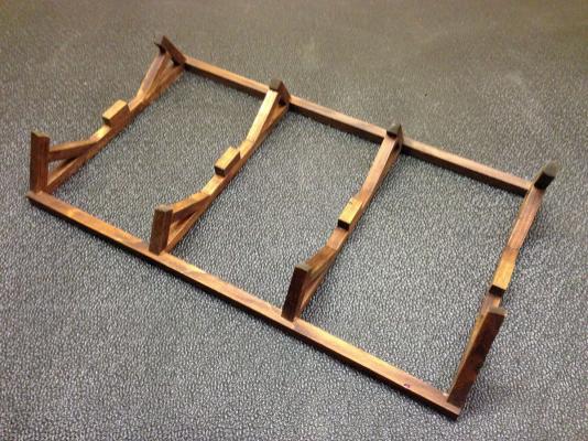
Stand
Kurt, thank you for identifying the Alice E model. It looks beautiful. I found the image in a Google image search. Do you have pictures posted on MSW? I ended up making a stand a lot like yours, but I still have to mount it on a wood base.
And the stand for the Coral Sea is awesome! There are more little details on the ground than I have on my whole boat.


USS Arleigh Burke by rvchima - FINISHED - BlueJacket Shipcrafters - 1/16" scale - guided missile destroyer
in - Kit build logs for subjects built from 1901 - Present Day
Posted
Getting Ready to Paint
No need for a fancy jig to mark the waterline. So far I've sprayed the top of the hull Haze gray, masked that off, and sprayed a coat of red on bottom. Photos coming soon.