


Stuntflyer
-
Posts
1,196 -
Joined
-
Last visited
Content Type
Profiles
Forums
Gallery
Events
Posts posted by Stuntflyer
-
-
Thank you for the comments and "Likes"
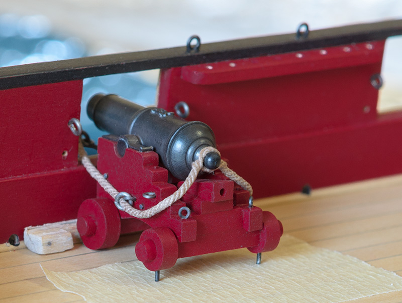
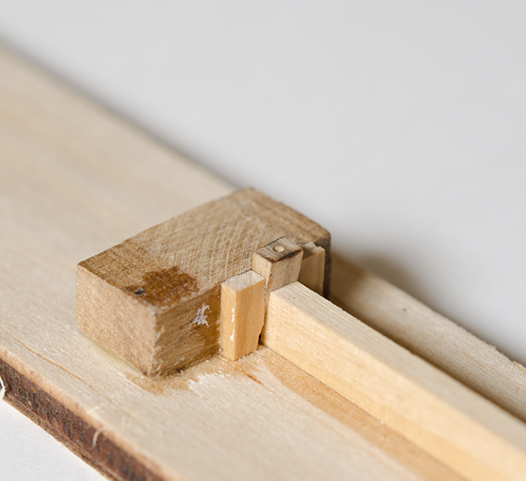
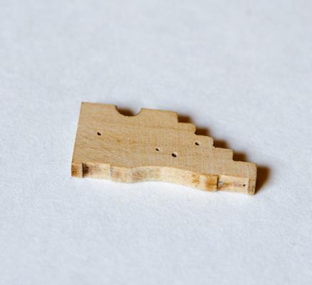
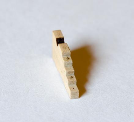
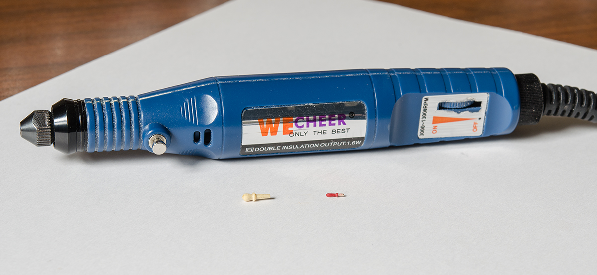
Brian - The photo below shows pretty much how I set things up. The wood spacer is 3/32" deep with a tab on each end to help keep it flat on the deck. The pins are about 1/16" long and filed flat and to equal lengths. Once the gun is aligned it's only a matter of creating the indents into the masking tape. When pressing down I found that a rocking motion (side to side) works better than just pressing straight down. The indent will be very shallow yet still visible for drilling. To allow a little wiggle room I made the holes a few thousandths oversize.
Honestly though, It's a time consuming process that one might find unnecessary. Though not shown in the previous post, I have since re-positioned the two guns at the stern that were slightly off center to the port openings. The pins were removed and they were just glued to the deck without any issues.
-
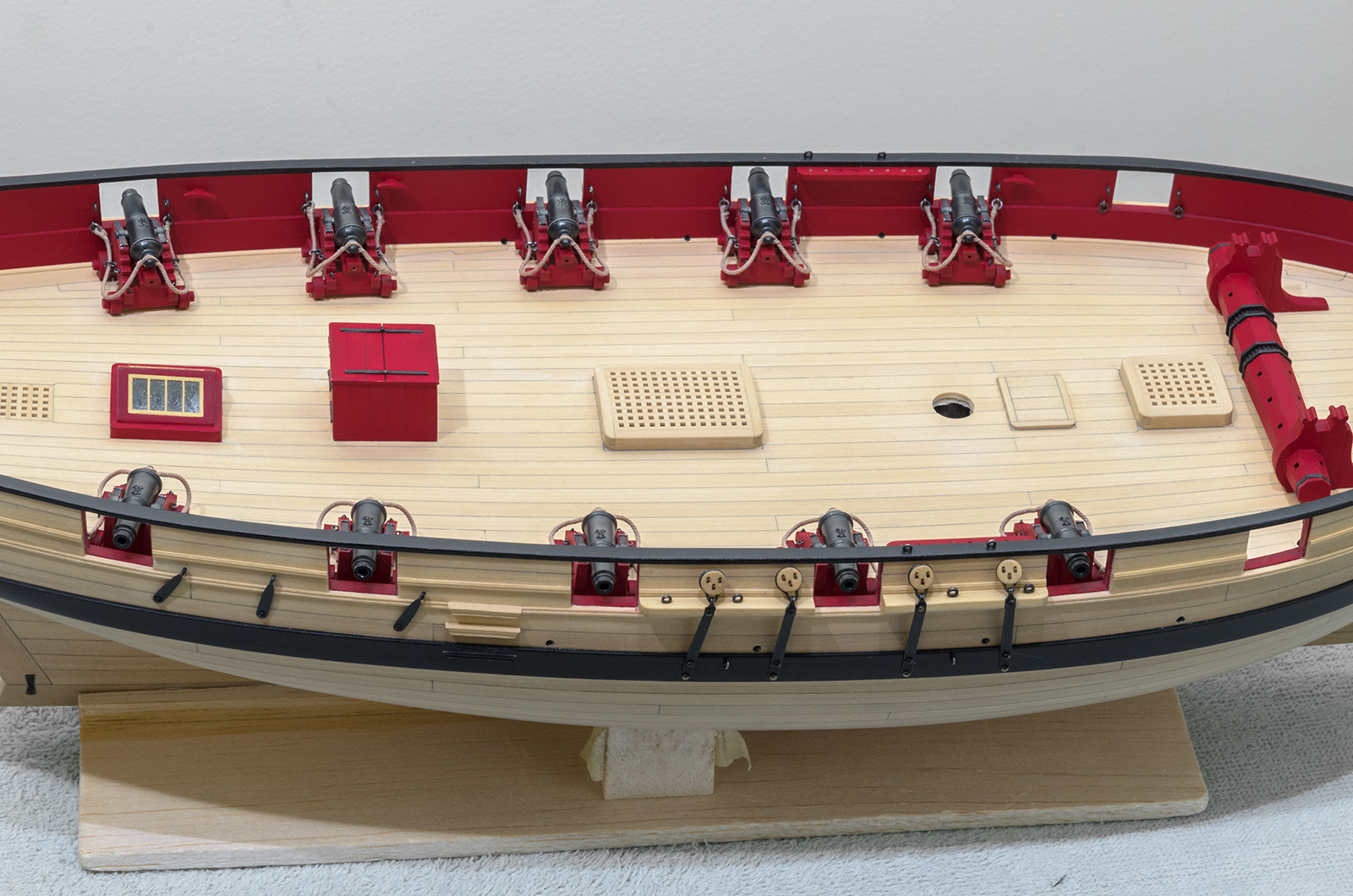
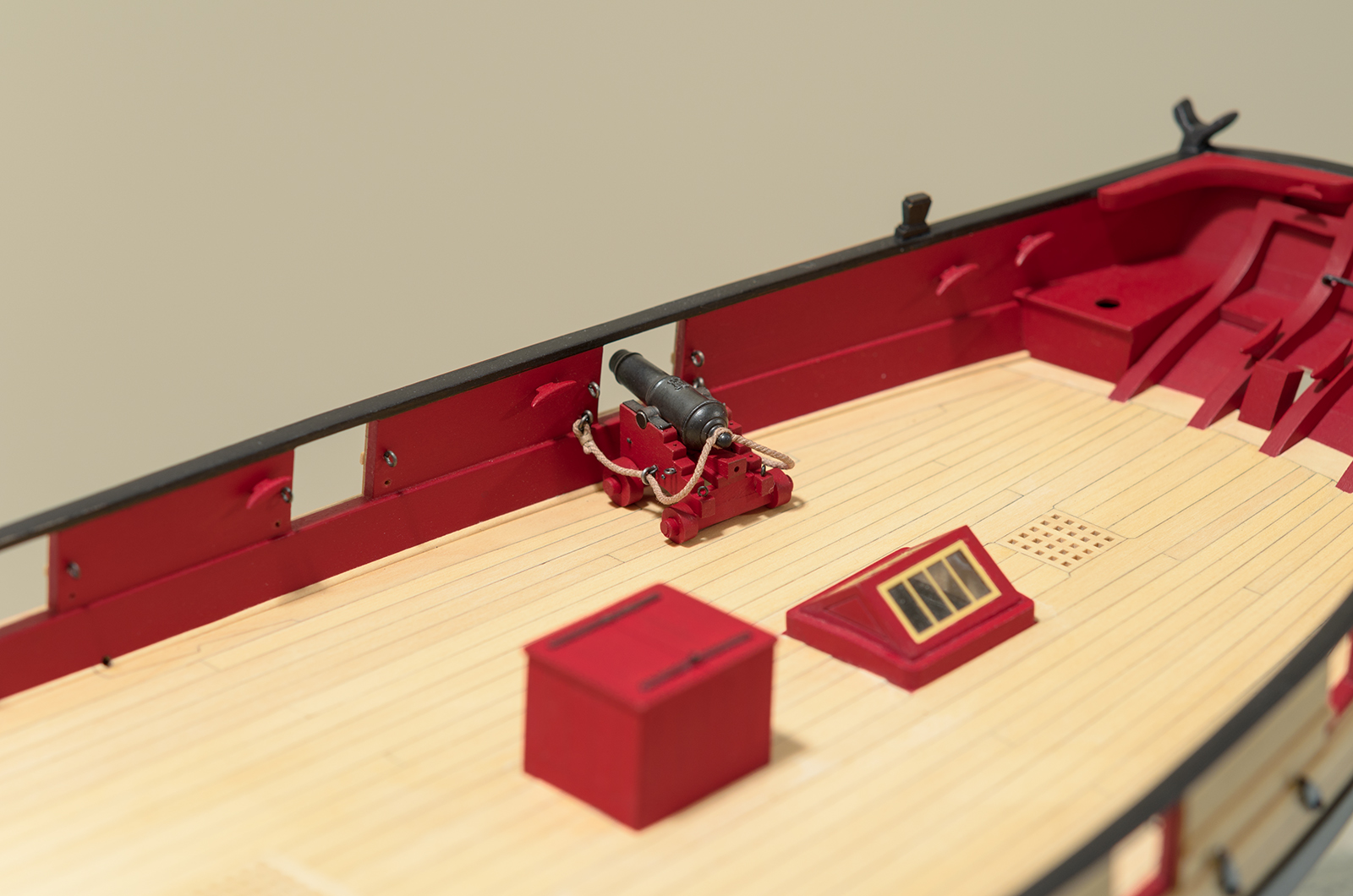
I made a little progress over the past week. Managed to get the carronades on the deck along with the breech ropes. I decided to go through the process of pinning the rear trucks to the deck with 24 gauge wire. I really took my time here for fear of making an unsightly mistake. Though not necessary to do this, the process was an interesting one and I learned a few tricks along the way.

-
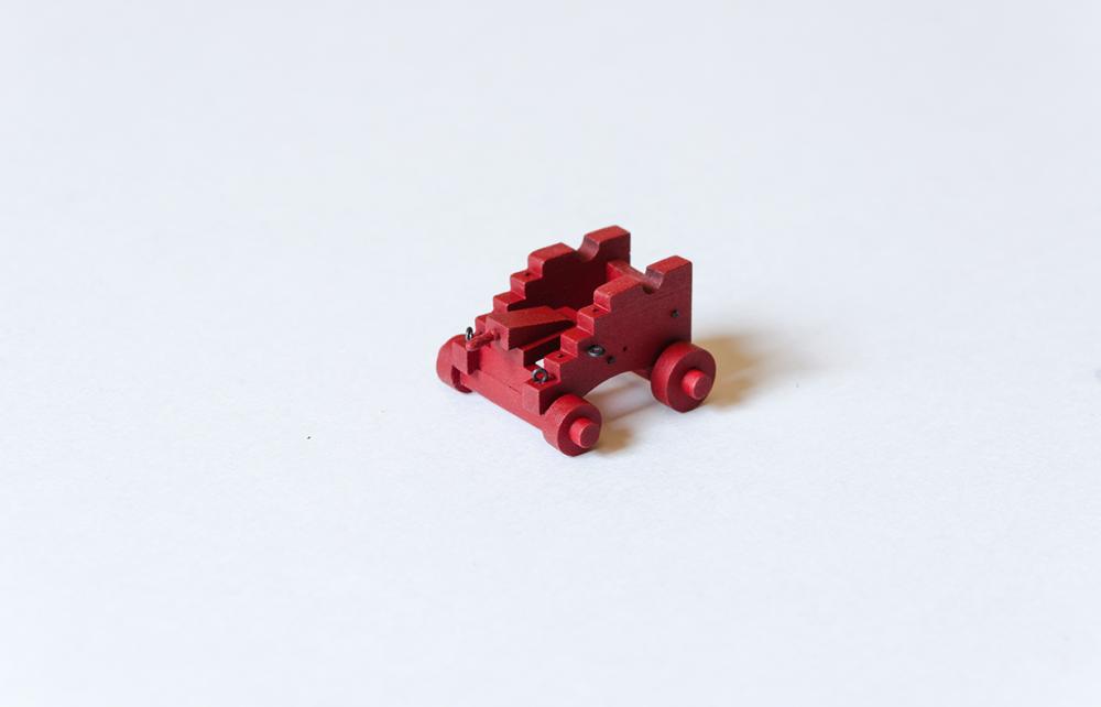
All of the parts for the carriages, guns and gun tackle are completed. I assembled the first of the carronades to see how the breech rope looks. If something is not right, please let me know before I get started on the remaining ones.
The guns where first given a spray coat of etching primer. As it is not recommended to place the paint directly to the etching primer, the guns were then sprayed with Krylon Gray primer before spraying on Badger "Model Flex" Engine Black paint. Final color was achieved using Doc O'Brien's Rusty Brown weathering powder. I deviated slightly on the capsquare simulated hinge arrangement. I used 24 gauge wire instead of 28 gauge. The wire is placed up against and behind the capsquare making for easy placement of the wire. Although slightly thicker, you really can't tell since the capsquare thickness makes it look smaller than it is. The quoin handle will go on later.

- davyboy, Ryland Craze, Dubz and 17 others
-
 20
20
-
-
-
Hi Mike,
Would bamboo be easier to draw than boxwood? Instead of brass nails maybe you could use copper. I would think that you could file the nails down if you used a #0 or #2 flat riffler without damaging the hull. http://www.ottofrei....nd-LR12711.html. Anyway, just a thought
Mike
-
-
-
Thank you Matt and Niles for your kind words and for all the "Likes". Very much appreciated!
Cheers,
Mike
- Mirabell61, Canute and mtaylor
-
3
-
Hello Matt,
Wonderful build log and a testament to your scratch building expertise. If you don't mind me asking. .What material would you use for making things like eyebolts and how would go about blackening them. Also, it appears that in post #2 you blackened the nails after they were inserted into the wood?? I have tried to blacken brass using "Blacken-it" with mixed results. Dark annealed steel wire works okay but, the color wears off easily.
Thanks,
Mike
-
-
-
-
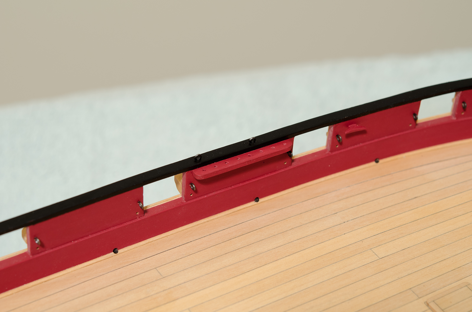
Hello everyone! While waiting for some gun paint to arrive I made the pin rails and started on the belaying pins. Earlier photos show that I used the WeCheer to hold the Quoin handles. Well, after only a few months of use it seems that there is some kind of loose connection in the wiring. I switched over to the Dremel for the belaying pins.

-
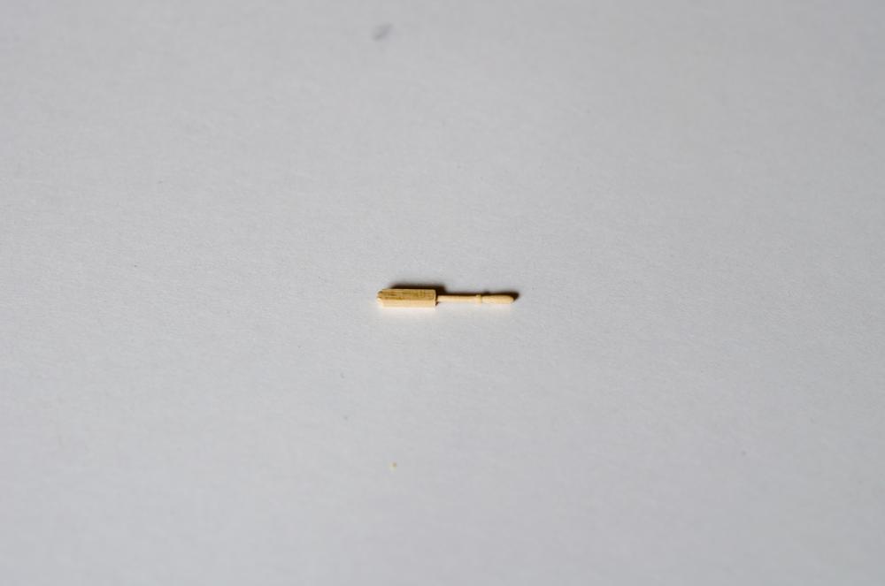
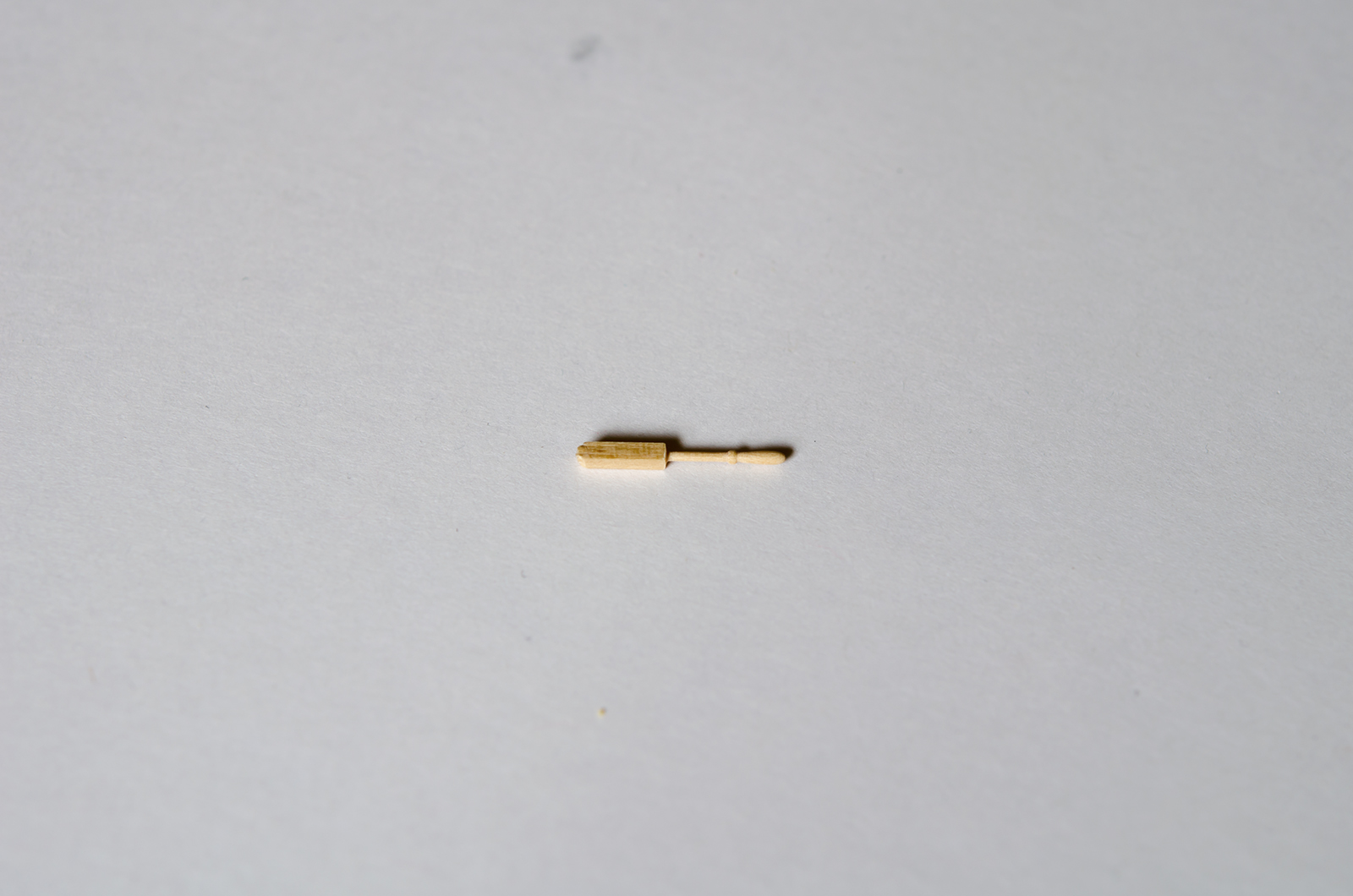
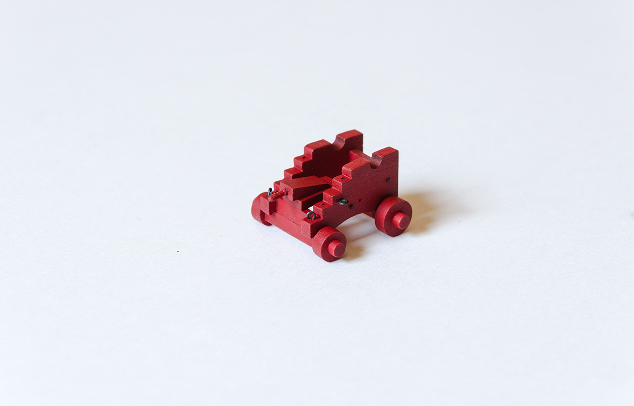
The 12 gun carriages are now assembled and painted. I really enjoyed making them. The breech line ring bolts will be attached later as a completed breech line assembly. Rather than spray painting the carriages, I decided to try brushing them. The goal was to achieve a more natural look. I was quite worried about the paint starting to look blotchy. Using the right brush, thinning the paint and taking your time seems to help the process go smoothly. The Quoin handles were made from 8mm belaying pins purchased from Model Shipways (also sold by Amati) and will be added after the gun tackle is completed. The handle length is only 1/8" and less than 3/64" wide and they could break off easily. I'm quite pleased with the results and will try to brush paint more often in the future.
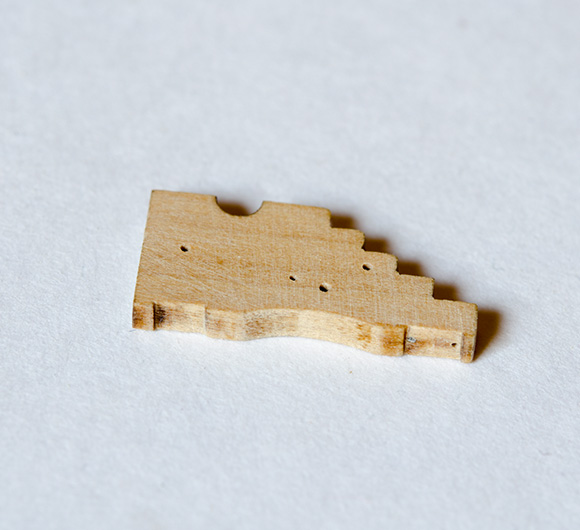
Quoin holding jig for drill press

-
-
-
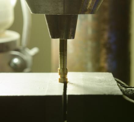
My thoughts in making the gun carriages is to do as much as possible before assembly. I'm using Chuck's laser kit.
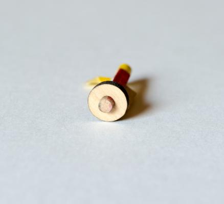
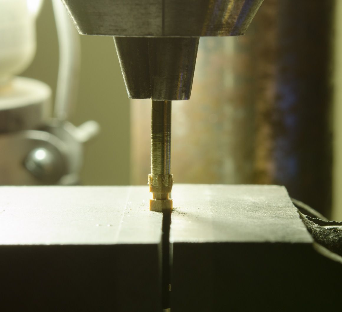
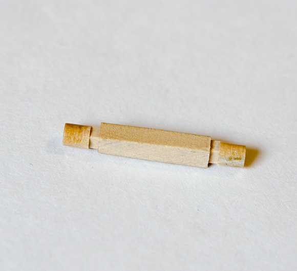
I wanted to come up with a way to make the round axle other than using hand tools. In the photo below, you can see where I slotted the axle to create a 90° shoulder. While in the drill press, 3/32" i.d. brass tubing was filed on the outside to get a sharp edge for cutting. As the brass tubing cuts into the axle the excess wood is parted away. The brass tubing needed a slight sharpening between cuts but the process was very quick.

I used the plan drawing glued to one of the side brackets to mark each hole location for drilling the holes for the eyebolts and pins. At each location a jig was used to hold the brackets in place while drilling. A few pins were installed as well.
I haven't forgotten about the three pin rails or some necessary weathering. I figure that I can work on that if the guns start to get too tedious.
-
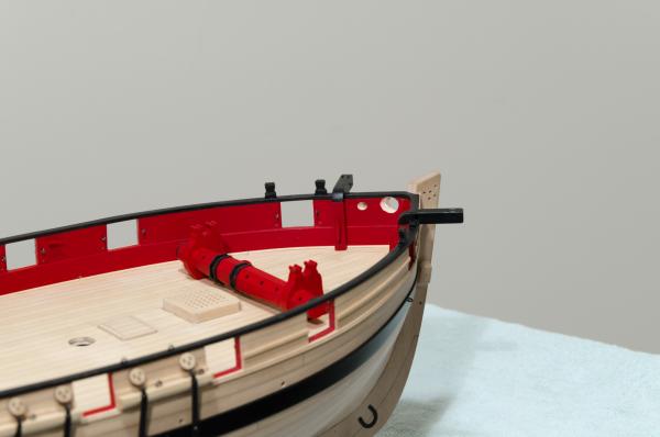
A milestone was reached today along with a a few small updates. . .
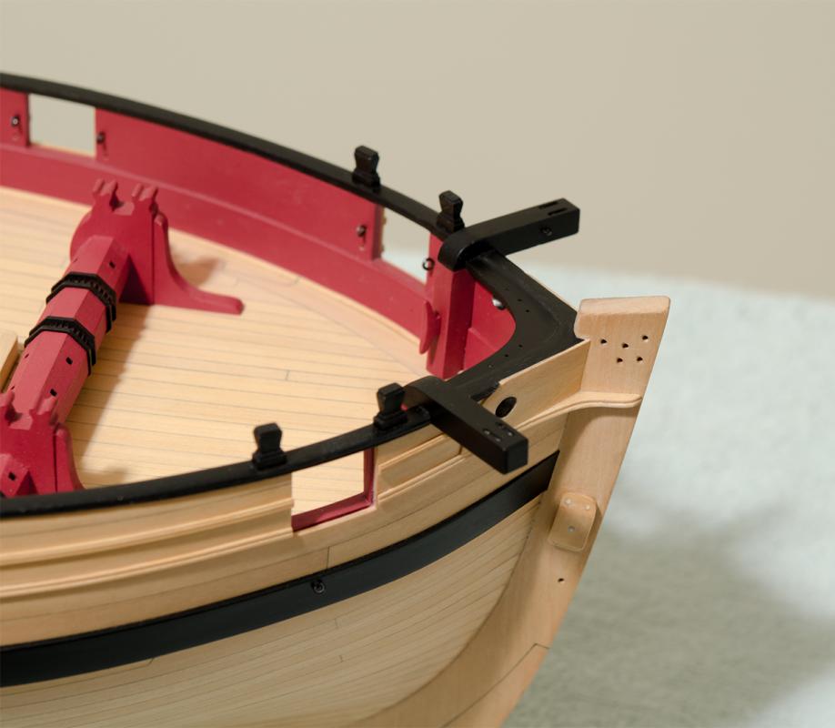
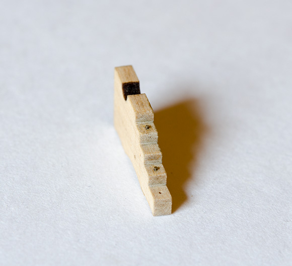
Not surprisingly, it was pointed out at the last club meeting that the starboard side boom crutch was leaning a bit outboard compared to the other one. I was able to correct this after removing it and re-sanding the bottom surface to a slightly different angle. The back of each crutch was also sanded to mimic to the overall curve of the transom. Maybe not perfect, but overall I'm satisfied with the result.
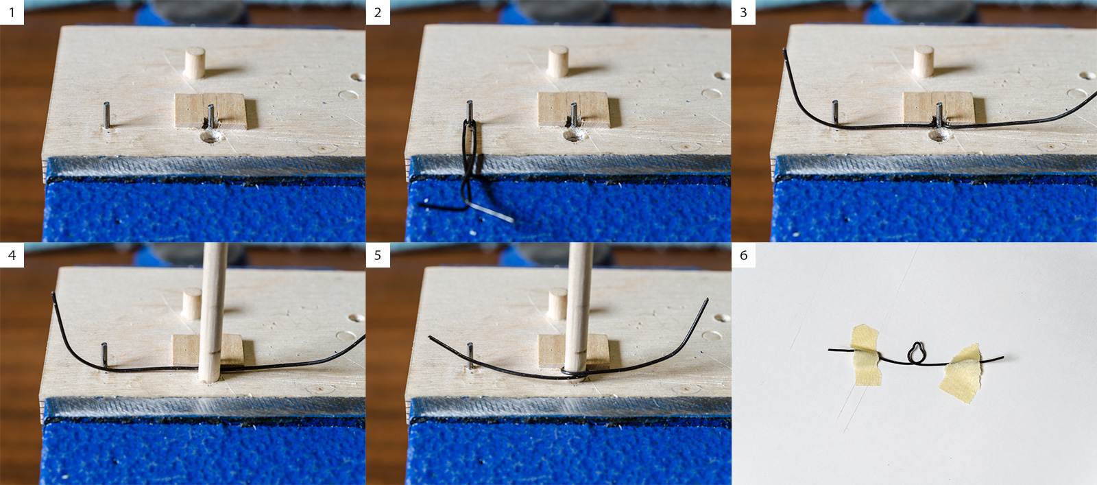
I quickly found that making the strops for the deadeyes (those attached to the chainplates) were going to take some trial and error fitting in order to determine the proper length. A small change and they would rise above or fall too far below the cap rail fancy molding.
With that in mind I made a simple jig to make uniform strops at the proper length. 22 gauge wire was bent around .045 music wire (Photo 2) and formed to the proper length (photo 3). After inserting a 5/32" dowel into the hole (photo 4) the wire is crisscrossed and pulled tight against the dowel (photo 5). The wire was then ready to be cut and wrapped around the deadeye.

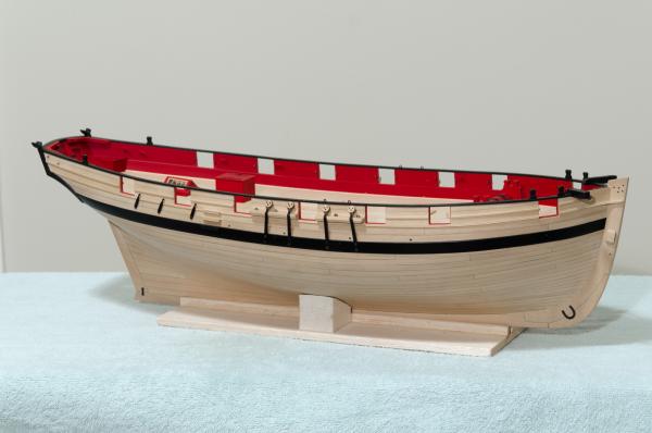
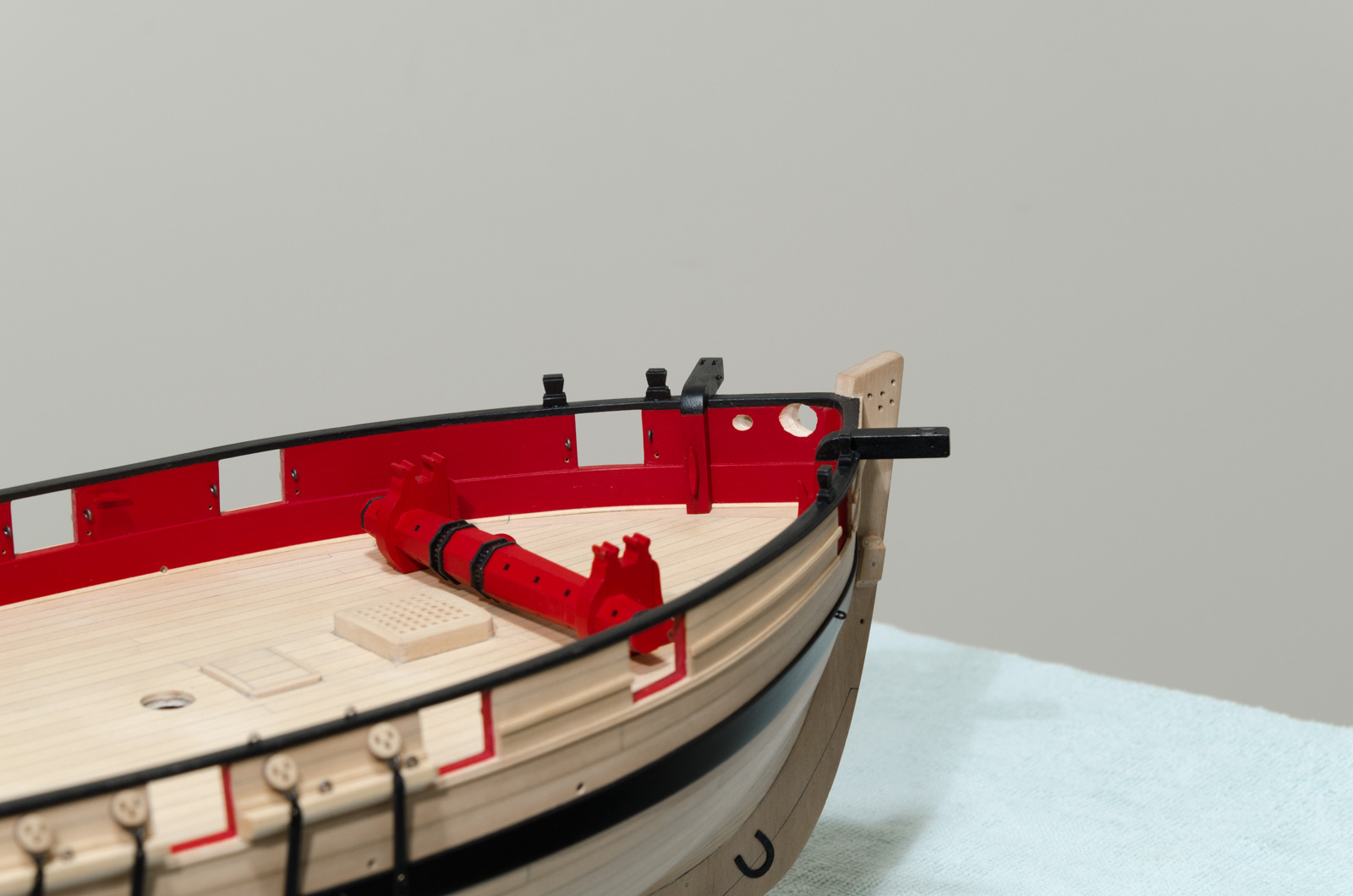
Prior to attaching the chainplates and a number of eyebolts, the wales were lightly sanded, taped off and given final spray coats of Grumbacher "Mars Black" Acrylic paint. I have switched over from the W&N acrylics since having difficulty getting their "Mars Black" acrylic paint to brush on evenly and dry thoroughly. The outer hull details are now completed other than some weathering detail on the plates.
Moving to the inboard details, I drilled out the inboard scuppers and made the catheads.
-
-
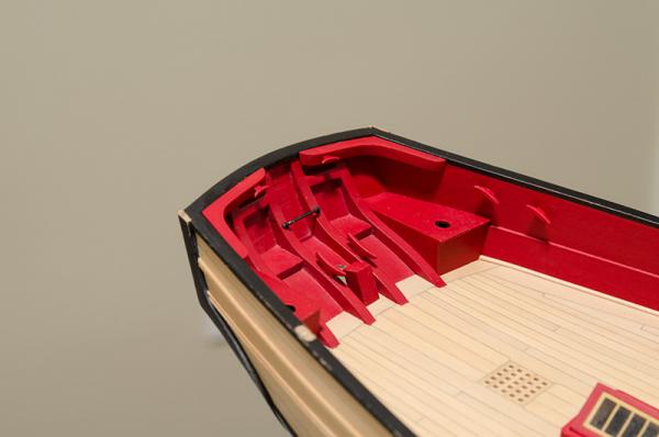
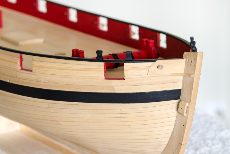
I've been busy over the past few days with the timberheads, those pesky boom crutches and painting. The timberheads proved to be not too difficult as long as I was careful while filing them to shape. The boom crutches proved to be another story as making these put my patience to the test. I only had to make three to get the required two though the process took the better part of a day. I was relieved to get them glued on the boat. The cleanup painting continues. . . .
Viewing the boom crutches from this angle distorts the symmetry of the two pieces but you should be able to get the general idea of how they look.

-
-
-
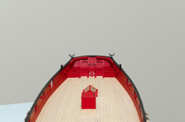
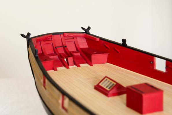
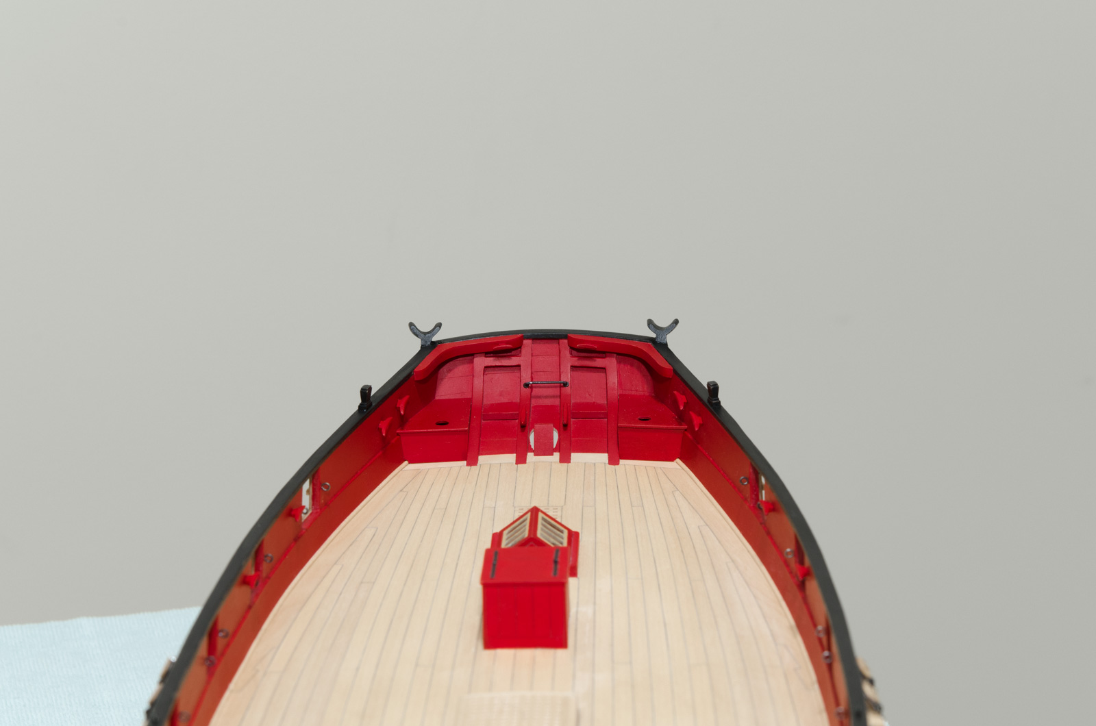
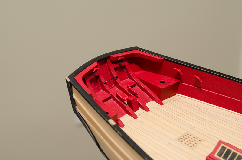
I was able to complete the inboard stern details today. The knees with 5mm cleats, 9mm cleats on the stern frames, 22 gauge wire horse, false stern post and seats were added. There are tiny washers at the base of the horse made from 28 gauge wire. After forming them they were flattened with a plier. The outside diameter is only .065 so they are quite small. Being very hard to handle a few did end up as a permanent fixture in the carpet.


HM Cutter Cheerful 1806 by Stuntflyer (Mike) - FINISHED - 1:48 scale
in - Build logs for subjects built 1801 - 1850
Posted
Thanks Johann,
Your videos are fantastic! Beautiful work indeed.
Mike