HOLIDAY DONATION DRIVE - SUPPORT MSW - DO YOUR PART TO KEEP THIS GREAT FORUM GOING! (Only 20 donations so far - C'mon guys!)
×


Beef Wellington
-
Posts
2,249 -
Joined
-
Last visited
Content Type
Profiles
Forums
Gallery
Events
Everything posted by Beef Wellington
-
 Stergios - don't think you'll encounter any issues installing gratings at this point if you choose to, but doing that later would probably be just fine as well. Its definitely a good idea to do the bowsprit while you still have room, it will also allow you to get the anchor cable installed if you choose to wrap it around the bowsprit bracket/bitts.
- 1,144 replies
-
- 1
-

-
- snake
- caldercraft
- (and 1 more)
-
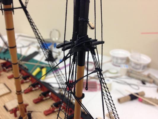
Thanks gents, it was a vain hope to expect for a chorus of voices saying "thats exactly how its supposed to be" Well, 5hrs back, and 3 forward! Luckily the futtock staves came off without any damage, although I was sweating bullets fearing I would cut through a shroud, that would be a lot of rework. Futtock staves re-positioned and topmast shrouds reinstalled (bit of final tie off still to do on port side). Even after moving these there is still not too much of an overhang but it looks a lot better, they really couldn't go any higher. I cheated a little and took the shroud on the inside of the futtock stave rather than the outside as it technically should be because it looked a little better to my eye. The main and fore-topmasts situation will be the same. This may have been a blessing in disguise. The catharpins would have interfered with the driver gaff and associated rigging so I will leave these off following the AOTS Pandora illustration where catharpins are not shown on the mizzen.
- 800 replies
-
- 10
-
-
- snake
- caldercraft
- (and 1 more)
-
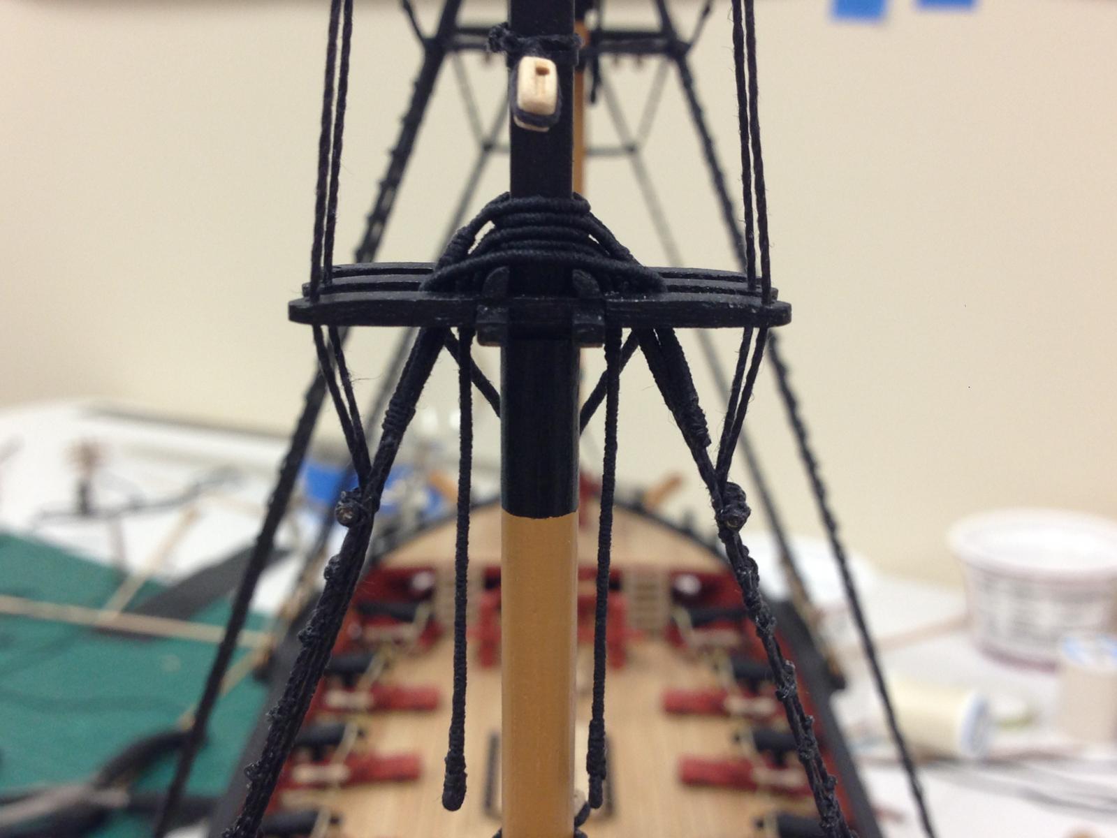
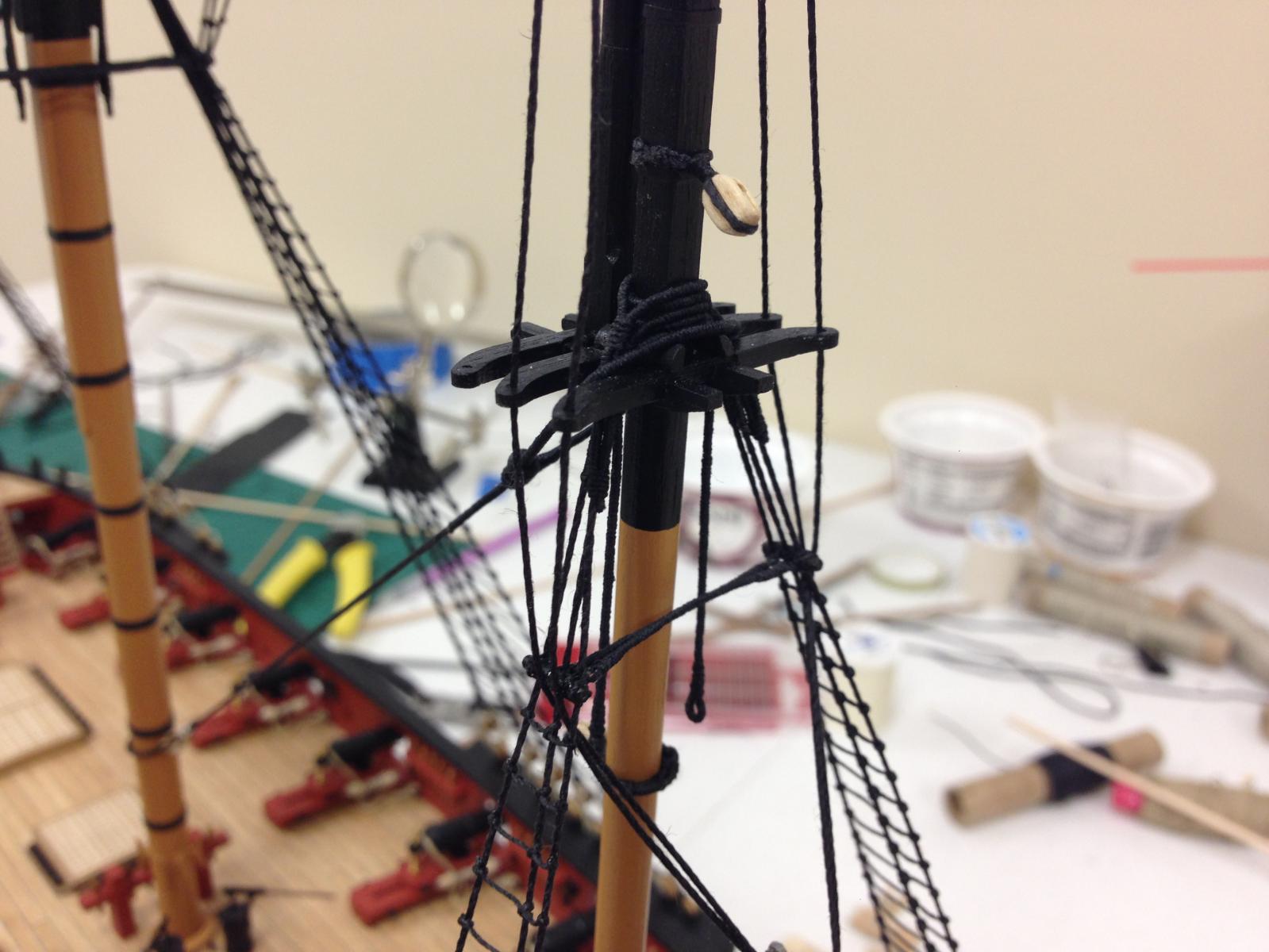
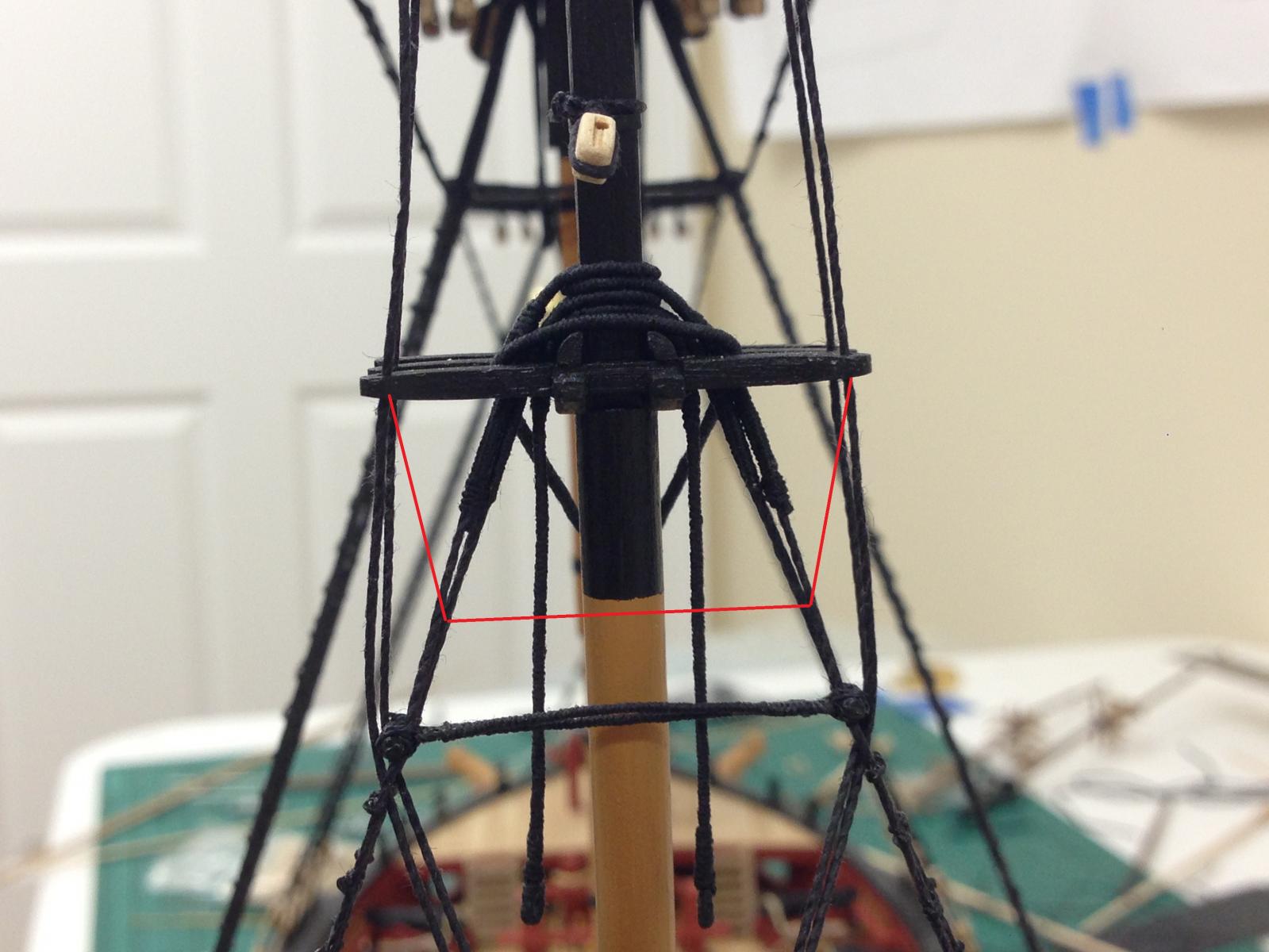
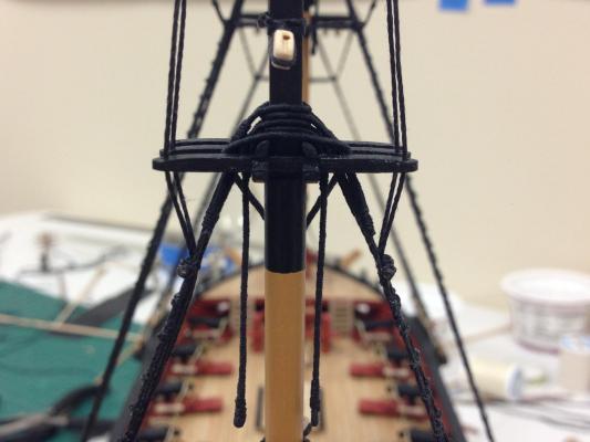
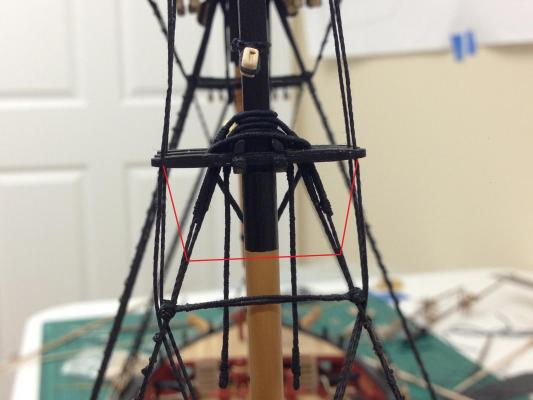
Have been working to get the fine tuning fit and shape of the various masts. Its definitely taking some time to fine tune the fitting of the masts with the various modifications, its amazing how things that seem to be square single result in quite a bit of skew when finally assembled. Picture to close out on the jeers, although I still have the foremast ones to finalise. These seem to be easier to do before the top masts go in. One possible problem that has come to light after getting the mizzen topmast in place. Everything seemed to be looking good until I put the shrouds in place (these go through holes in the cross tree rather than ending in a deadeye). I followed the rigging on plan 3 closely which shows the position of the futtock stave. However, then end result looks very odd, with the shrouds being too vertical below the cross tree. After seeing this I double checked to plan 5 which shows the position of the various spars, and it appears that these are possibly inconsistent. My understanding is that the futtock stave would be placed at the level of the yard so the catharpins can most effectively keep the shrouds from interfering with the yard operation. Taking all that into account, I think what I need to do is relocate the futtock stave higher to be level with the placement of the cross jack yard. This would then give the futtock shrouds a better lie (see added red lines below). Before I commit to this (it probably involves some risk as well) I did want to see if I'm misunderstanding this or looking at it the wrong way, or just others thoughts/opinions. As always, comments are most welcome. Futtock shrouds look very odd with currently positioned staves, proposed relocation in red...
- 800 replies
-
- 7
-
-
- snake
- caldercraft
- (and 1 more)
-
Jim - I'm struggling a little bit with this as well, obviously boils down to individual preference, but the methodology link you have looks a great way to go. There seem to be pros and cons to either way of approaching them. For the smaller blocks and line, I don't see too much of a problem with knots as they can be quite subtle - I've found it more of a problem on the larger blocks using the larger line when the knots become unacceptable. I know I'm not helping.. One possible additional option would be to rig the blocks to the rear eyebolt instead of the sliding bed, as this is how a number of ships have them rigged - doesn't seem funtional to me, but its a balance with aesthetics. I've seen a number of modelers also rig training tackles but I've read (somewhere) that these weren't really used in practice, but it can make a strong visual impression.
-
Thanks Colin. Yes, the blocks on the cap are attached to eyebolts...must have been a little sleepy when I wrote deadeye! I'll see what I can do with the taper, I definitely get where you're coming from. As for the stays, I think I'm going to go with the thimble approach which is also shown in Peterson, there is no mention of a thimble in the CC plans/instructions. Thanks for the pointers, much appreciated!
-
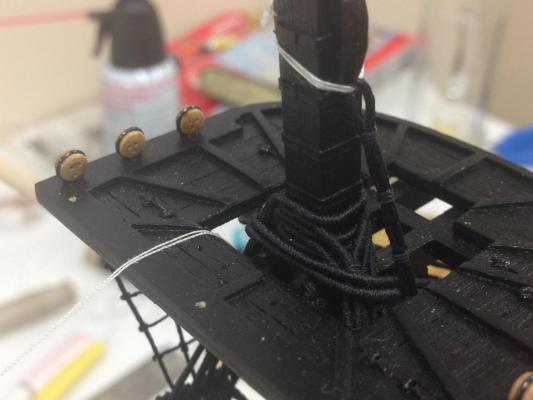
Nothing complicated. The small holes (green arrow) were done when I was considering pinning the gratings to the deck, these were covered up when grating glued in place. The larger holes (red arrow) are for the anchor ropes, the reason they are so ugly is because I found out that a bulkhead sat right below where I wanted these so it took a bit of effort to remove enough material so I could get the ropes to feed in correctly.
-
I see there is a separate discussion on this. I can't help feeling that this probably wouldn't have been a very effective method for providing drinking water considering the necessary large fuel supply needed to generate the volume of water needed for a crew. Conjecture on my part was that this was used for limited 'specialized purpose's (captain/officers food delicacies, sickbay needs etc) rather than a source for crew as a whole. I'm sure others could comment more authoritatively.
-
Thanks Ray for sharing, very nice progress pics, shes really coming together. Love deck shots. On the barricade, I have seen a few admiralty models with these painted/stained black and thats probably the route I would choose knowing the wood would probably not look the best left natural with what I'm assuming is ply.
- 536 replies
-
- 1
-
-
- diana
- caldercraft
- (and 1 more)
-
Thanks Colin - my comments: Duh, should have though of that, I'll give it a go tonight and see how I get on. I can't find much guidance on this but looking at picture it seems like the line used to strop blocks needs to be somewhat proportionate to the size of the block otherwise it just just doesn't look right. The block in question here is an 8mm violin/sister block for the lifts. Anything smaller than the CC 0.75mm line looks too small to my eye (The CC line sizes seem to be err on the large side, the 0.75mm seems closer to 0.5mm, and so on...) You are so right - but I'm going to need to leave turning my own spars for 'next time'. For the main yard, the central section is 6mm and tapers to 3mm (per plans), haven't got as far as painting these yet so will wait to see how they appear A specific example (though there are more) is for the mizzen topmast stay (there is no topgallant on Snake) and it shows the stay seized around the top mast ans then seized to a ringbolt on the the main top. (On the plan, its really just a line, I'm inferring it should be seized). Thanks for the thoughts!
-
I'm making some very broad statements here, hopefully on point. Ship designs were probably more heavily influenced by naval startegy and national policy as much as anything. French ships were typically lighter built, because this made them fast which was needed to support their doctrine of ships putting to see for a specific purpose and otherwise moored in harbour. The downside was that they were not built for endurance. The opposite was the evolved British strategy of having ships continually at sea supporting the strategy of blockade or on distant station, which required stronger ships built for endurance. For both these countries this had to fit within an extended window of hostilities. In that context, the war of 1812 was pretty condensed with Americans essentially following a localized commerce raiding strategy and building highly effective ships for that strategic purpose. Britain responded by building similar sized ships on a limited basis to counter that specific threat, but maintained its underlying commitment to it long standing approach to ship design which worked well both before and after . Bottom line, every ship is a compromize of cost (building and operating), firepower, sailing quality, speed and endurance amongst others. Ships were probably much less influenced by the skills or training of the individual shipwrights than by the direction of the individual Admiralties in support of military strategy and national policy.
-
I didn't pin the gratings, just glued to the deck. All the other fittings (especially the pin rails) were pinned as these need to take some strain from the rigging. Matt (uncoloured) varnish was used on everything.
-
Michael, JesseLee, Jim, Sjors, Timmo, Dimitris, Tim - thanks for stopping by and the kind words Tom - great to meet you as well, the pleasure was all mine No photos I'm afraid, but couple of things in process. Seem to have spent far too much time pondering and not enough doing. Trying to find a tidy way to attach a block to a deadeye using .75mm line and am struggling a little. Its a bit thick for using a simple knot, and seizing works but am not sure how strong it would be. Using thinner line looks underscale to me looking at contemporary drawing. Any advice welcome. Working on final shaping of the top-gallant masts. These are proving to be a challenge as it seems that every single piece of dowel is slightly bent. Even after selecting the straightest pieces its proving a little challenging. Thinking ahead to the rigging of the remaining stays, there are a couple of areas that I think I want do differently to the plans. These indicate a couple of the stays that are simply seized at both ends. I would have thought that every piece of standing rigging would be adjustable in some way to allow changes to be made in tension so may follow some of the diagrams in Peterson which seem to support that.
-
Nils, hope this helps. The anchor rope would be secured around the riding bitts as in picture below (just behind the forward platform, although they are not technically riding bitts on the Snake the principle is the same). The cable then passes through soem holes in one the grating over one of the hatches. The rope would then feed down onto a lower deck called the 'cable tier' where the rope would have been coiled. It was probably a very smelly place given the wet mud that would be covering the rope.
-
Nice upgrades there Jim, big improvement and nice with only 4 to do . Did you also drill out the barrel? I think Pete did that on his Snake to pretty good effect, but then I saw that on Ray's Diana he just painted the ends red to simulate tompions and that seemed to look pretty good too. Would be nice to see a photo of one next to a 32lb'er on your Snake!
- 226 replies
-
- 1
-
-
- ballahoo
- caldercraft
- (and 1 more)
-
Looks great Nigel - the first photo really shows the lines, much more interesting (and I'm assuming challenging) than the later ships. Intrigued to see how the stern comes together.
-
Very nice work there Timmo, those are very interesting deadeye strops, never seen them like that before. I experience exactly the same issue on Snake, its like playing russion roulette, no matter how much you try to get it correct, there seems to be one that doesn't work. I decided not to try any drastic fix simply because the angle of the chains and the different viewing angles mean that it doesn' really jump out at you (and no-one else will notice). In my opinion, its viusually more important to have the chains looking consistent and angled correctly than adjusting them to allow the sweep port to theoretically function. My opinion only.
- 366 replies
-
- 1
-
-
- granado
- caldercraft
- (and 1 more)
-
I would think that that would be the trick, but I could see this being a slow process! I'm guessing the template is OK to find the horizontal position, but can only really be used to approximate the vertical position, the interior deck height must be measured to get that right. It also seems that that would be important to get the wale alignment correct, so getting the interior deck in correctly seems critical to later stages. I'm impressed and a little daunted if I follow in your footsteps!
-
Looks great Sjors, I don't remember seeing any pics of how you did the gun port lining (?), they look great. Any insights (photos!) into your basic techniques would be greatly appreciated!
-
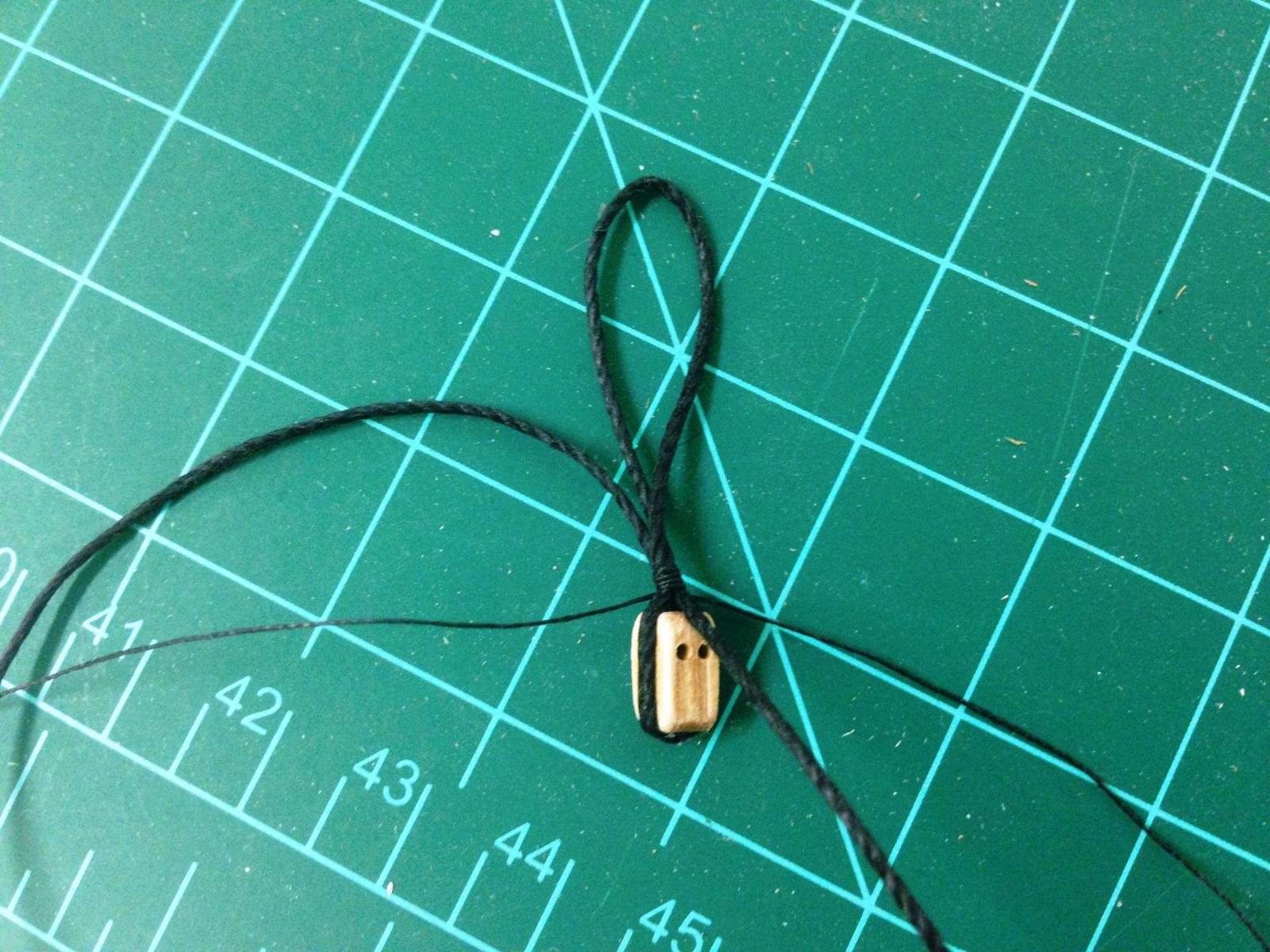
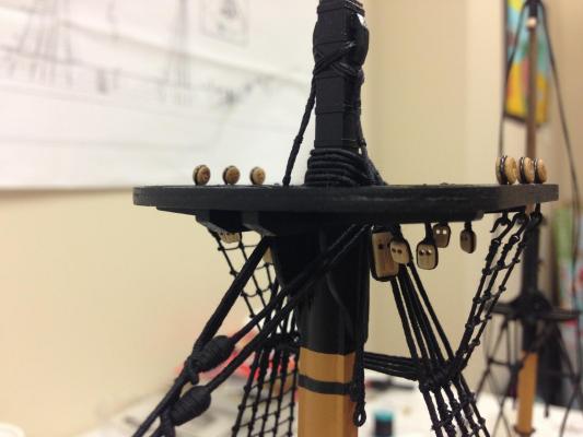
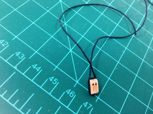
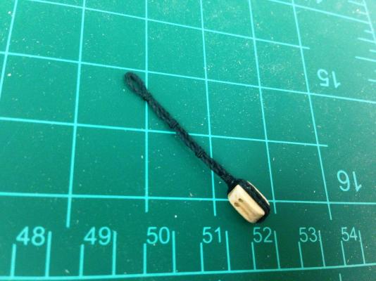
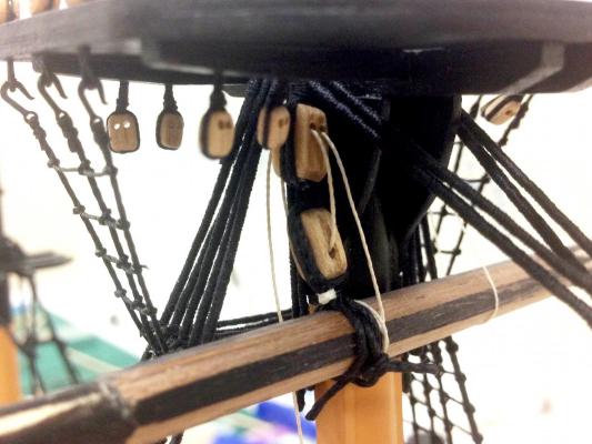
Jeers: Although topmasts are pretty much ready to go on, the jeers have been nagging at me. These seem to be pretty awkward to get in, especially once the topmast shrouds are in place so I've decided to install these before the proceeding further. Getting the right length required quite bit of trial and error. As always, suggestions welcome. For some reason photos came out particularly badly tonight, so apologies in advance. Block double stopped and kept in place with few drops of GS-Hypo. Loop added to provide correct 'length', the three stands then seized near the top of the block. Loose ends trimmed, and additional seizing put on. I did this in accordance with the Grenado AOTS diagram (i.e. unserved), although it seems that these were also commonly served. Frankly I didn't have the patience to attempt that...but suspect that the method could work just the same. Mocked up the installation to check again length is appropriate. There is not much room for error here, and it took multiple attempts to get length correct. Looks OK to me. Jeers will be lashed to the mast cleat on opposite side, this again is just a temporary mock up to prove it works.

- 800 replies
-
- 19
-
-
- snake
- caldercraft
- (and 1 more)
-
Simply unbelievable, inspirational work Danny in all respects, have followed from the start and will be here until the end.....<...speechless....>
-
Carronades look great Stergios, very neat indeed. as far as the ends go, in pictures I've seen they just hang loose for a below any frapping but well clear of the deck. Each one seemed to have a mind of its own but cam off OK. I think with your professional skills you'll be setting the standard here
-
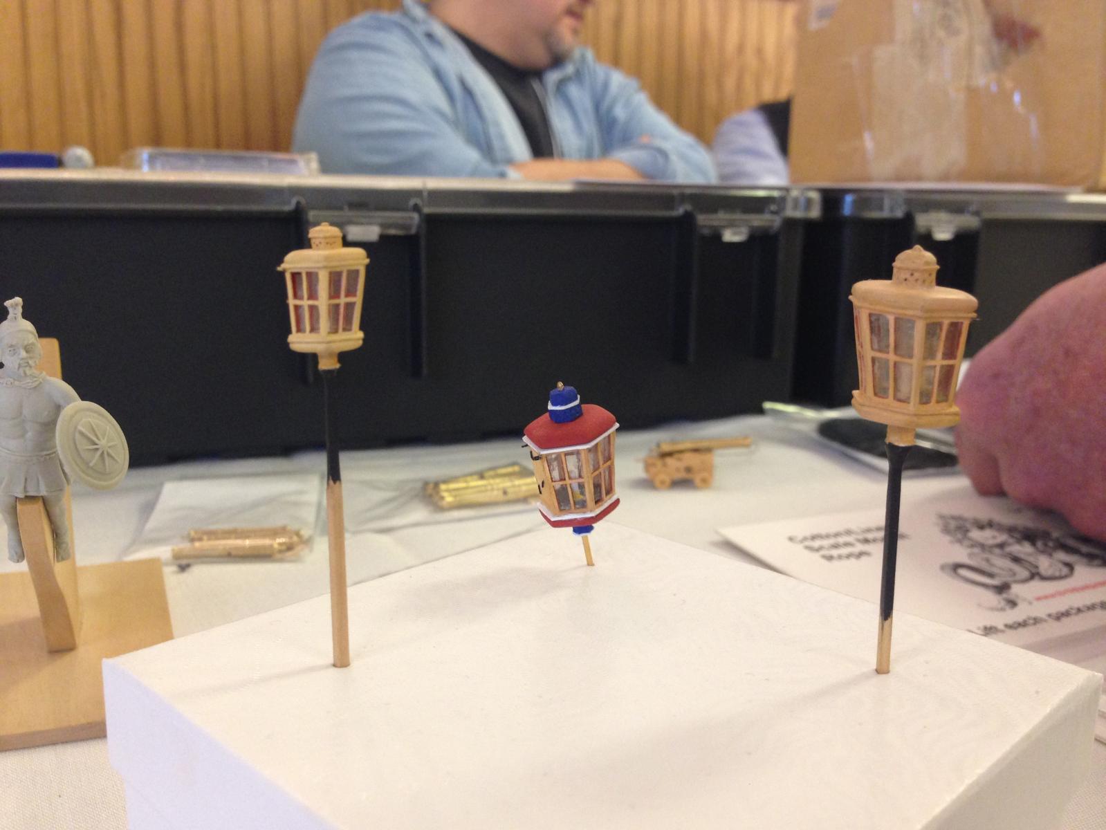
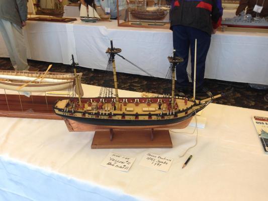
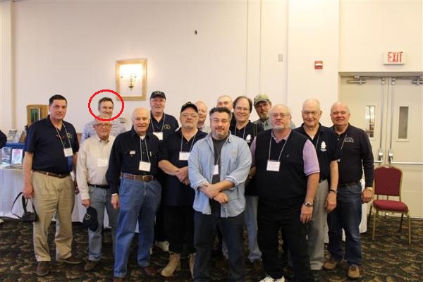
Cheers Mike, sorry I missed your kind comment - thanks mate! No real progress of sorts, but a few pics of the Snake's first voyage to the NE Join Clubs Ship Model Show (There are some great pics at the following link). It was great to meet some folks face to face and see some really nice models and some in person from logs right here on MSW. http://modelshipworld.com/index.php?/topic/4939-northeast-joint-clubs-ship-model-show-conference/page-2#entry191448 Sjors/Mobbsie/Pierre/Klaas - You should check out the pics of HMS Ardent, I think it was bashed from the Agamemnon kit but was heavily modified - it won best in show and was pretty impressive! Hopefully with a bit of work in the garden done I can get back to a bit of modelling in near future. MSW group photo, Chuck in front and me lurking in the back Snake (very humbly) on display - the big boys are in the background Chuck's stall, fantastic stuff that I will no doubt be using in the future, had to share a picture of his lamp kits

- 800 replies
-
- 9
-
-
- snake
- caldercraft
- (and 1 more)
-
Fantastic Jim, you have set a very high standard. One possible suggestion if the planks aren't glued - I believe that there would not have been any butt joints between the hatch/companionways where a regular plank length would have been sufficient to cover distance between them. I found that out after I had done mine on Snake but luckily I was able to hide the main offender with a slightly re-positioned companionway coaming.
-
Very nice Jim, definitely want to try this next time - clarifying question, are you glueing the deck planks as you go to help keep the margin planks in the same place?
-
What a wonderful build you have going on here Mark, really outstanding. Will definitely be following from here on.