

Moonbug
-
Posts
948 -
Joined
-
Last visited
Content Type
Profiles
Forums
Gallery
Events
Posts posted by Moonbug
-
-
Very much enjoying your build Masa - the illustrations and commentary are all quite fun! Not to mention the wonderful job on the build itself.
- Dave_E, modeller_masa and Louie da fly
-
 3
3
-
Good morning JayBee and welcome the forum. As you might expect, your question is near the top of the list for new members. To that end, there is a discussion about kits and manufacturers here:
https://modelshipworld.com/forum/24-wood-ship-model-kits/
Lots of good information, including some first-build options.
- JayBee750, Keith Black, mtaylor and 1 other
-
4
-
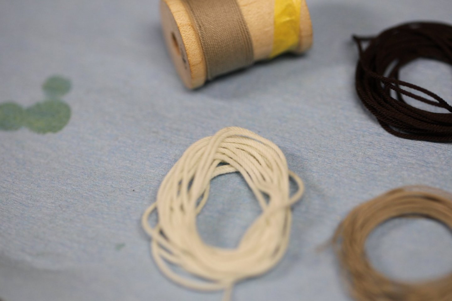
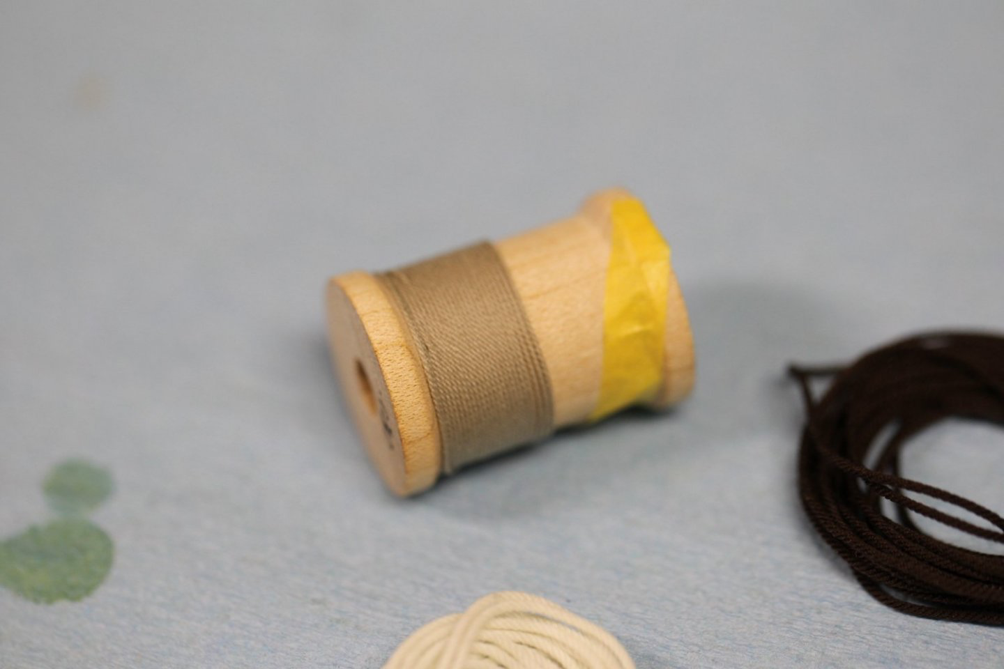
Good morning,
I first posted this in the rope making club(?) and didn't get any responses, so I thought I'd try here instead. I'll delete my other post so it's not doubled up on the site.
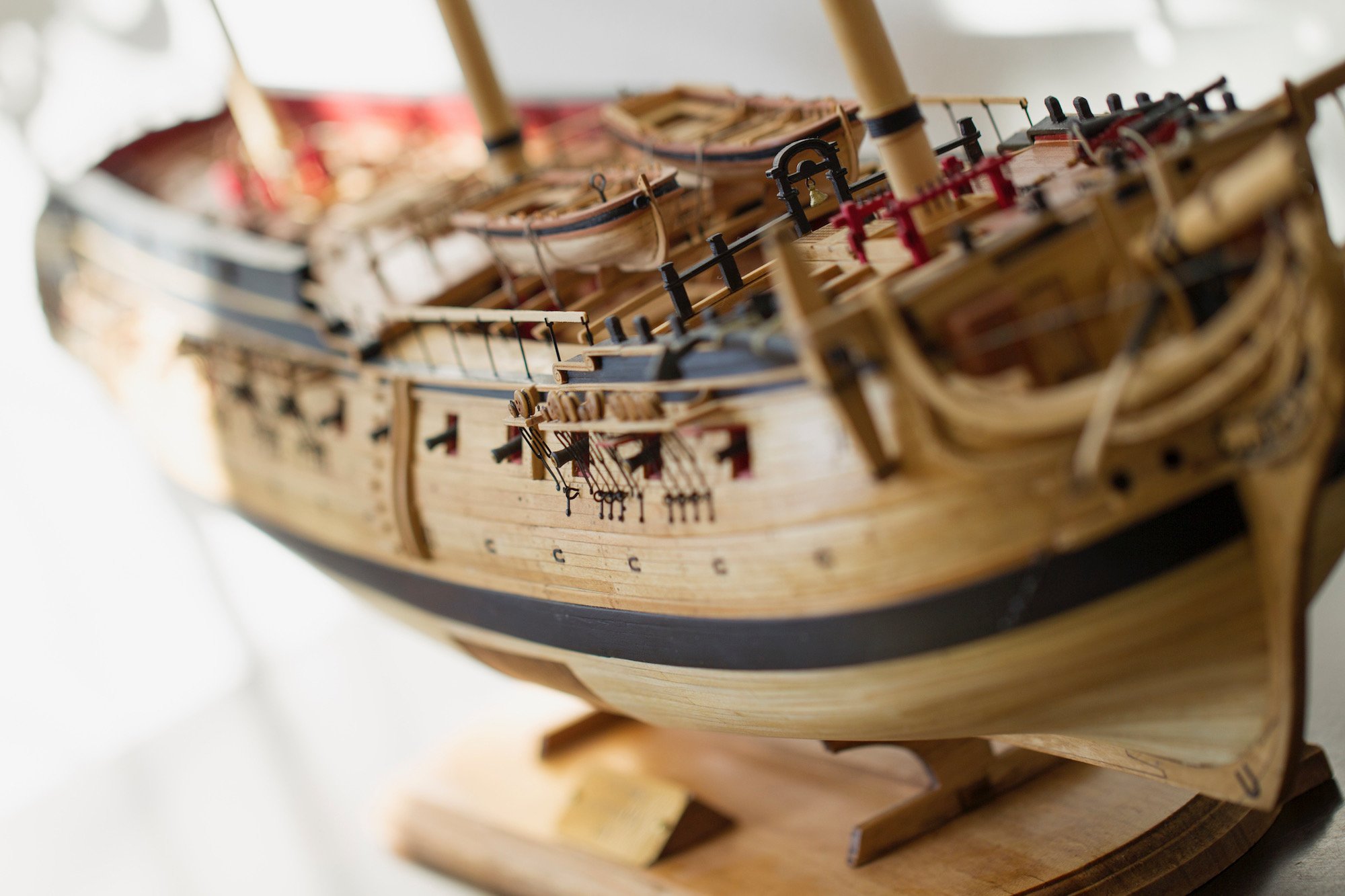
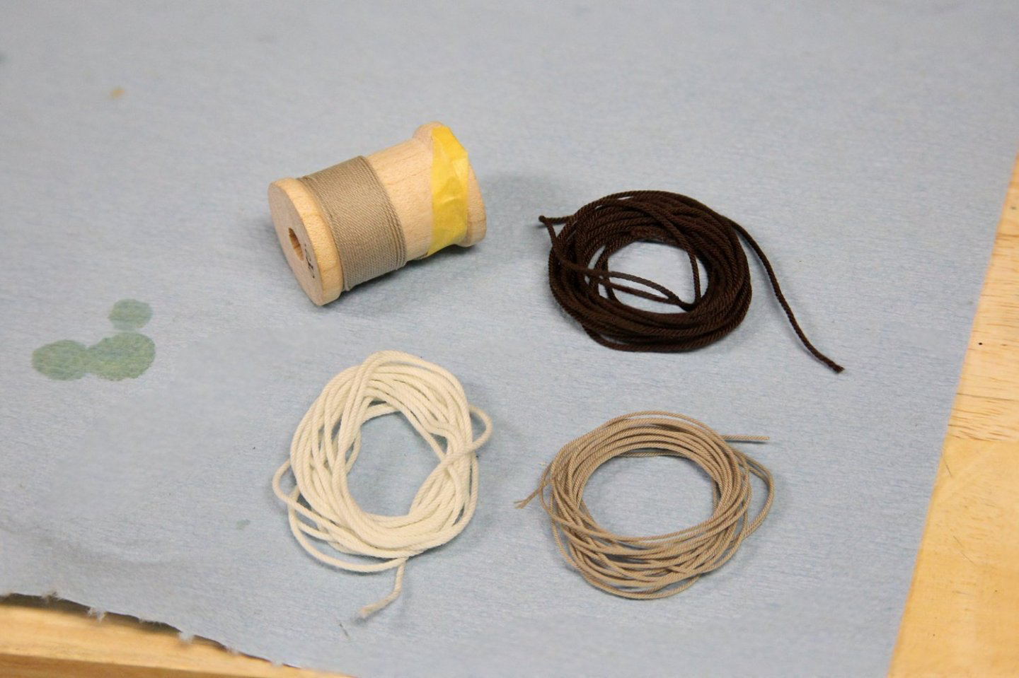
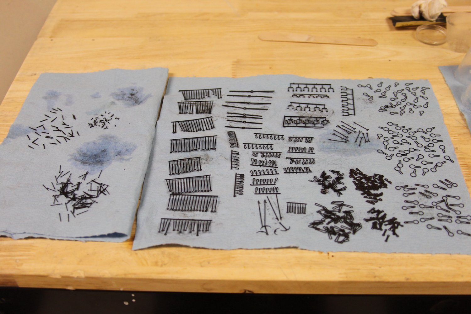
I just received and put together @Chuck's Rope rocket and I'm pretty pleased with it of course. Like others I'll just add again: be sure to watch the videos. Aside from the basics, there are lots of tid-bits that really help out.
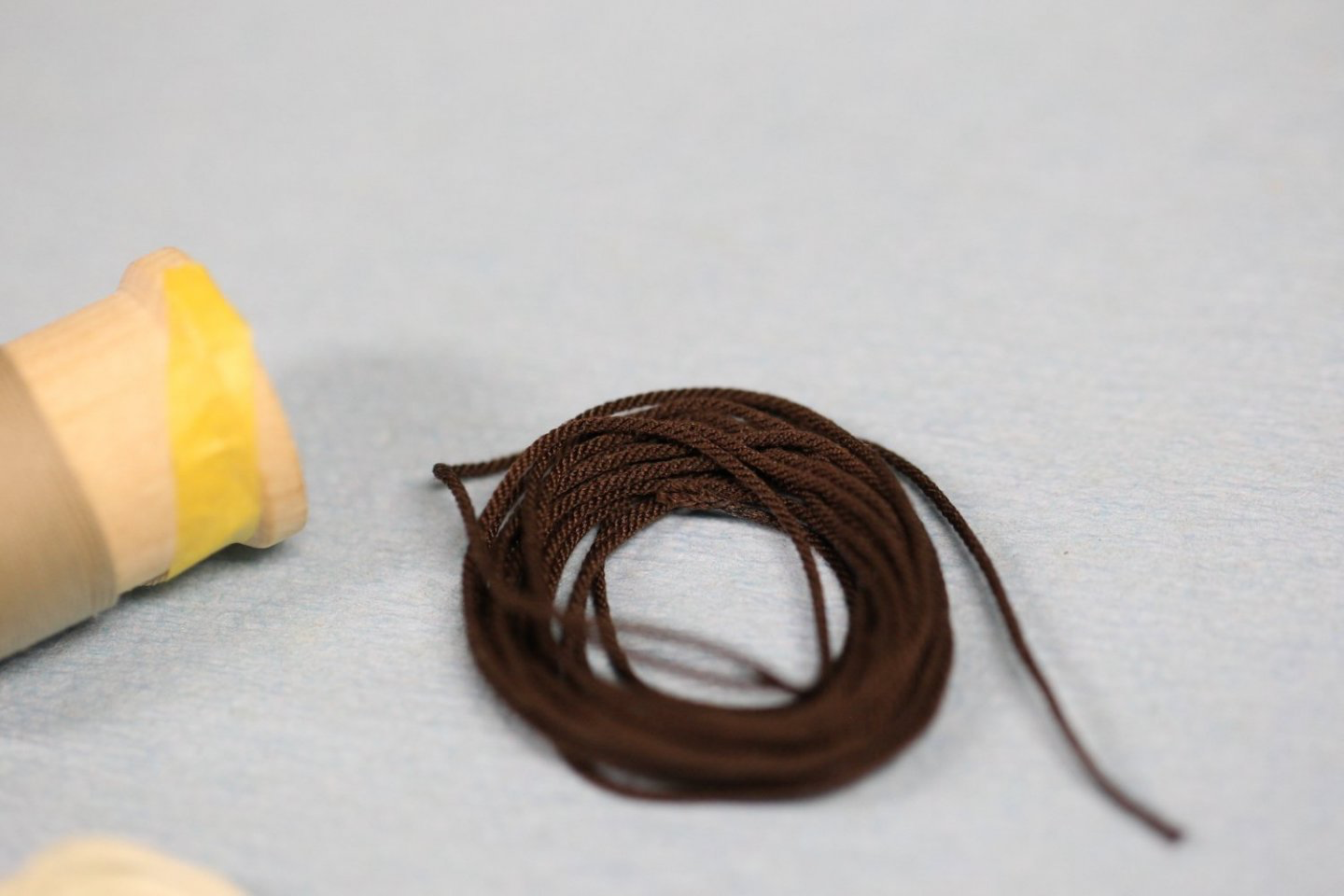
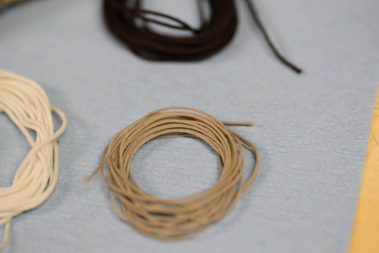
That said - I'd like some feedback on my first few attempts with different colors and sizes. I'm using the Mara 30/70/120 sizes and tried both 3 and 4 strand rope. I'm not sure however if I'm tightening the rope TOO much - and I'm also not really sure how to tell if I am. Doing my best to feel the tension, but still unsure.
I'd like to try to solidify my technique and sizes before I get to rigging the Pegasus.
Any feedback is greatly appreciated.
- mtaylor, The Gimps Chimp, wefalck and 3 others
-
6
-
Thanks B.E., appreciate it. They're definitely a lot small than one realizes.
43 minutes ago, Blue Ensign said:My Capt. Grim looks like an extra from 'Fear the Walking Dead'
Ha! Too funny. Than again, Capt. Grim has been around a long time - I'm sure we can forgive if he perhaps has not aged gracefully...
")
-
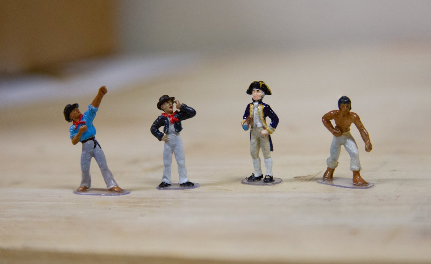
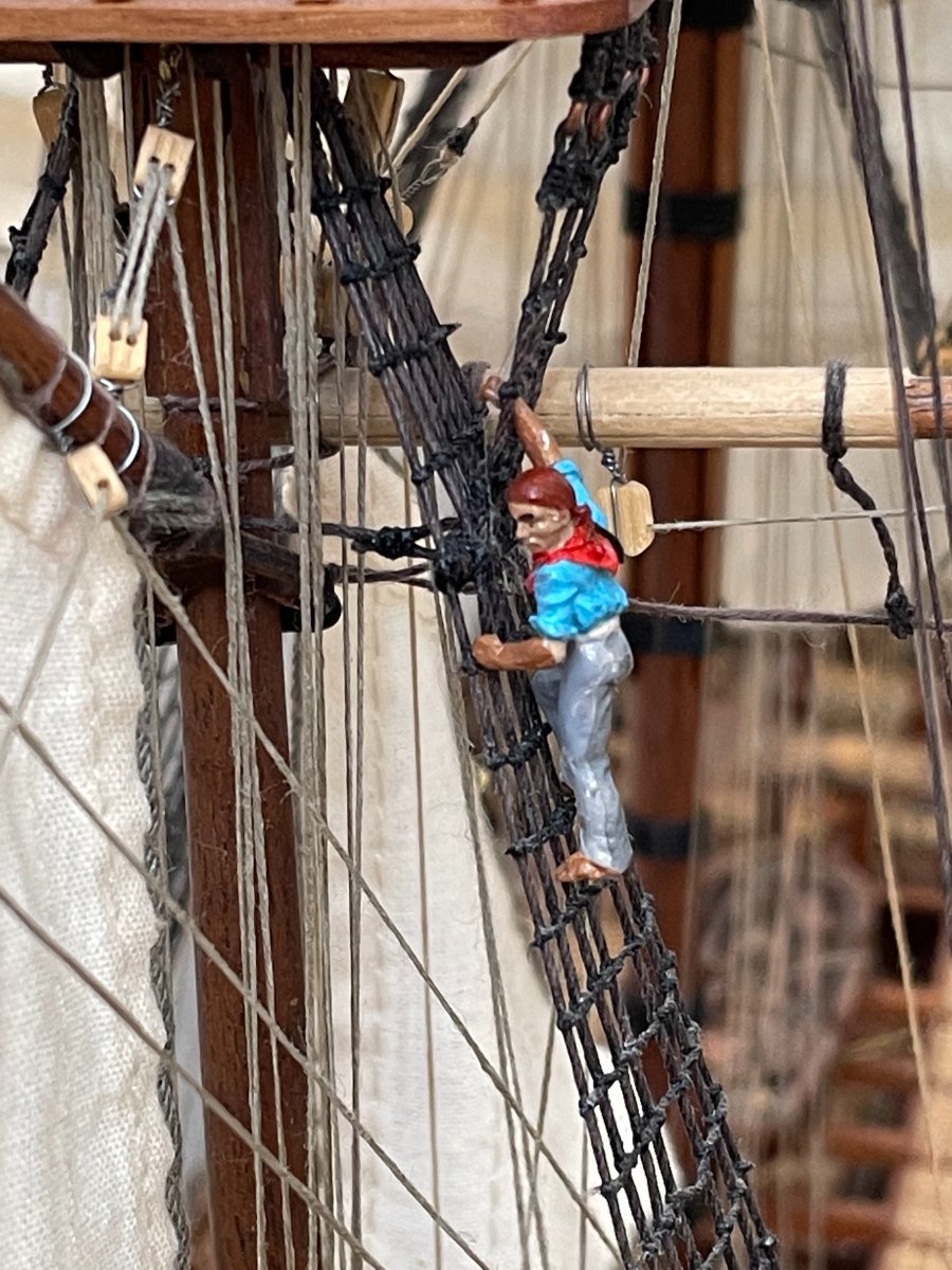
Hello everyone. I did not fall off the face of the earth - only to Mexico for holiday with the admiral. One day she got fed up with her work (we both work from home at the moment (Covid rules apply) as well as the cold Colorado winter and rather spontaneously booked a trip to a resort in Yucatan. Who was I to argue? I'm an anthropologist so I was happy to finally see one of the "new" seven wonders of the world - Chichen Itza, and I'm also a golfer so I got to play a round at the Riviera Maya PGA course.
Meanwhile, while we were away - the ubiquitous and certainly infamous Amati Crew arrived, so I painted those fellas up and mounted them on small bases made from a leftover hard plastic container. Except for climber-guy of course. I've never considered myself very adept at painting by hand (which is why I airbrush so many things), but I like the way these guys turned out. Just for fun I tried to give them a little extra realism by adjusting their skin tone depending on their job and exposure to the sun - ranging from the pasty white Cap'n to the super tan fellas.

-
-
Thanks for the likes, etc - and the comments Grant and Bob!
2 hours ago, BobG said:I need to learn to silver soldering
Thanks Bob - Basically just trial and error playing around with which solder paste works best with which type of metal - then practicing when to let off the flame.
-
-
That looks great Popeye!
- mtaylor, Egilman, popeye the sailor and 6 others
-
9
-
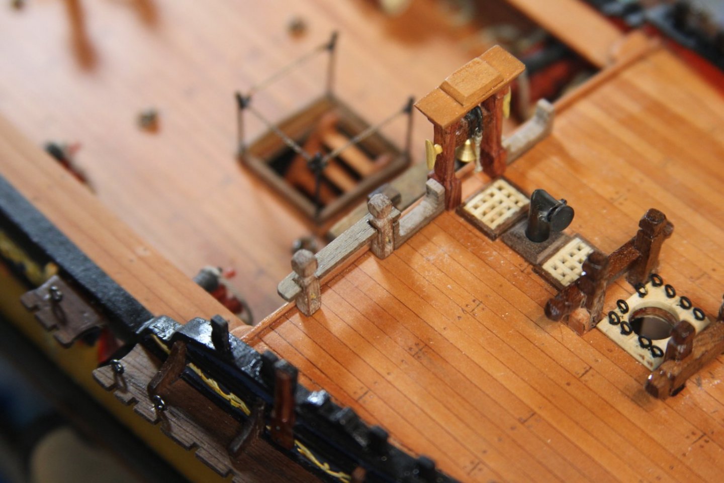
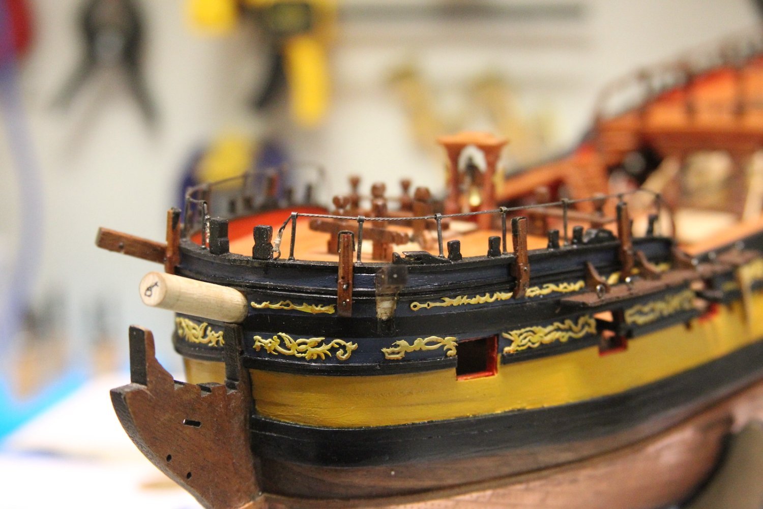
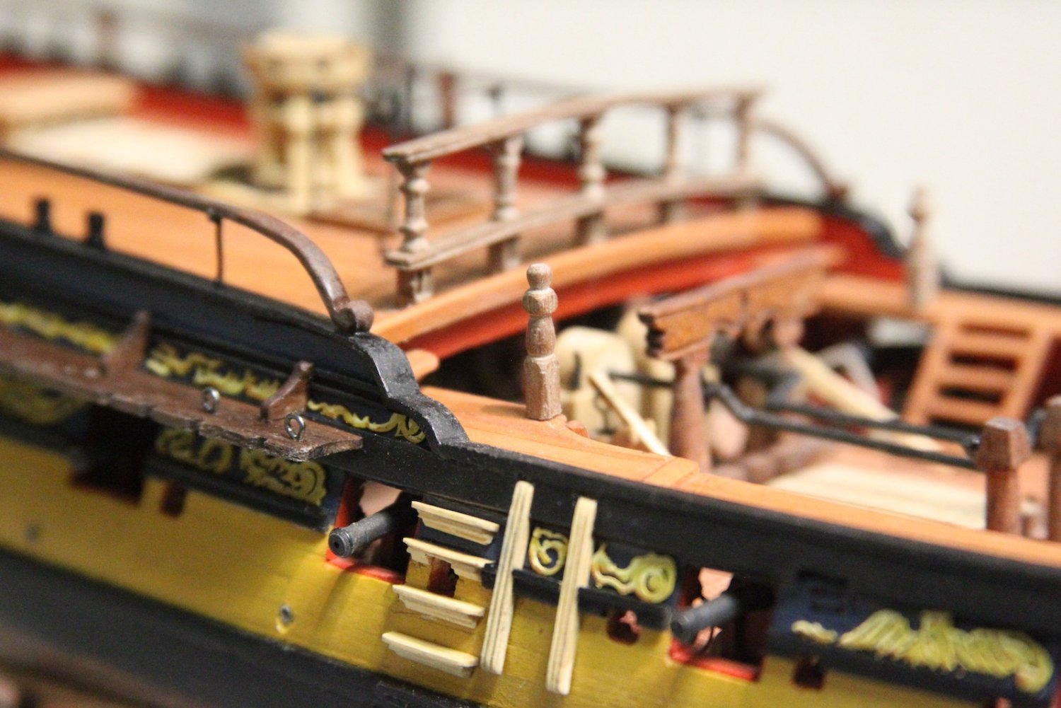
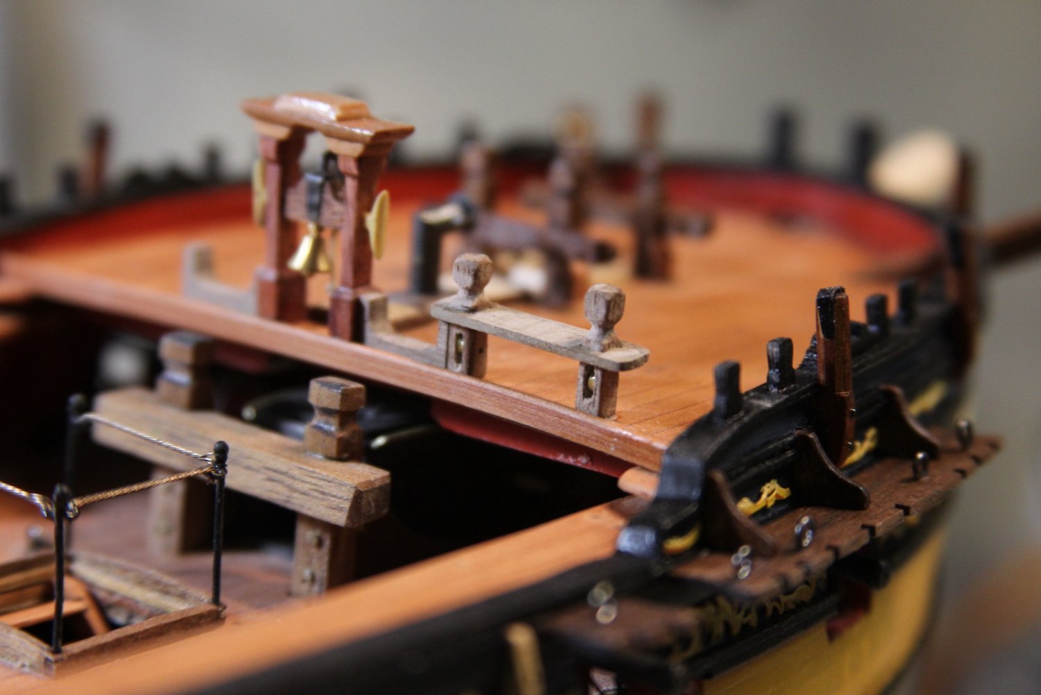
There aren't a lot of pictures of the making of the forecastle railings - which belies just how difficult and fiddly these little buggers were. I had some really specific in mind for these ever since I saw Dan's version from the FFM. I wanted the same stanchions, but once again I really dig the little bit of coiled wire that I have and used for the hatch railings. Now as far as accuracy is concerned; it definitely falls into Category #2 under my previously explained decision tree: "Not 100% accurate, but looks cool."
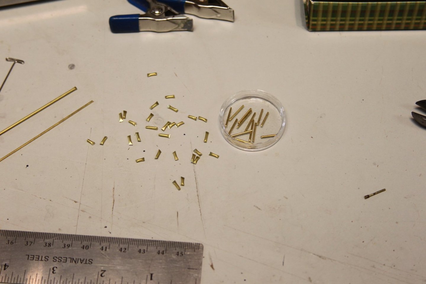
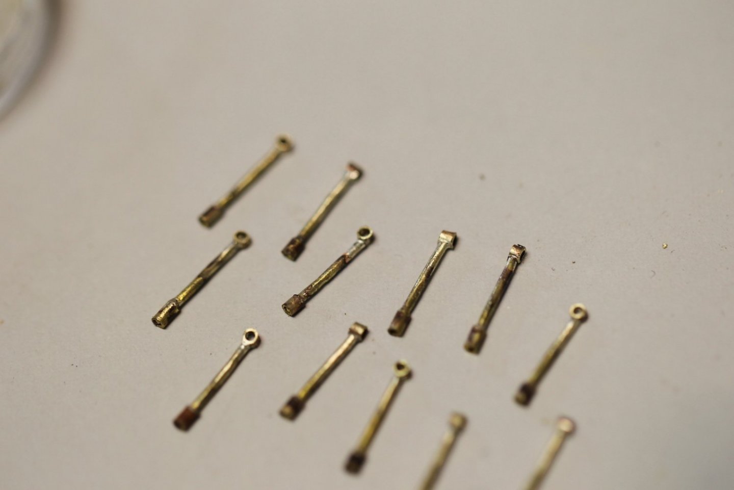
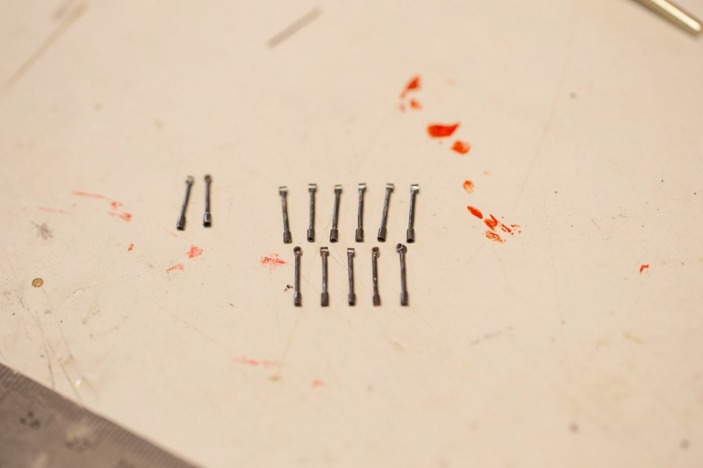
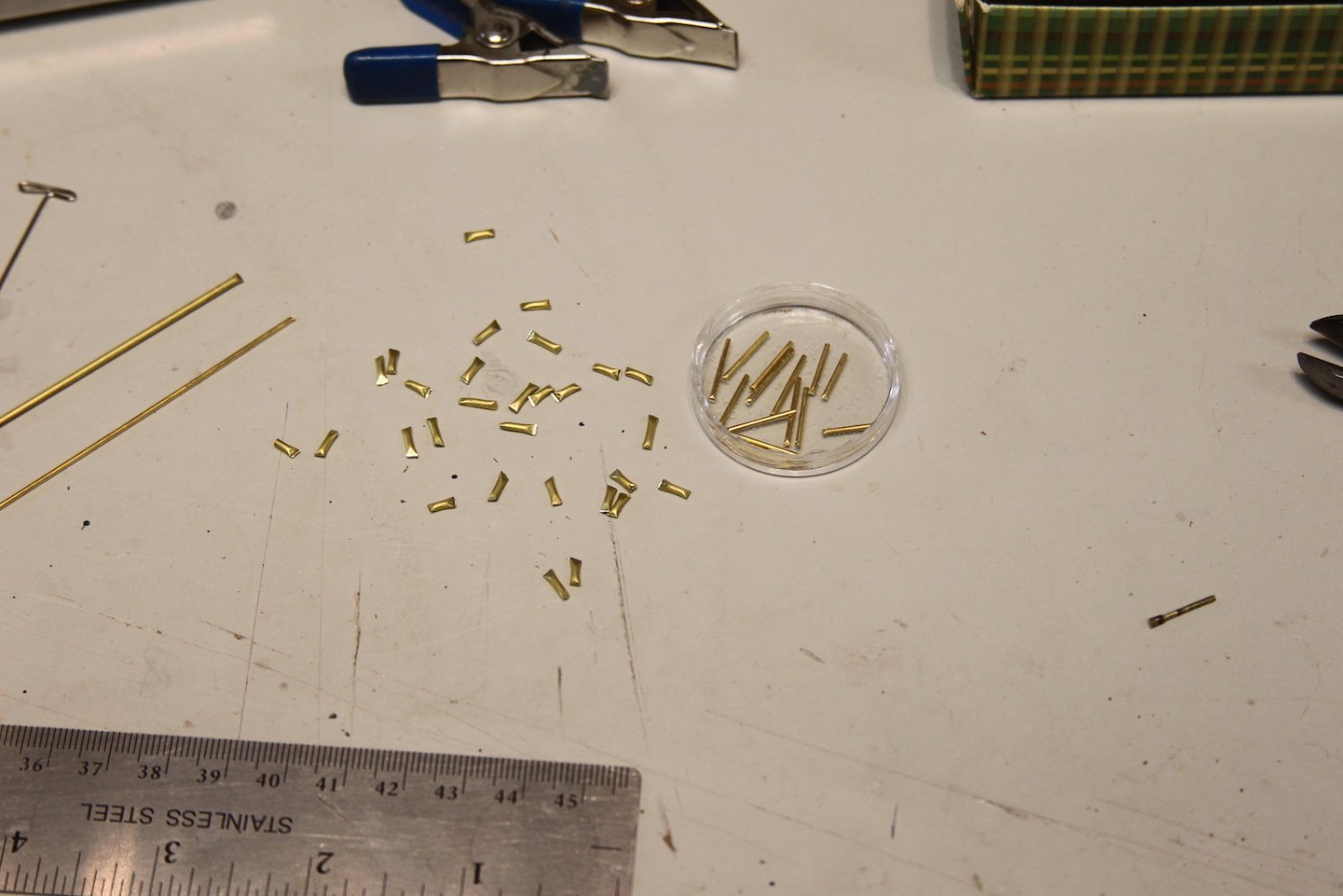
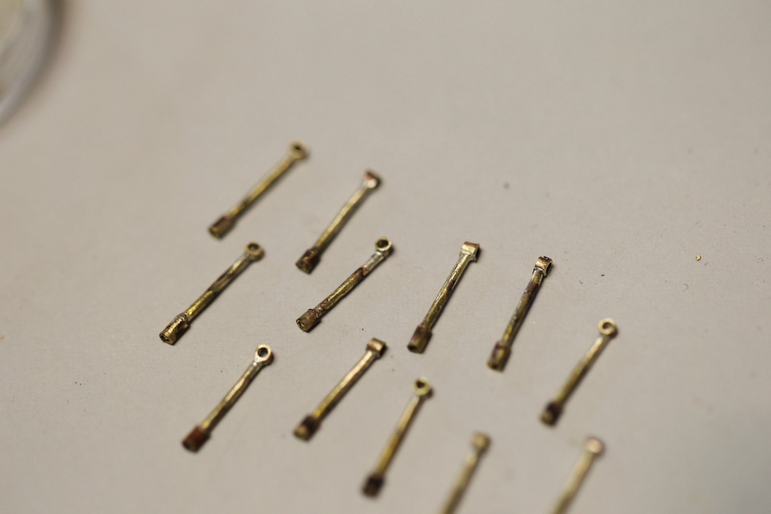
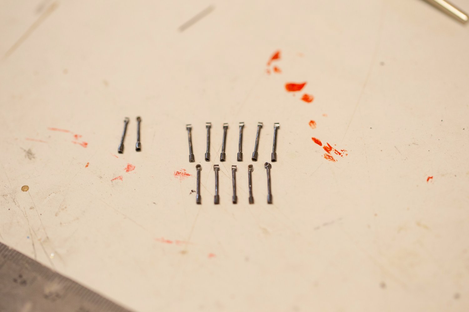
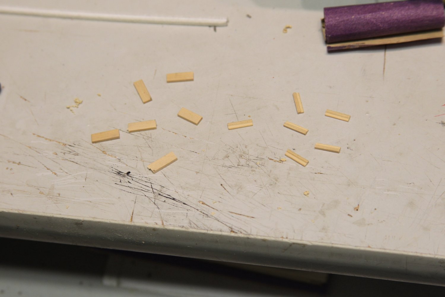
Stanchions first. I cut fourteen 1mm tubes and twenty eight 2mm tubes (two for each stanchion). The 1 mm tubes will insert into the 2mm tubes to create the wider portion at the bottom that then plugs into the railing. Another 2mm tube is soldered to the top of the stanchion as the eye through which the cable will pass. The top tube is soldered on larger, then filed down to be almost even with the stanchion, after which everything is blackened.
Note: Trying to hold these things in place to be soldered took some ingenuity, extra clamp hands, and locking needle tweezers. During this process, more than a couple of these little escape artists went flinging across the room never to be seen again.
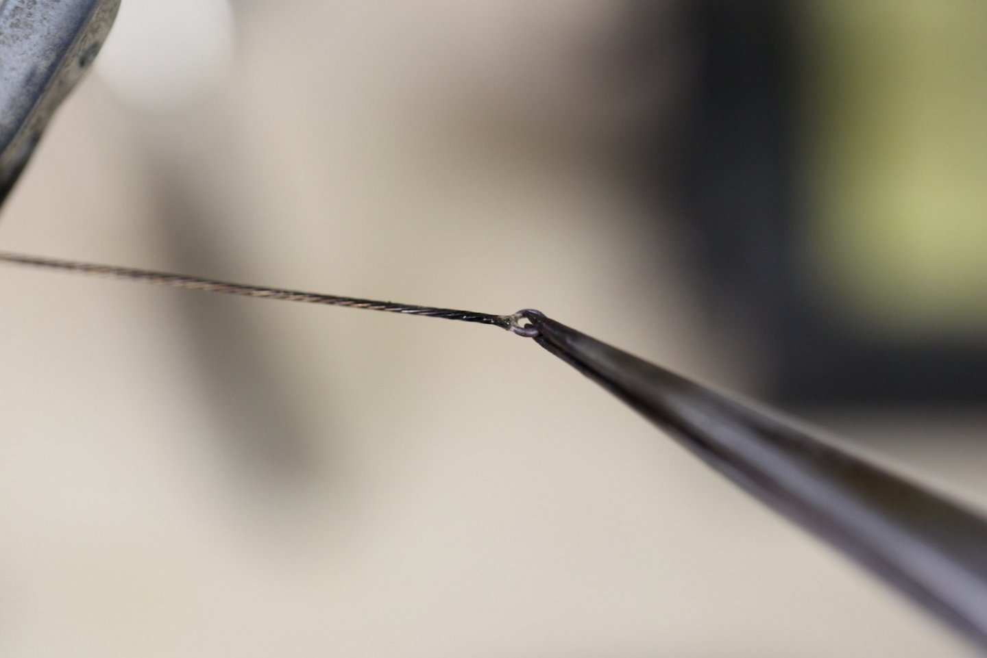
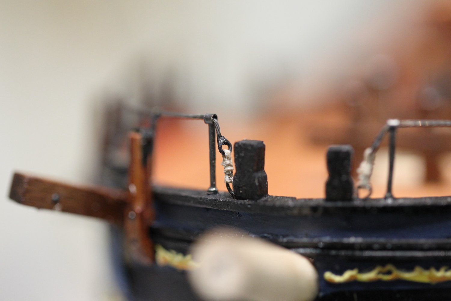
I soldered a ring on one end of the cable and an eye bolt onto the other end. Here was a trick - I wanted to make sure all the stanchions lined up properly in terms of height, distance, etc - and then make sure the cable was the exact right length. I couldn't just cut and tie it like a rope, so I had to pass the cable through the stanchions after they were mounted, measure the distance of the cable, then solder the eye bolt on the end of the cable while it was on the ship. Obviously paranoid about burning the ship up in a giant ball of polyurethane and wood flames, I used a piece of metal to block off everything that wasn't being soldered. Very tense process - wish I'd have been able to take a photo of it whilst I was doing it.
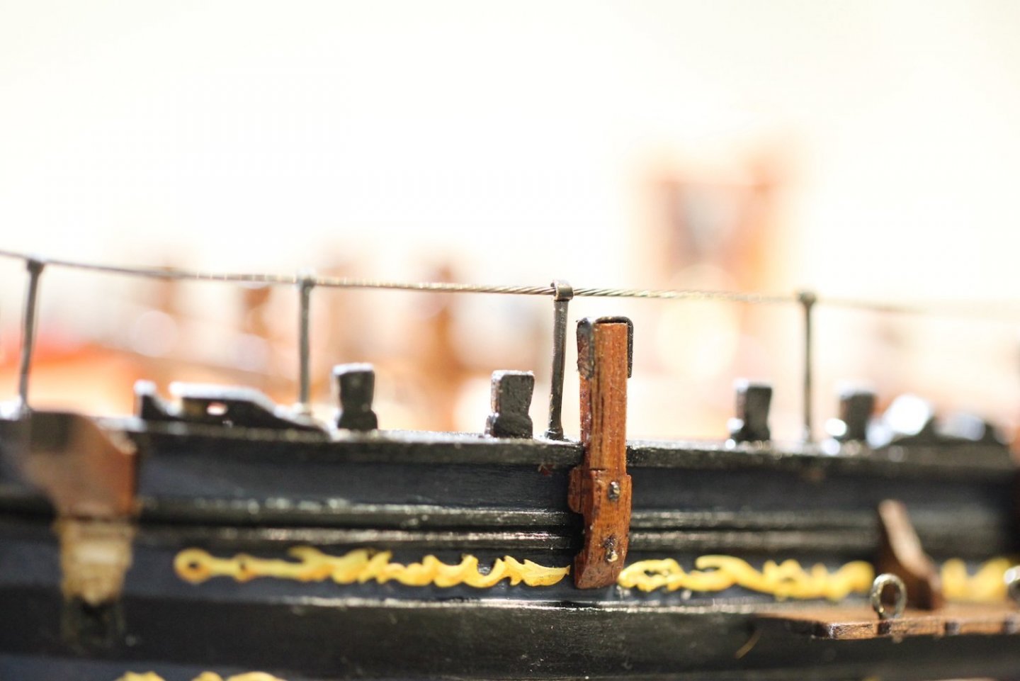
The bow end of the railing is seized just as though it were a rope, and the waist end of the cable is mounted into the railing with the eyebolt.

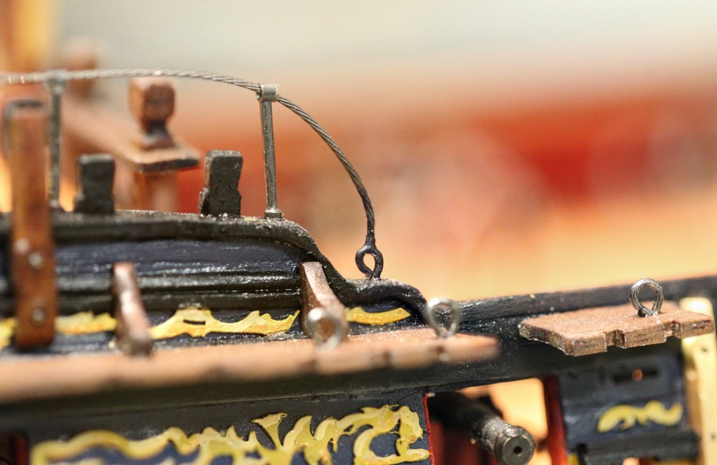

Once again in the "joys of macro photography" category: is everyone else's ship THIS dusty? It's kinda yucky seeing every little grain of dust. I mean, I try to tidy up pretty often...
-
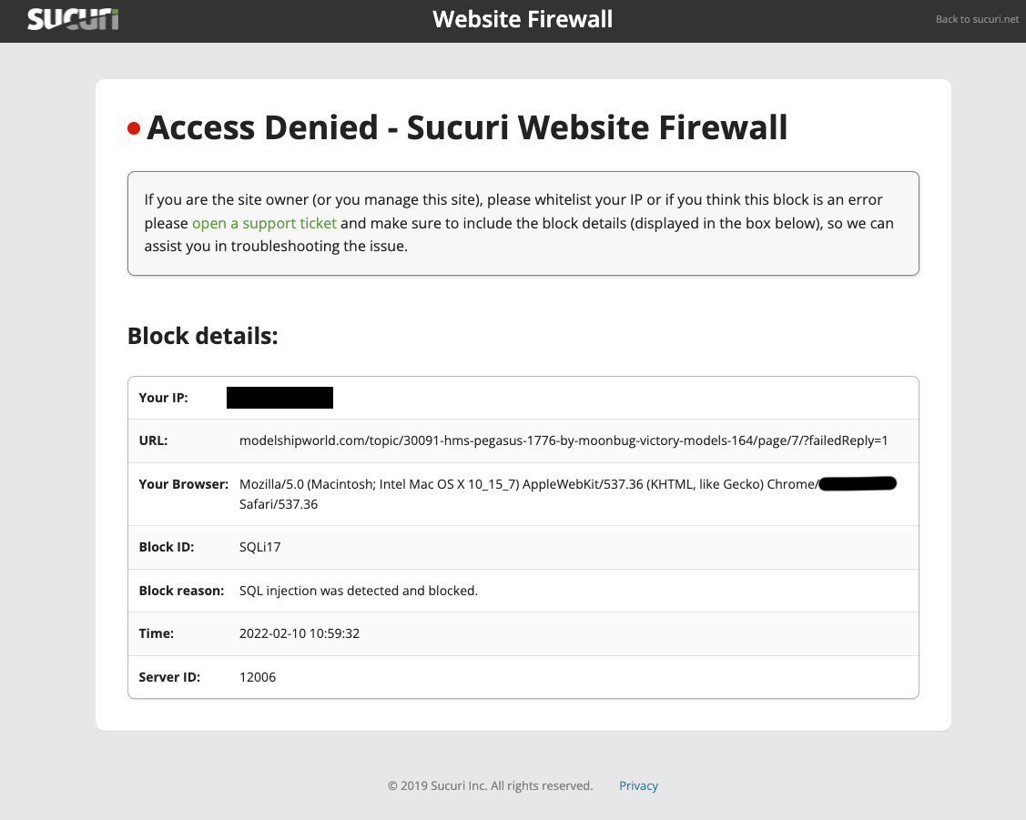 Anyone else getting this error? Never had it happen before - and now it's cropping up quite a bit. Very frustrating.
-
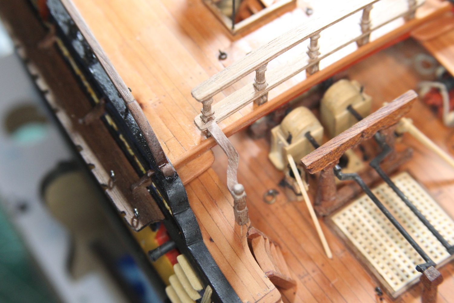
Under the “re-do” column:
The photos of the breastwork
pointed out some things I didn’t like about my cistern pumps. They were made early in the build before I upped my blackening game - and had a fair amount of paint touch ups, etc.
Though they were “alright” they started bugging me like the stove vent: So - risking much peril - I spent a few hours yesterday and completely pulled them out, sanded down all the metal parts, re-soldered some, and re-blackened all the brass including the brackets and stops.
-
-
-
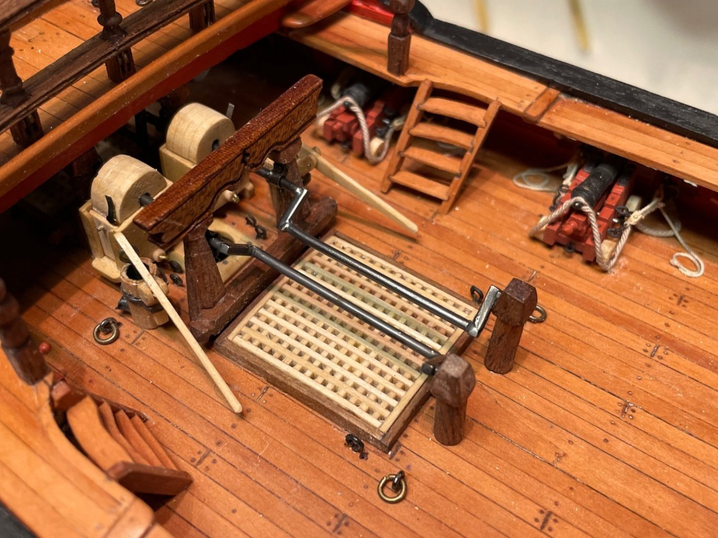
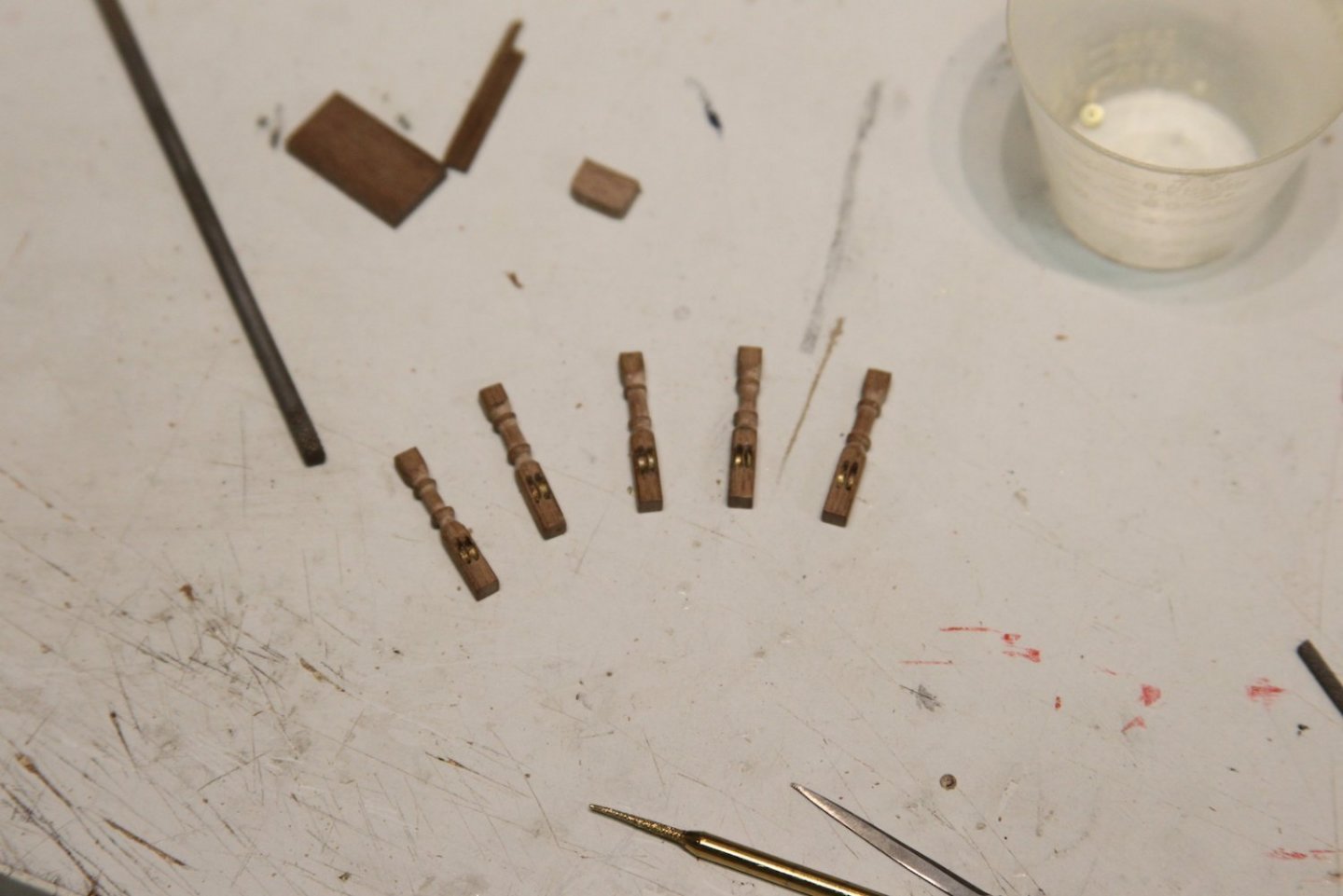
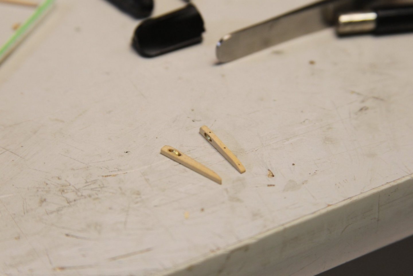
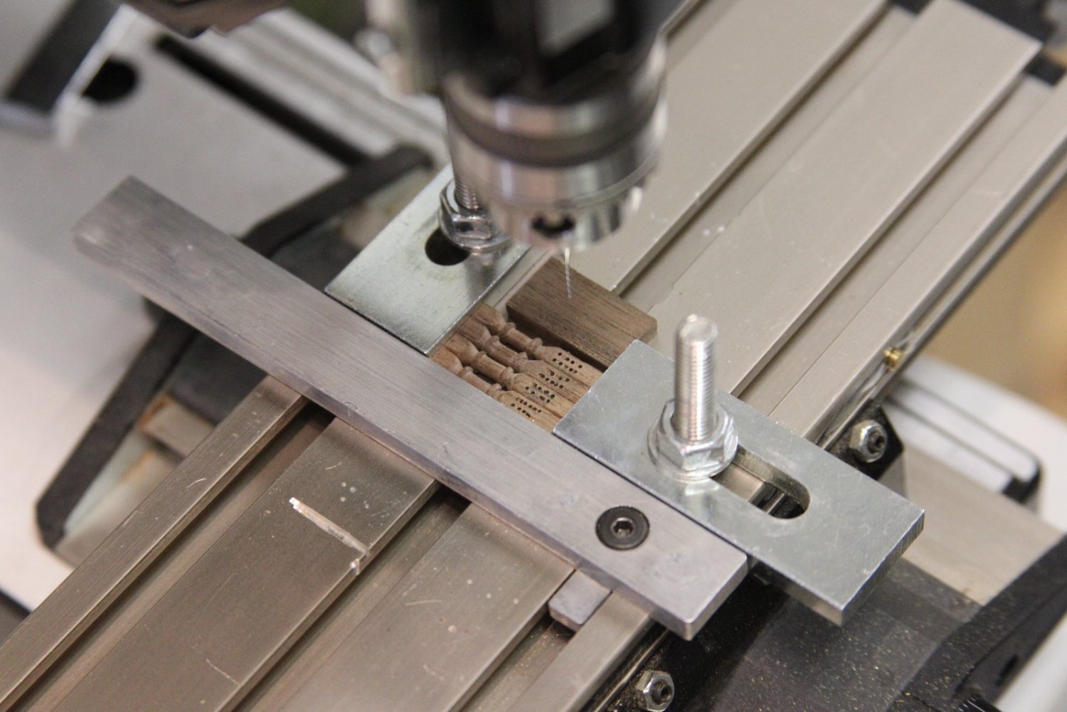
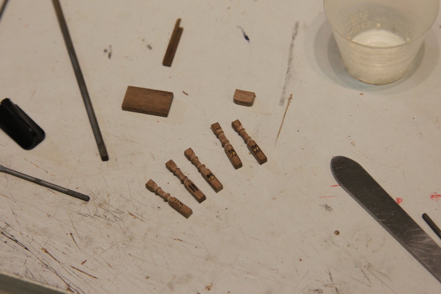
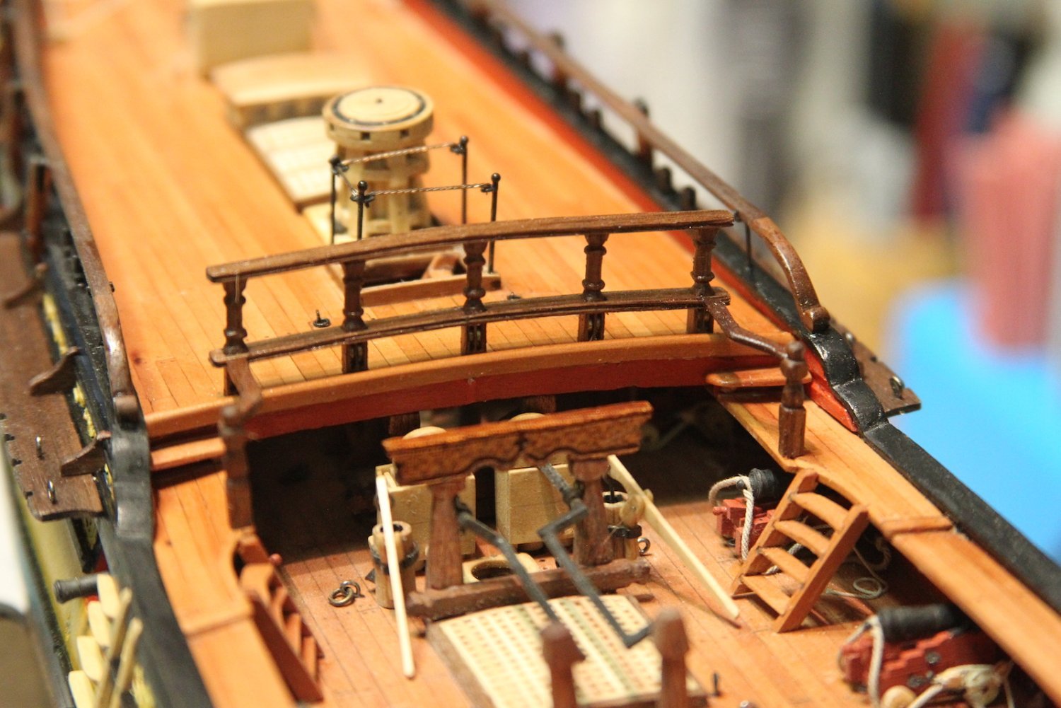
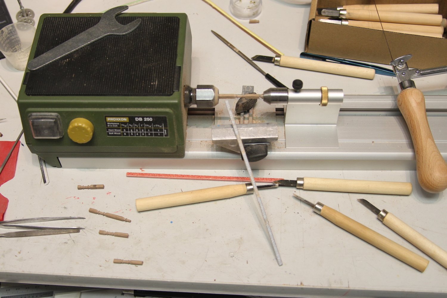
The breastwork on the quarterdeck is pretty similar in terms of how it's accomplished. First step is to turn the stanchions on the lathe. The tricky part (as I mentioned) is that these are double sheaved instead of single singled. I'll tell you, at 1/64 that's a real bear. The actual metal sheave needs to be so thin (less than .5mm) that there was just no real way I could notch it small enough - so I gave up on that and settled for just having the ring in the slot - so to speak. Creating the slot started with drilling holes in line, then picking them out gently with a #11 scalpel as much as I could. Next, I shaved down my smallest needle file to almost paper thin so that the grooves were only on one side and one edge. Finally, I gently filed out each groove a tiny bit at a time.

The sheaves are cut from a 2mm metal tube filed down on each side until they fit into the slot. The slot determined the size of the ring, not the other way around. File - test fit - file - test fit, etc. Here's a progression of what that looked like. Each stanchion took almost 90 minutes to get cut and grooved out. Sorry, the focus isn't great on these two. Probably because I was cross-eyed from filing out the grooves.

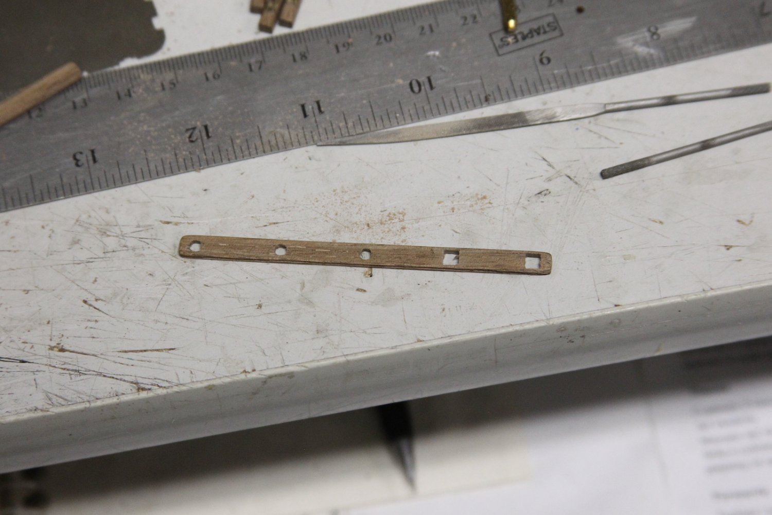
I took a different approach for the railing this time - instead of two pieces, I measured out a single piece with about .5mm overlap on each side of the stanchion and cut square holes to fit - starting with drilling out a hole then filing with a square edge needle file. This took much longer than the 'two piece' method, but eliminated the very slight line you can see in the forecastle railing. The edges of the railings were scraped for a little decoration.

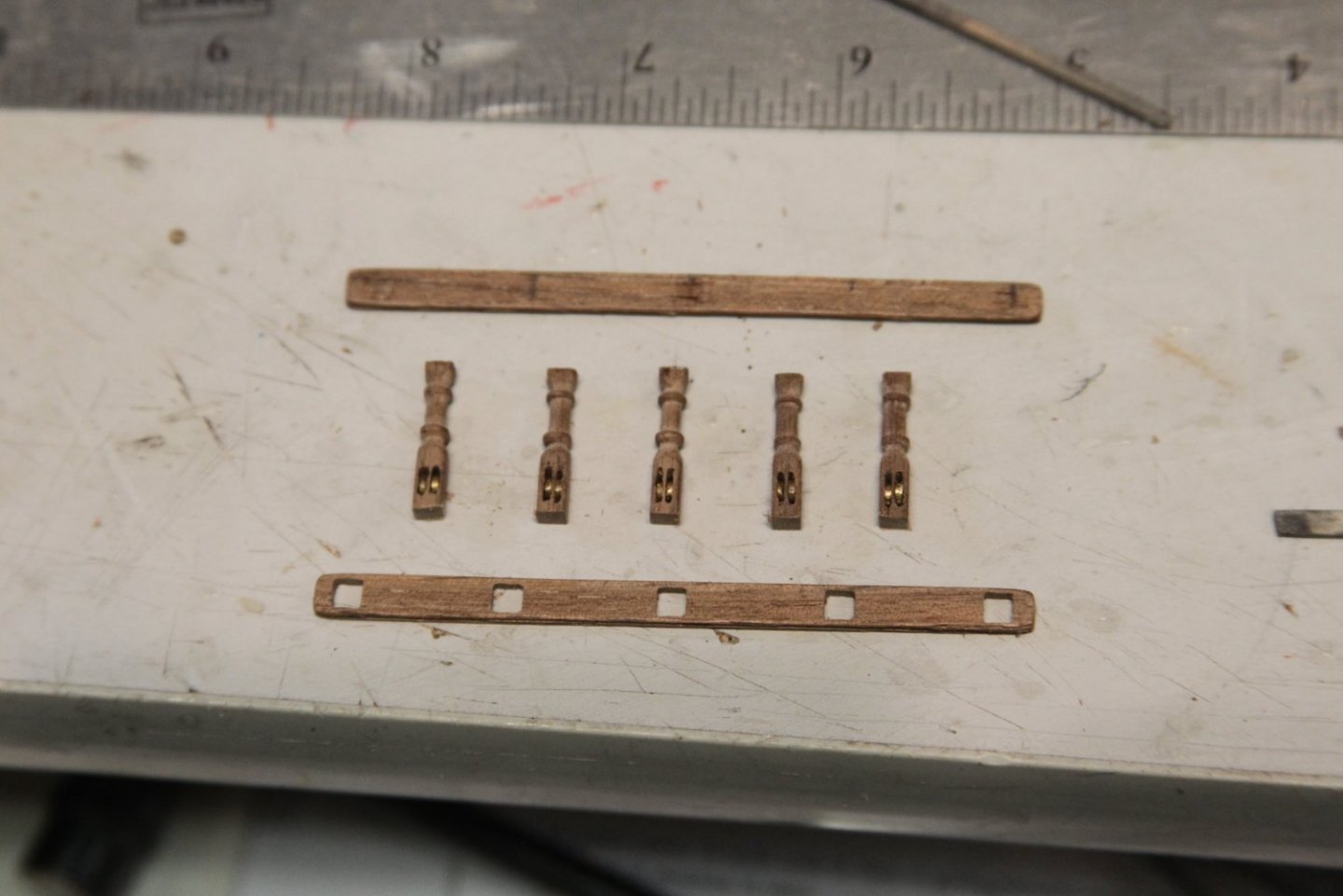

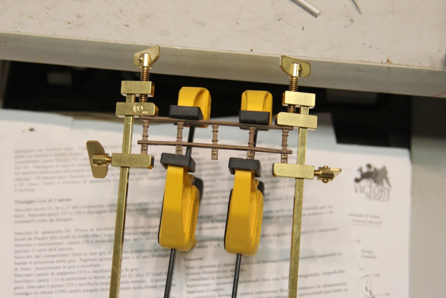
Gluing it all together was a trick. And yes - I noticed the middle stanchion was crooked upon taking the photo (ah, the joys of macro) and fixed it.
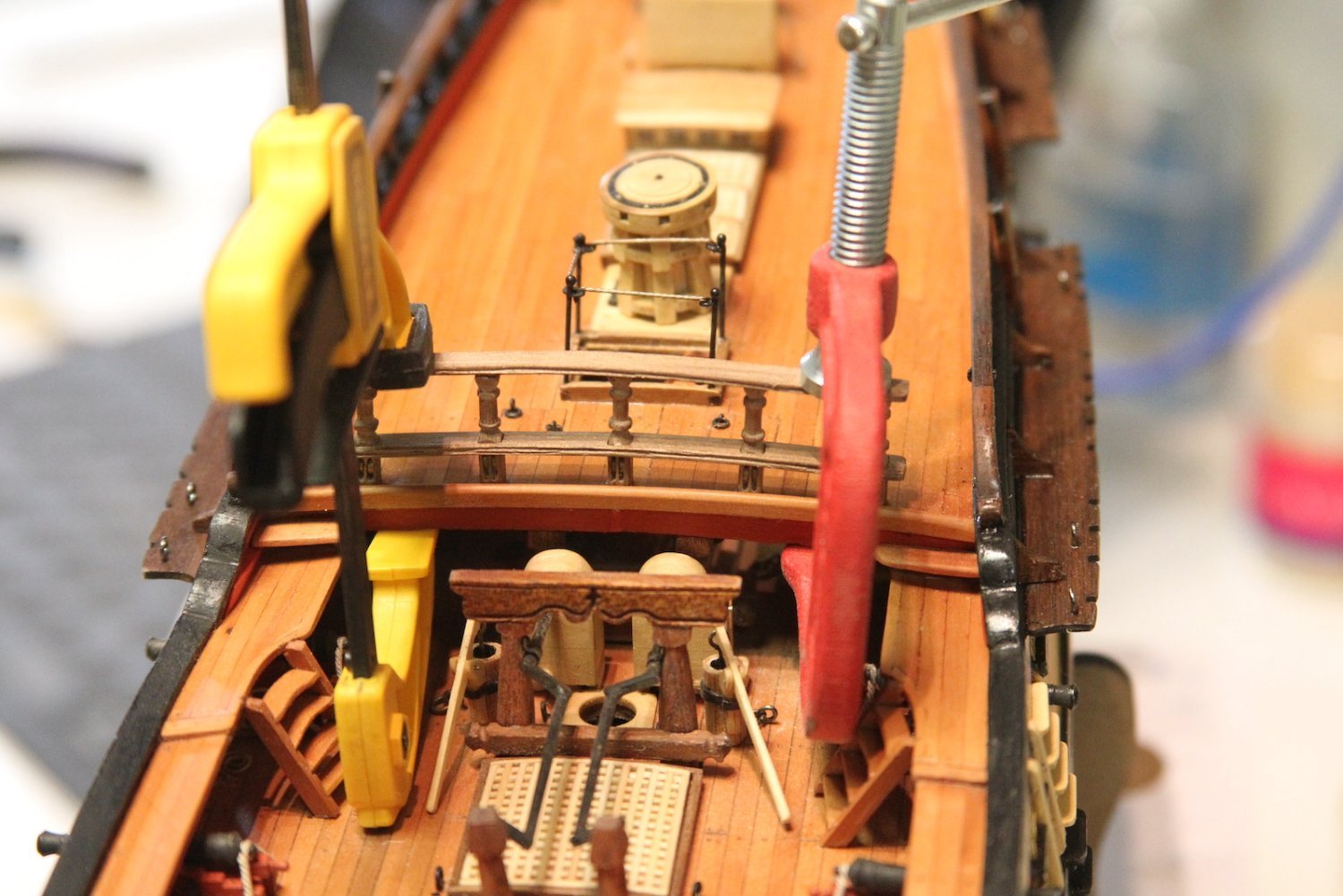
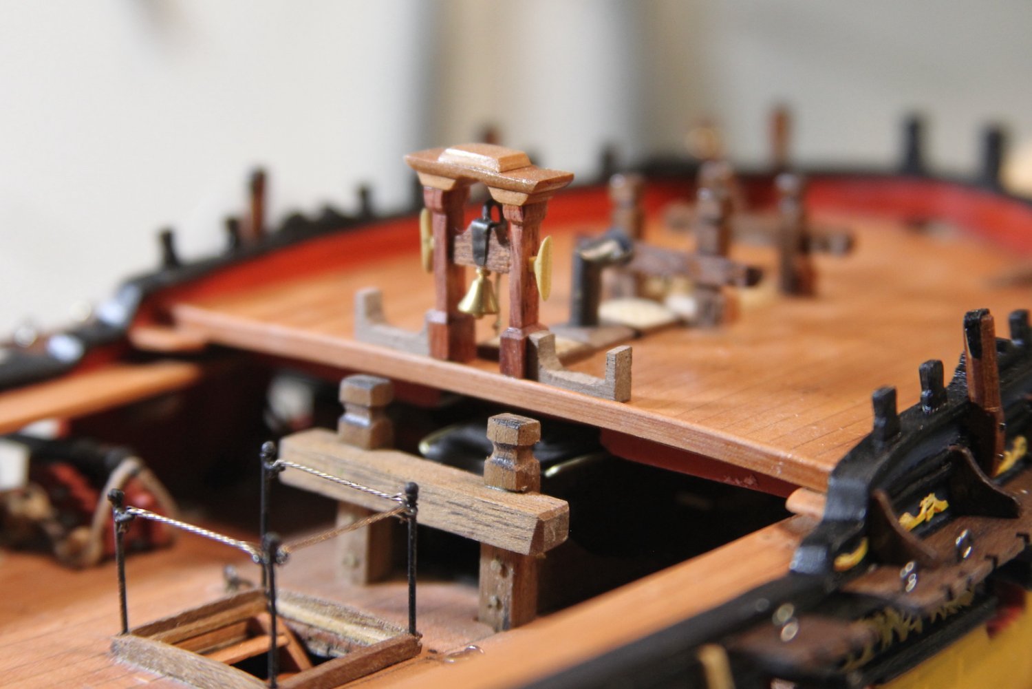
The railing is mounted on the deck and follows the shape of the deck. Good thing I had to fix that middle stanchion, because after the railing is placed on the deck, the bottom rail sits a fraction higher on the middle post. It was helpful to dampen the railings as I fit it to the deck - even so I was anxiously anticipating the whole thing to crack as I bent it. I also added a pin in the middle stanchion as I affixed it to the deck to hold the structure it in place while I clamped it down.
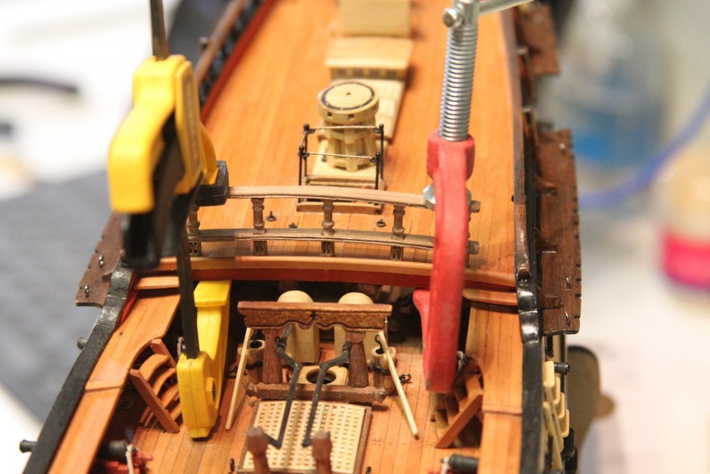
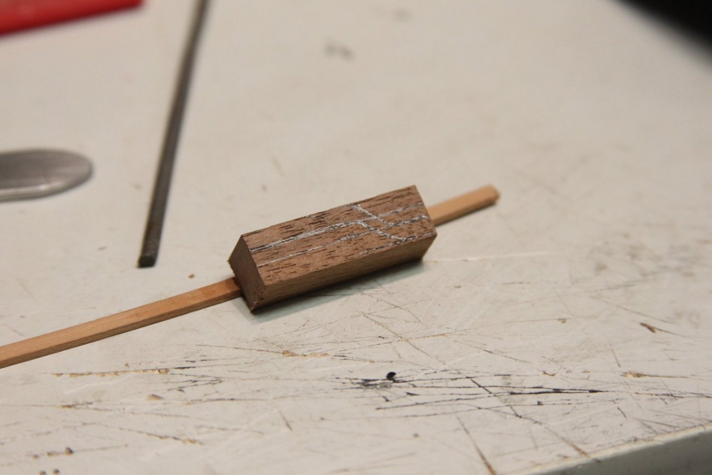
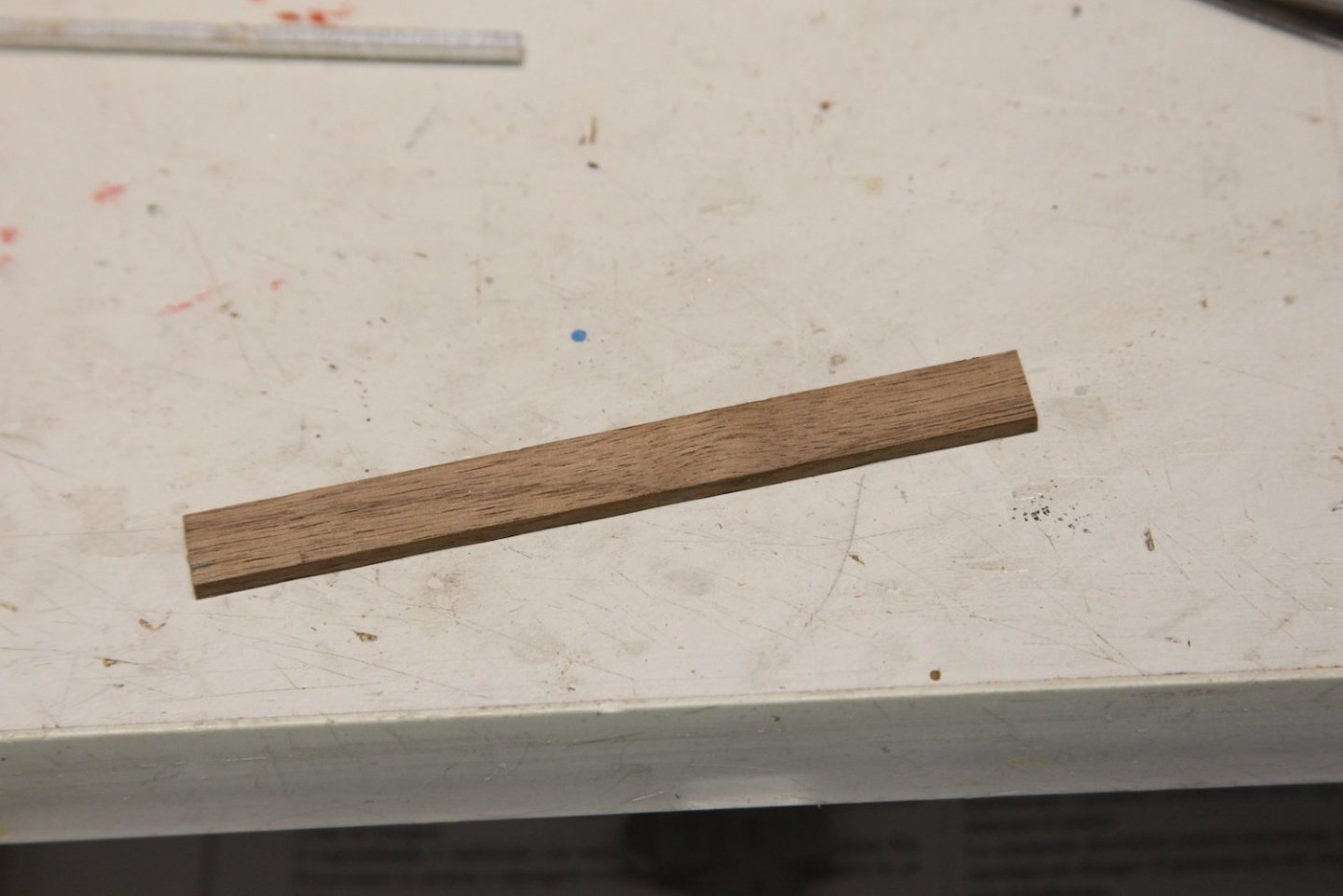
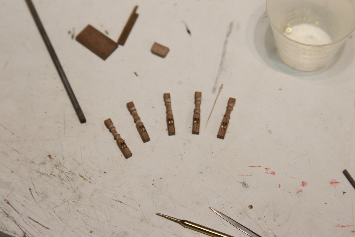
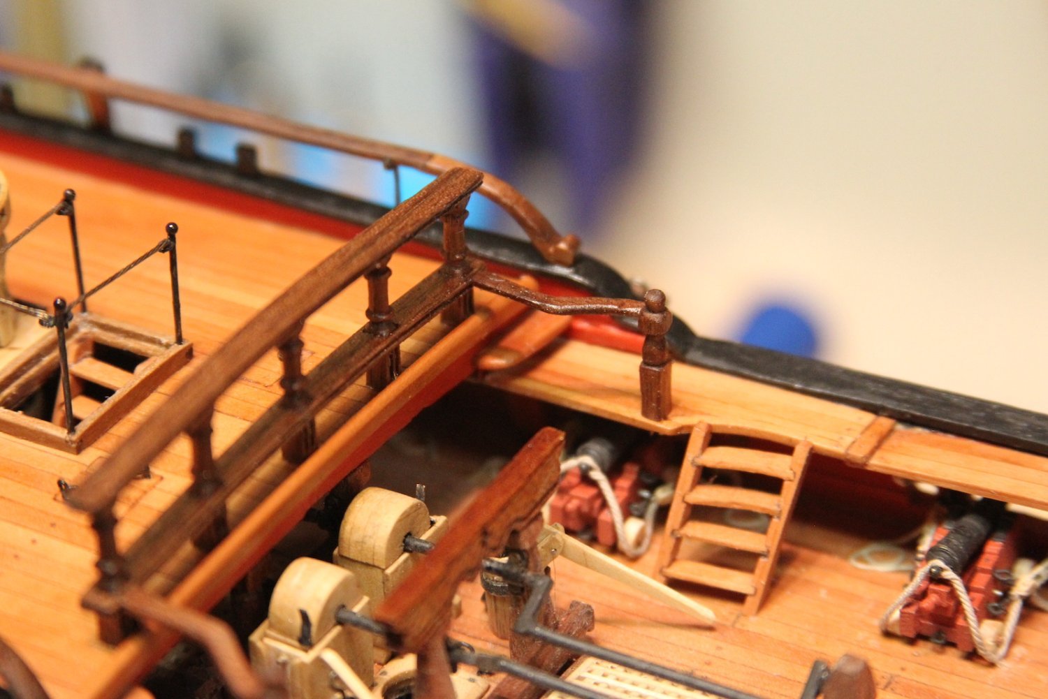
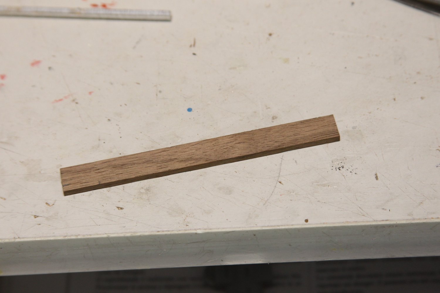
The railings are extended to the gangways with two more stanchions and extended railings with an "S" curve to them. The stanchions are turned on the lathe with a little round newel post top. The railings are cut from a single block of Walnut. I cut them out with the jigsaw together to ensure that they mirror one another, then after the shape is sanded I split them into two railings on the Byrnes saw.

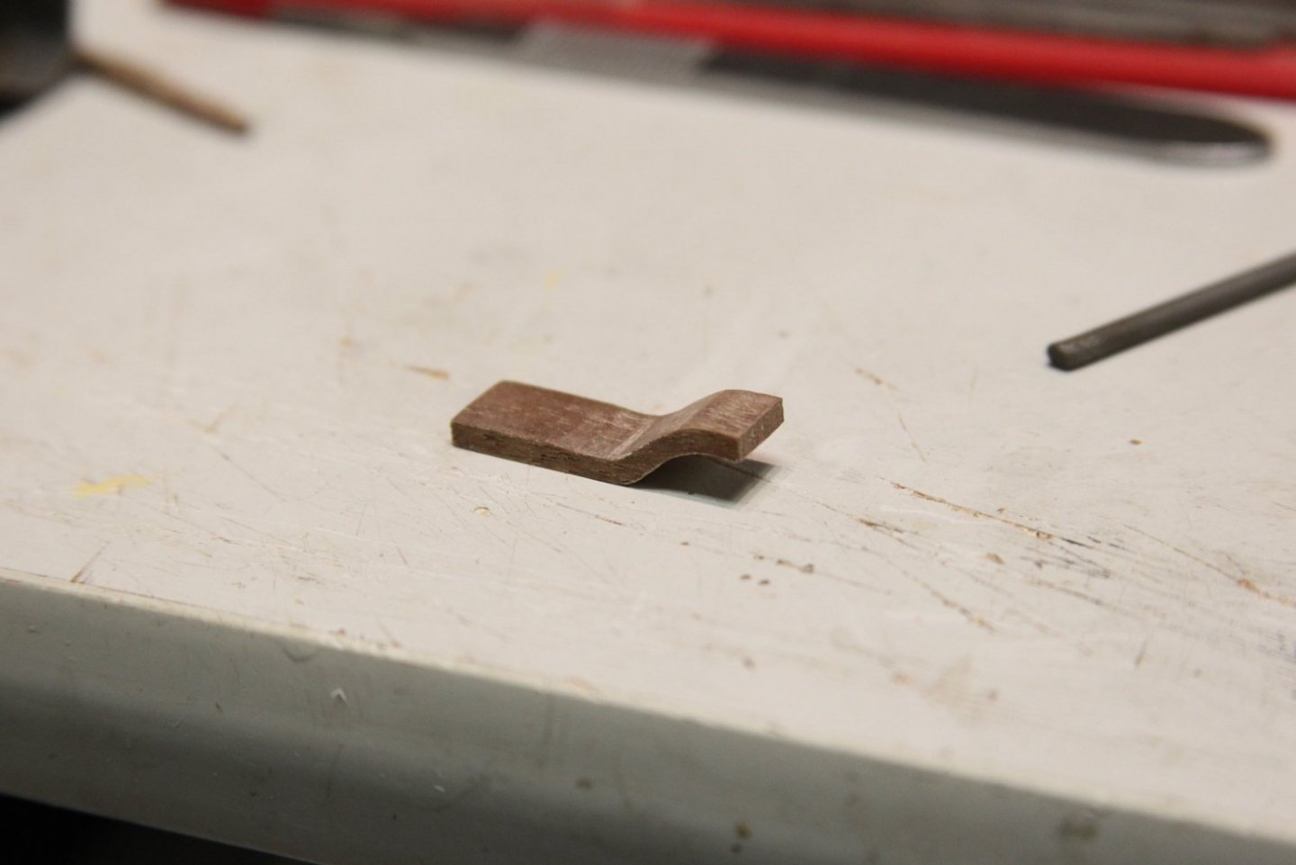

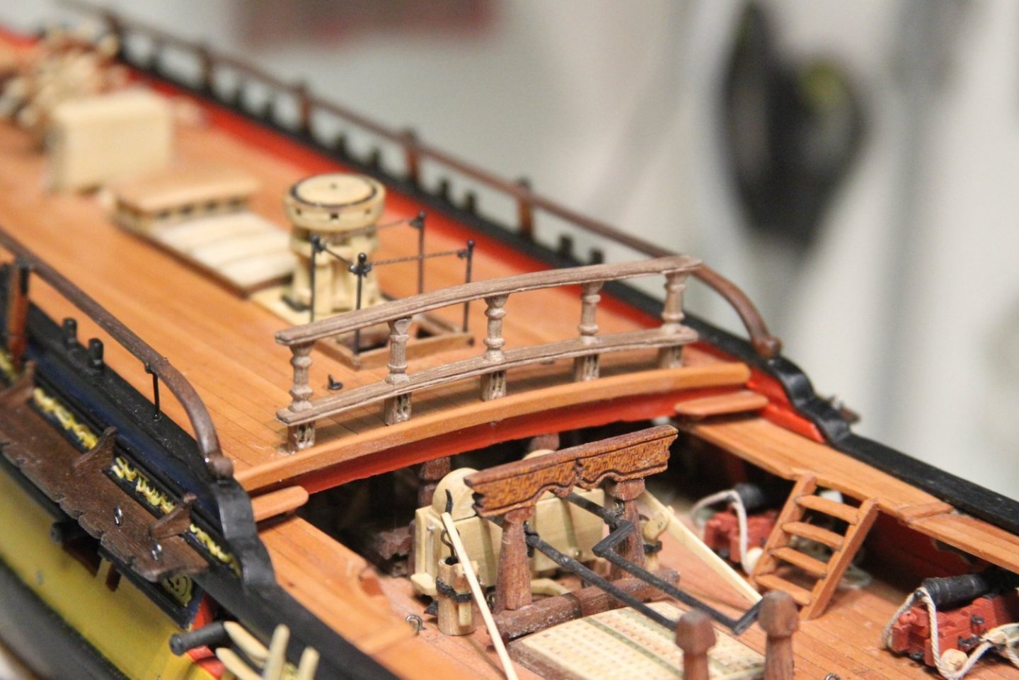
From there it's the fit-sand-fit process until it's snug. After everything is fitted and glued, the edges are all gently sanded and smoothed out and the whole thing is given the Tung oil treatment. Overall, I'm pretty stoked with how this turned out - especially at 1/64. The FFM shows an additional decorative metal piece that connects the upper railing to the gangway railing - however, if we remember; my drop to the gangway is an an extra step because of the thickness of my Swiss Pear decks - so that extra metal piece just looked funky and out of place. I fit "Lawnmower Man" for scale, and it all looked functional, safe, and viable - so I left it well enough alone.


-
-
As a side note: I've been following a few of the Winnie builds - and this is one of the first photos I've seen that really shows the scale of that thing. That's a big boat!
- FrankWouts and Mldixon
-
2
-
-
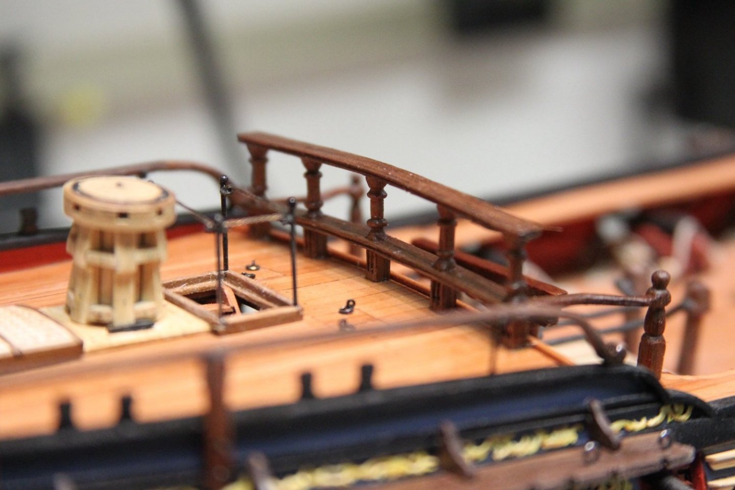
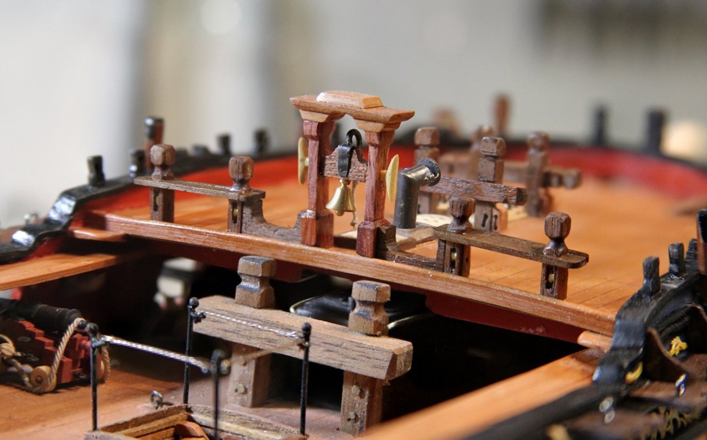
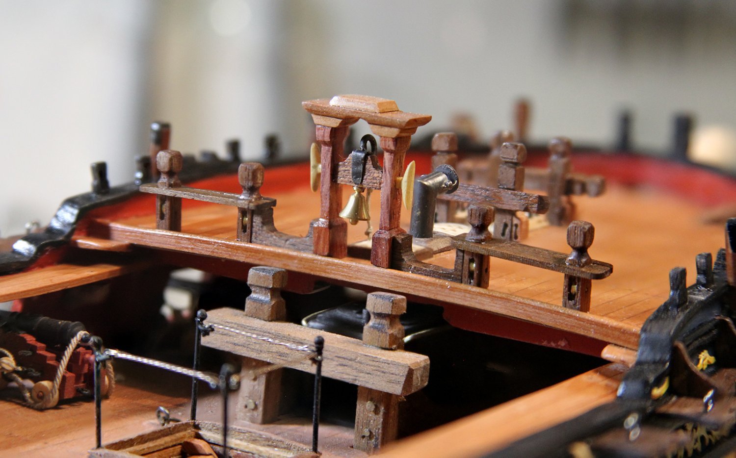
I spent much of the weekend working on the forecastle railings and the quarterdeck breastwork. It's a fun endeavor and I'd been looking forward to this and testing my skillset patterning the work after the FFM and the other builds to which I most commonly refer. I'll preface by saying the railings and products that are supplied by Chris' kit are just fine in this regard - however, I'd already committed myself to using walnut for the other railings, bitts, crossbeams, etc. Once again, since I'm being sparse with paint, I want everything to match - or at least compliment.
Unfortunately, we know that walnut - though prevalent in my wood pile - is not the densest wood for carving, but it is pretty malleable for shaping, etc. They'll be two separate posts here, but I essentially worked on the forecastle and quarterdeck railings simultaneously, as both required turning the stanchions on the lathe and create the sheaves.
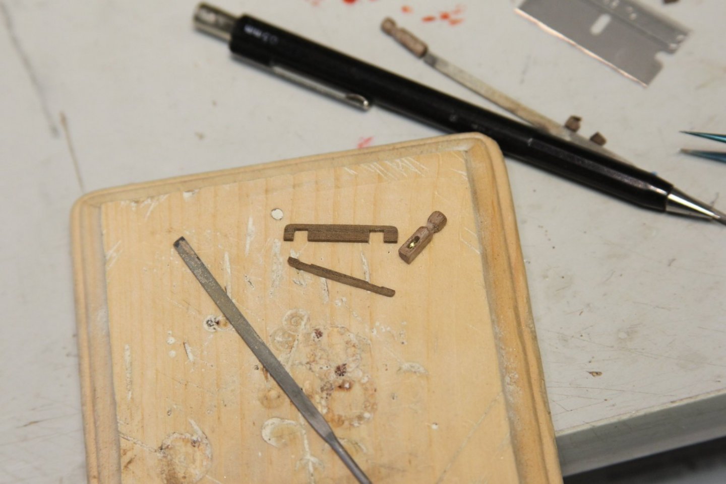
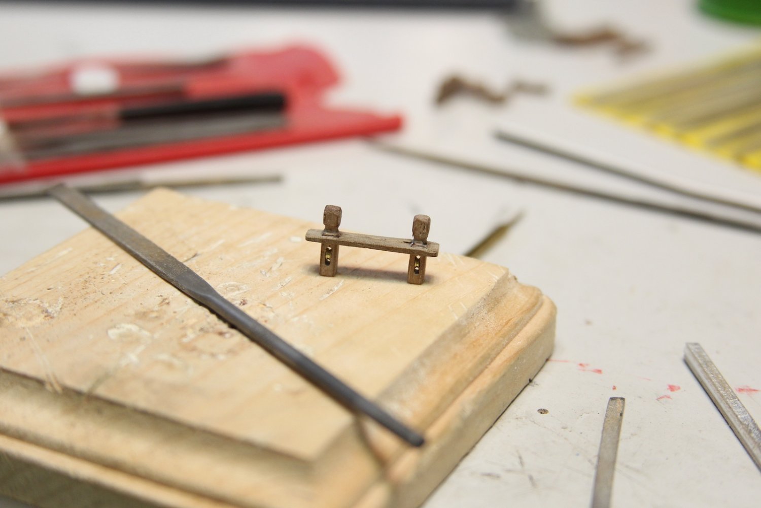
I started with the spar rack, just a couple of pieces cut with a jig saw then sanded and shaped to fit the height of the Belfry stanchions just below the cleats. They're the same width as the rails with the inside post shaped to fit snug against the belfry and the outside serving as a base for the railing.

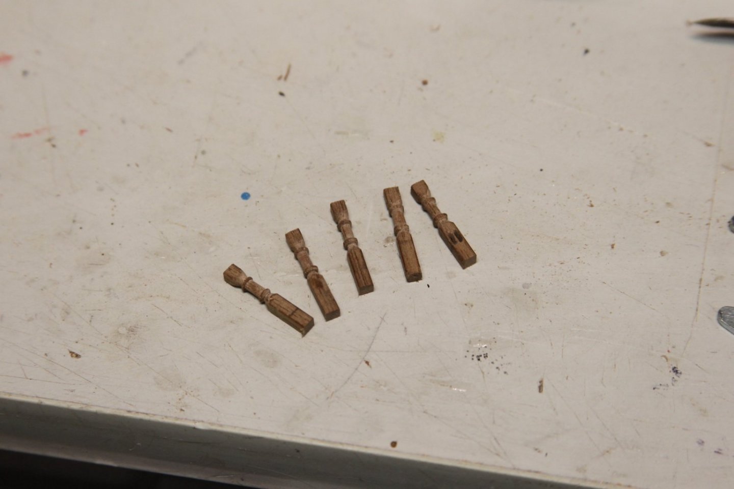
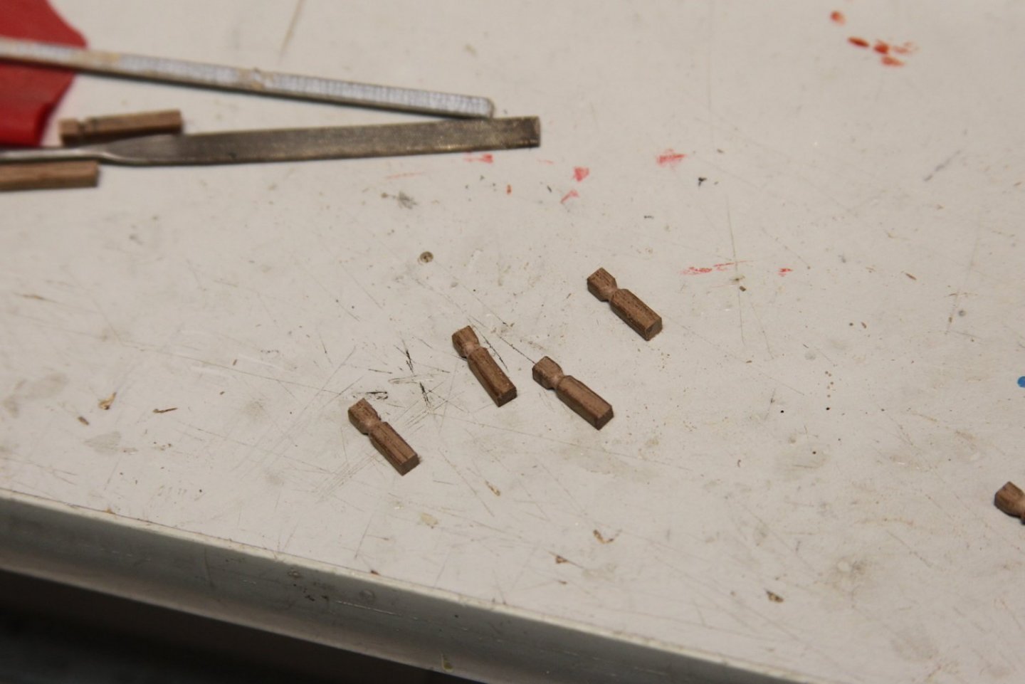
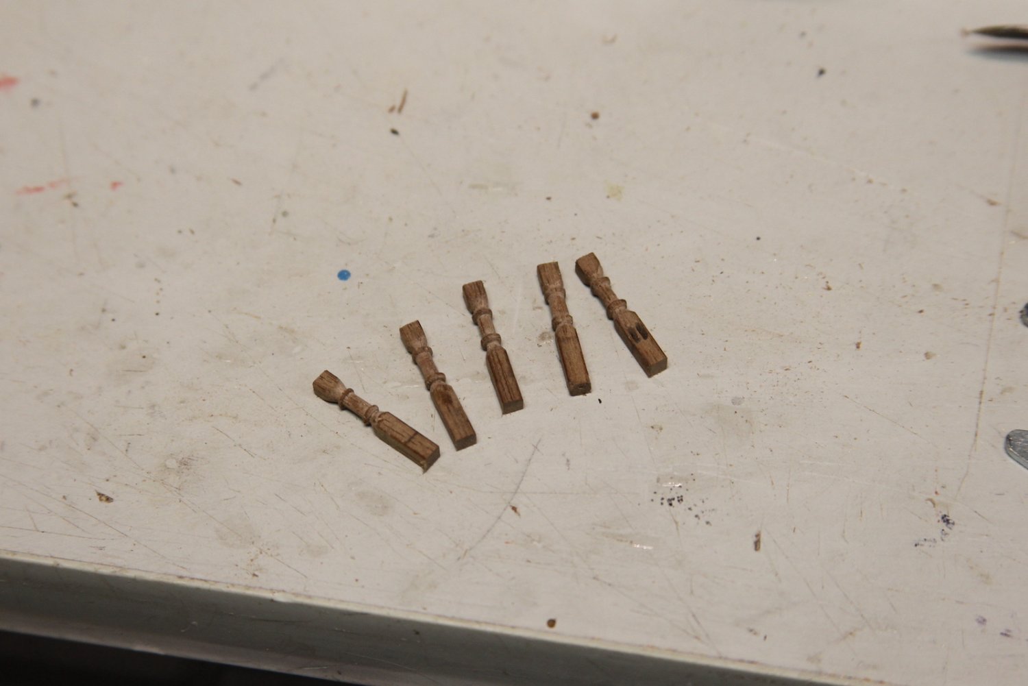
Stanchions are turned on the lathe with a little bit of decorative element. I had to keep it pretty simple because the walnut has a tendency to flake of course. I included the first picture because it took me several experiments using a variety of options before I found what worked for me and didn't either flake off the post or snap it completely. My rather cheap carving tools are regularly sharpened on the belt sander before I use them. Essentially I use a file to get started, the carving tools to shape, and then a sanding stick to smooth out the edges.

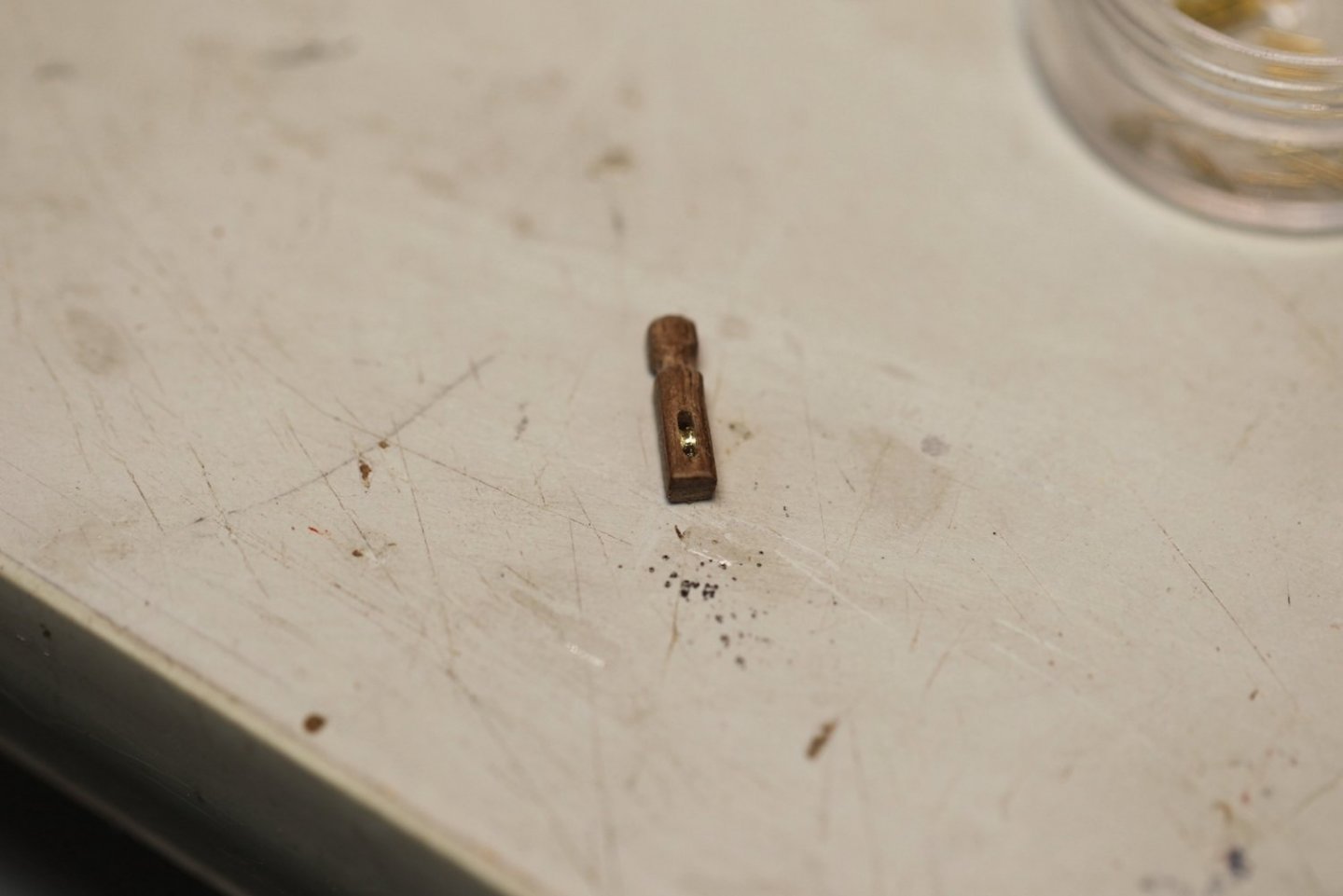
For the record - I had totally convinced myself that it was fine to just make faux sheaves here, especially since they're under railings and difficult to see. Then - for whatever masochistic reason - I decided that I should go ahead and make sheaves; which as you might imagine is completely torturous at 1/64. And yes - I am totally convinced this is going to bite me in the a** when it comes time to actually try and rig the thing. But, in the meantime, I think they look pretty good.
For the forecastle, I took Mr. Vadas' idea of splitting the railing itself into two pieces to facilitate mounting it with the stanchions. This worked well, but required lots and lots of patient bit-at-a-time sanding to get everything line up properly and fit snug. You'll see later that I took a different (and ultimately more tedious approach) on the quarterdeck breast work.
Stanchions and railings are mounted after a lot of test fitting and tiny adjustments with a sanding stick. Then everything is sanded smooth to get as tight of a fitting as possible. Still a couple little gaps that will get masked with the finish.


Once permanently mounted, a coat of tung oil is applied to match it up to the other walnut pieces.
-
-
-
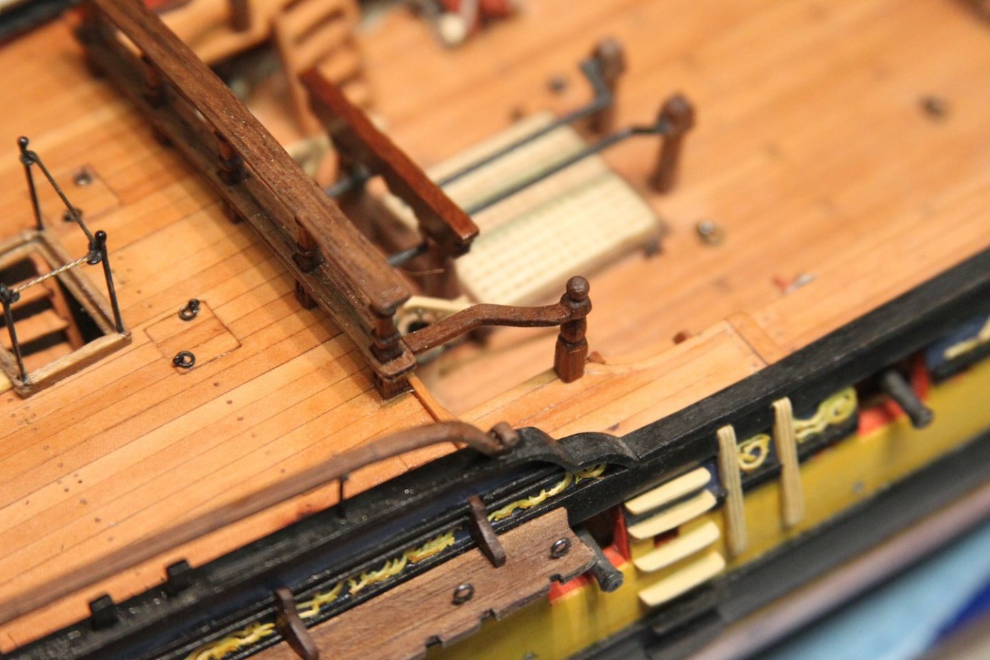
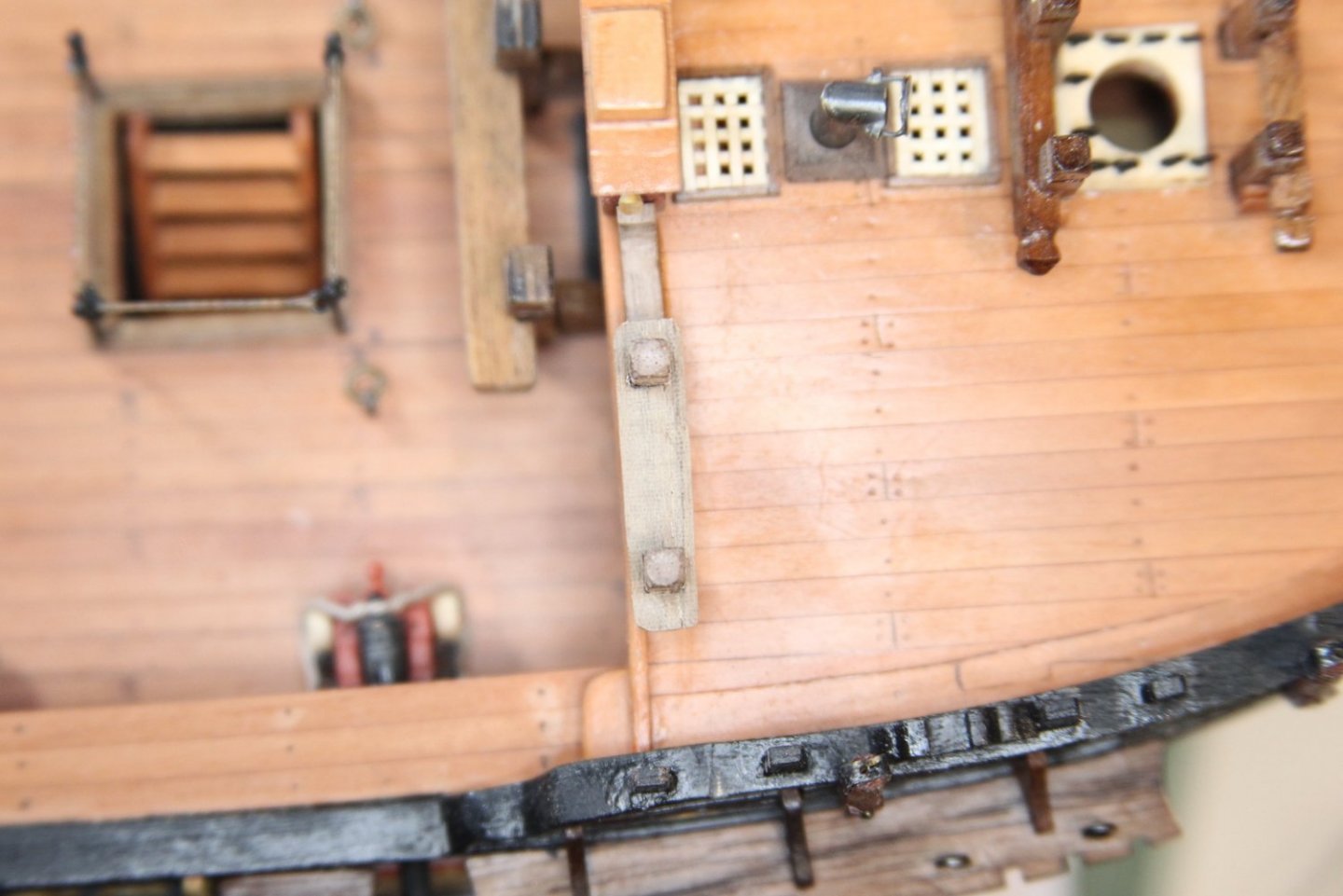
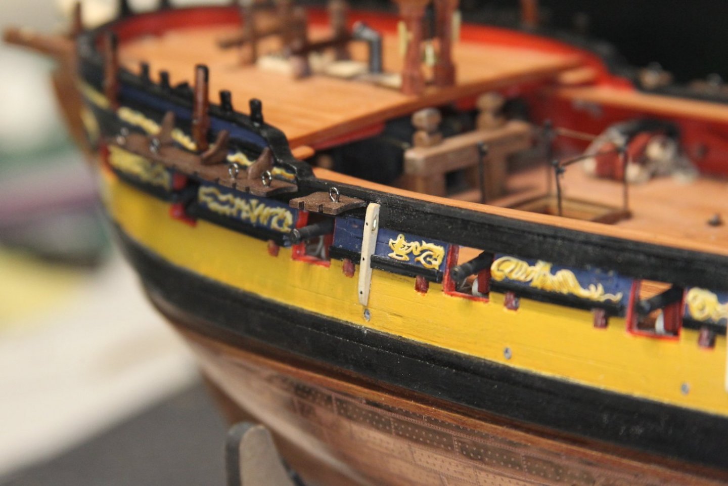
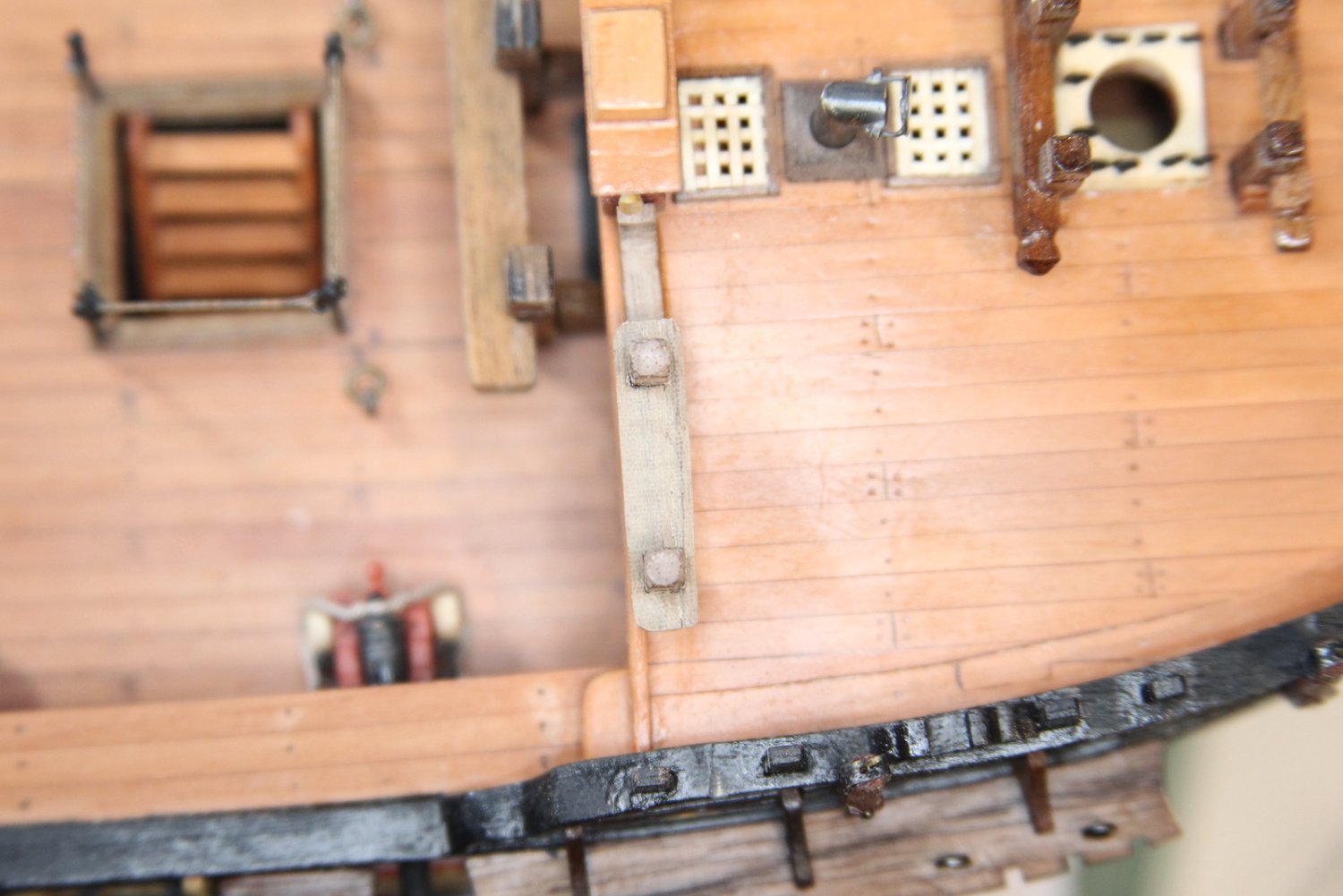
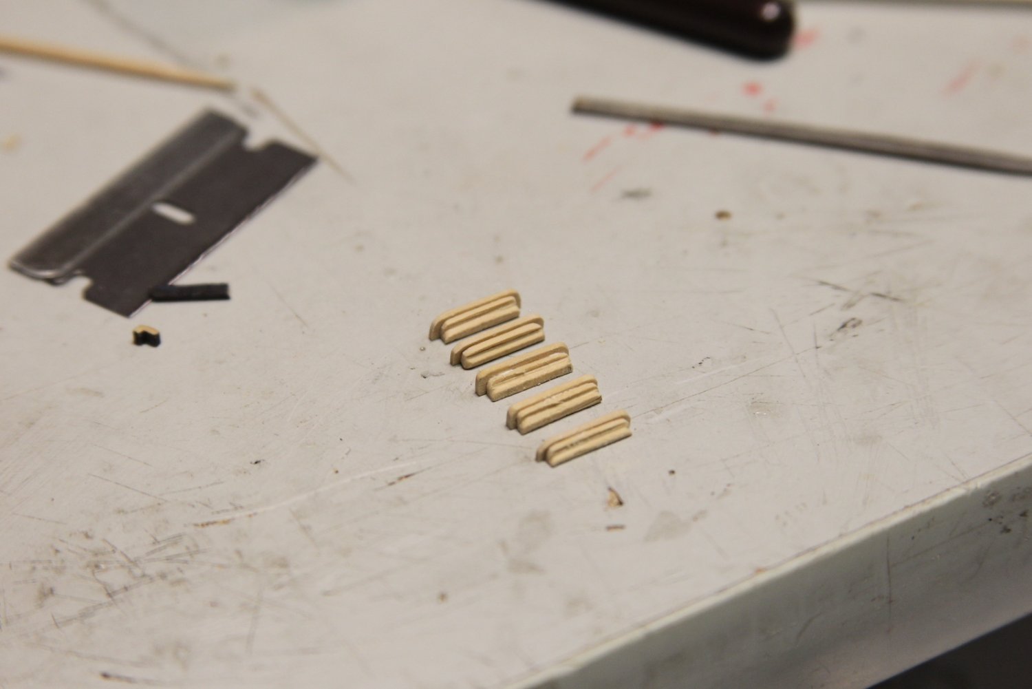
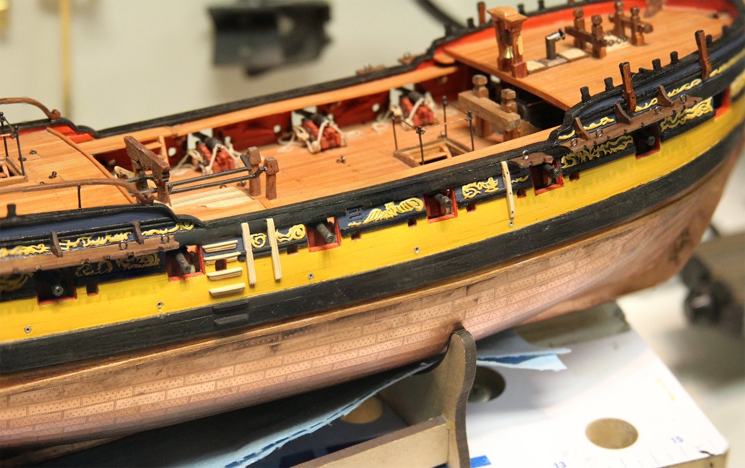
Did some work on the outer hull fixtures during the week. See - the thing is - I thought these would be pretty straightforward, and they turned out to be pretty fiddly. Here's what I'm learning as I pattern much of work after Dan's Vulture - that stuff looks pretty complicated at 1/48 - then I try to replicated it at 1/64 and it's just madness. Alas - I'll keep plugging away; but I'm definitely going to have to start determining what's just unfeasible at the smaller scale.
The steps are made from two separate pieces of boxwood fit together to create the decorative element. The smaller of the two pieces is cut with a scraper then glued to the 'step' portion. Each step is mounted to the side of the hull with the middle one cut out to provide for the sweep
port opening next to the gunport. I couldn't quite figure out what to do about the rail that runs through the gun port, so I just removed it and replaced it with the step. The bottom two are painted black to match the main wales.


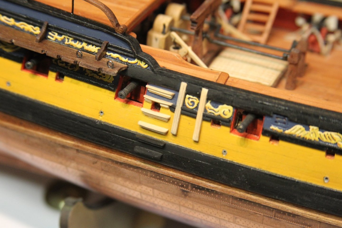
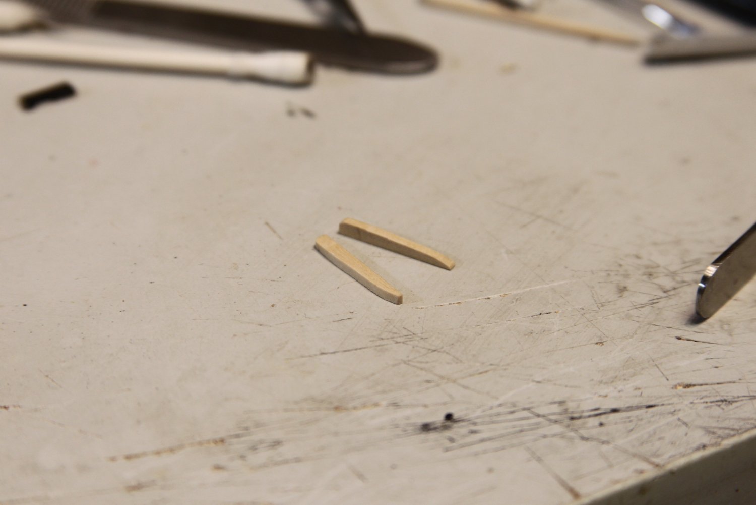
The fenders (already mounted in the picture above) actually were pretty straightforward - a couple strips of boxwood scraped for decoration and fitted. I did have to move the frieze around to accommodate.
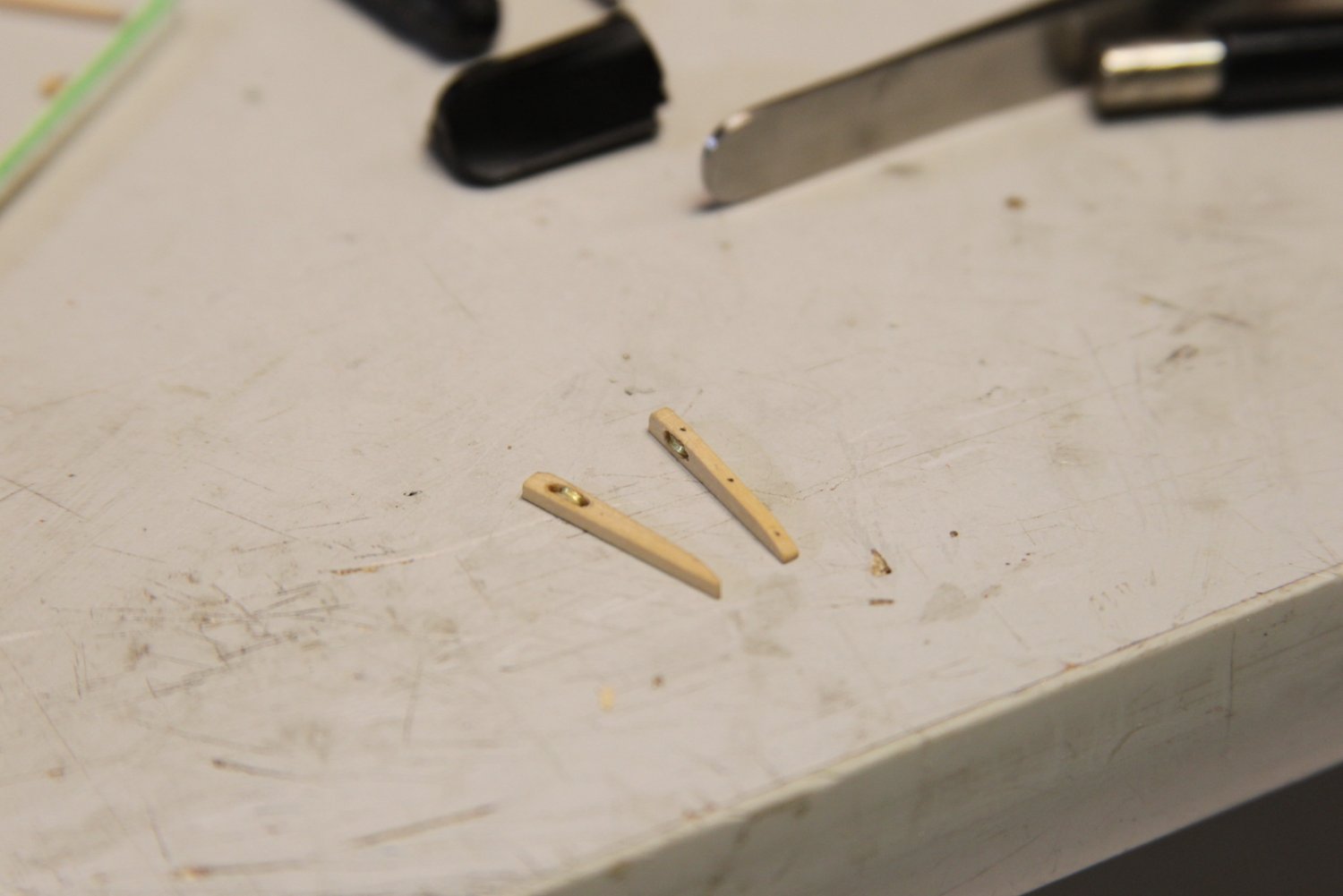
The chesstrees were very sketchy. I really wanted to just do a faux sheave, but it would not have looked that great. So I gave it my best shot the same way I did with the catheads. Much less space to work with however. Mounted up just aft of the fixed block.


As a side note - the last image is a good example of how I often focus stack my images. I use a couple different lenses - one is pure macro (100mm f2.8) and one is a short zoom with a little more flexibility. But if you're able to focus stack, it's pretty helpful. There's a good discussion about it here in the forum:
- AJohnson, chris watton, gjdale and 4 others
-
7
-
-
Hey Mark - we’re here with you when you’re ready to return. I get it with the eyes - I just ordered some surgical loupes because I can’t see crap any more these days. 😕
Good luck friend, and don’t be a stranger despite the pause.
- Dave_E, Edwardkenway, bruce d and 7 others
-
10


Rope making attempts - Feedback requested
in Masting, rigging and sails
Posted
Thanks Chuck - much appreciated. Still getting a feel for the tension as I walk the rope, and it's definitely easy to give it a few extra seconds with the drill "just to be sure".
And you've heard it plenty, but your rocket and instructions give newbies a great foundation upon which to work.