HOLIDAY DONATION DRIVE - SUPPORT MSW - DO YOUR PART TO KEEP THIS GREAT FORUM GOING! (Only 24 donations so far out of 49,000 members - C'mon guys!)
×


gjdale
-
Posts
4,891 -
Joined
-
Last visited
Content Type
Profiles
Forums
Gallery
Events
Everything posted by gjdale
-

The most silent disk sander
gjdale replied to Mike Y's topic in Modeling tools and Workshop Equipment
Hi Mike, I have nothing against Proxxon tools - I believe they are good quality. However, I have the Jim Byrnes disc sander (along with most of his other products), and I can tell you without hesitation that you won't find a better, or quieter, machine anywhere. It is beautifully constructed and near silent in operation. Like all his tools, it is an absolute joy to use. -
Nice to see you back in the shipyard Mobbsie. Now that you've finished correcting the mistakes of the so-called "tradesmen" in the kitchen, you can return to the important things in life!
- 1,279 replies
-
- 1
-

-
- agamemnon
- caldercraft
- (and 1 more)
-
Now that looks tricky! Nicely done Danny.
-
Nice start Danny. So glad to hear your health has improved and with a good prognosis.
- 62 replies
-
- 1
-
-
- king of the mississippi
- artesania latina
- (and 1 more)
-
Outstanding job Danny. I guess that having been paid now means that you can list your occupation as "Professional Model Builder".
-
Hey Bill, Haven't seen an update in a while. Hope everything is okay with you and that we'll see you in the shipyard again soon.
-
Fabulous Augie. You raise the bar with every post!
- 2,191 replies
-
- 1
-
-
- confederacy
- Model Shipways
- (and 1 more)
-
Nice work with all the fixes Sjors.
-
Immaculate, as always Bob. Very, very nice.
-
Right, I'm in for this one too. Who's got the popcorn and beer?
-
what is the ideal modelling table?
gjdale replied to AON's topic in Modeling tools and Workshop Equipment
Hmmmm......... Let's see now. You dropped everything to go and help your son out. Very commendable. And your son is where in the pictures above, you know, helping you out in return? What's wrong with this picture Alan? Gotta love kids............... -
Whew, that was quite a rush to get over here from your Pinnace log Mike! Okay, made it in time for a front row seat. Mark, be a good fellow and pass me a coldie and some popcorn please.
-
Did somebody say popcorn and beer? Wait for me fellas.....................
-
Lovely work Rob.
-
Gotta agree with Mark on this one Ben. That looks like my work area AFTER I've cleaned it up.
-
Hi Alan, I have both of these, as well as the saw. They do completely different jobs. I would say without a doubt that I would place the disc sander ahead in terms of versatility and overall use. The thickness sander will come into its own if you plan on milling your own timber. If you buy your timber already thicknessed, then it has less of an impact. As we are both in Canberra, if you'd like to come over and play with both you'd be most welcome. Then you can make an informed decision after using both machines. Just drop me a PM if you'd like to come play.
-
Thank you Sherry. Having seen what you have achieved so far with your gorgeous San Felipe though, I somehow don't think you'll be needing much help with your ships boats!
-
Then you seem to have learned well Sjors! Looking good.
- 1,616 replies
-
- 1
-
-
- caldercraft
- agamemnon
- (and 1 more)
-
Thanks Mobbsie, The boats will all be painted, in keeping with the "mother ship", so filler won't be a problem.
-
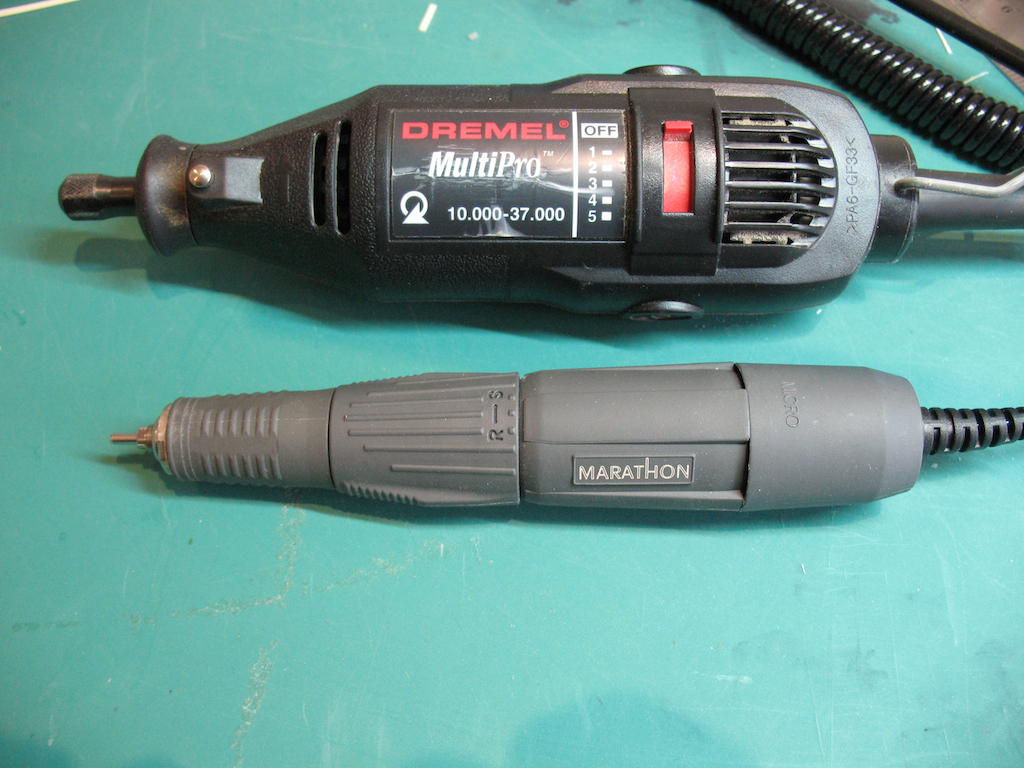
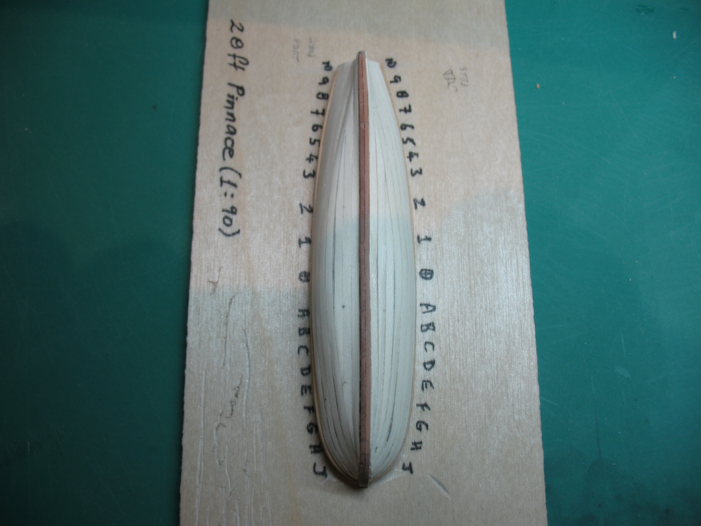
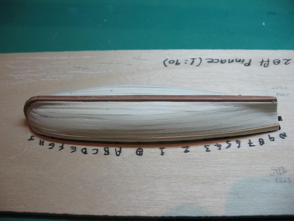
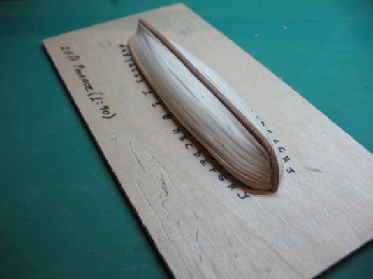
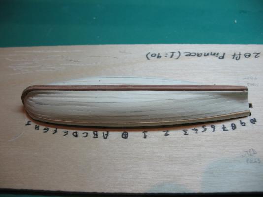
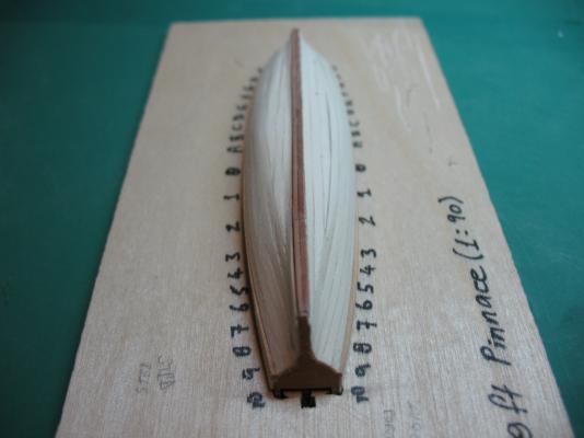
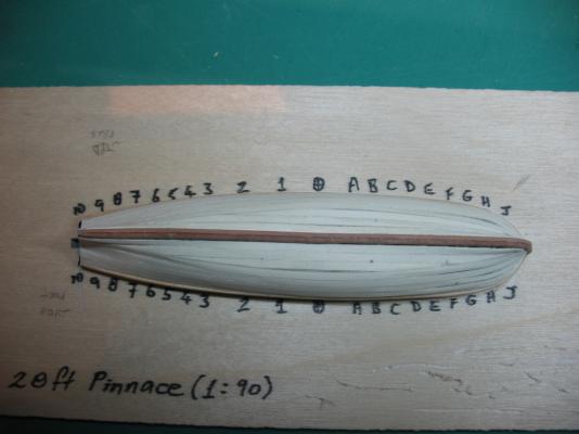
Thanks B.E. and Alan. In my last post I commented on the difference between the Dremel and the Marathon Micro Motor rotary tools. Here is a pic to show the relative size. Not only is the Dremel considerably larger, it is much bulkier to handle, heavier, and has no effective speed control (despite it being nominally variable speed). Ship's Boats continued: I finished the planking the Pinnace today, along with an initial (rough) sanding. As this hull will be painted, I could afford to take a few liberties with planking technique. So while it is not absolutely correct, it does provide a good foundation. I will be applying a little filler using a new (to me) product next, to achieve a nice smooth hull surface. I am inclined to do this prior to separating the hull from the build board. In the meantime, here are a few pics of the progress to date:


-
Thanks Augie and Keith (and also all of the "likes"). Keith - I totally agree with you on micro motor vs Dremel. I might take a picture of them side by side to show the difference in hand piece size. The Dremel is huge by comparison. To answer your question, I will probably lay the garboard plank as the second to last on each side with this boat. On the Cutters, it will be first (for obvious reasons).
-
Nice job thinking ahead again there Bob, in tying off the fore lower sheets. This is developing into a really superb model.
-
I'll agree with Bob, who agreed with Chris...... subtle is better in this case. It looks fabulous Remco.
-
Thanks very much indeed B.E. and Bob. B.E. - it's actually a whopping 95mm (rounded) long (not 68) The cutters will be shorter at 85mm, but wider in the beam. The challenge with them will be the clinker planking.