


gjdale
-
Posts
4,871 -
Joined
-
Last visited
Content Type
Profiles
Forums
Gallery
Events
Posts posted by gjdale
-
-
That’s very interesting Egilman - thanks for that little bit of history/knowledge. 😊
- Canute, Keith Black, mtaylor and 4 others
-
 7
7
-
-
I just stumbled across this build. Great work so far on a very interesting subject. I’ll be following along from here.
-
Glenn,
Thanks for taking the time to share your learnings and contribute to discussion on this subject. As you say, there are many ways to tackle this task and yours is clearly a valid way. I personally use a jig very similar to the one shown and described by Kurt, and I have also used a method similar to that described by Mark Taylor. All of them are valid. All of them are safe as long as you follow appropriate precautions for your chosen method.
Please don’t regret your original post based on a few ill-considered comments. The rest of us appreciate your contribution.
-
Thanks guys,
3 hours ago, BobG said:Regarding the locator pin: Is it necessary to melt the pin? Wouldn't the glue be enough to hold it strongly?
Good question Bob. I was just following Paul Koo’s advice and he hasn’t let me down yet. I think that melting the pin is the primary holding method and the glue is just extra backup.
-
I’m very interested to see this one come together Kevin, so I’m pulling up a front row seat right next to Sjors and the popcorn. We just need Mark Taylor to arrive now to open the bar!
- BobG, Kevin and Old Collingwood
-
3
-
Body Work (continued)
The next step was to assemble the hood. At this stage I also added some chrome trim using Monokote Chrome trim. Of the four Hood latches, only the two rear latches are functional, with the forward latches being dummies. So these dummy latches were also attached.
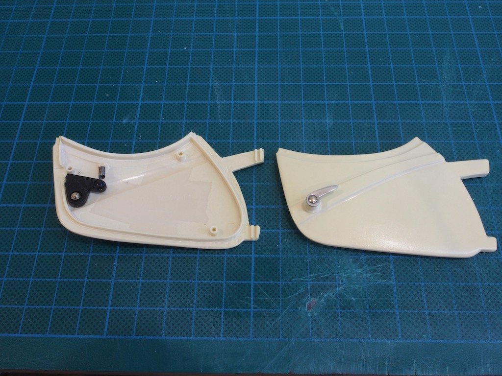
Next up was the doors. The doors are supposed to have working latches, but the design is poor, so a modified approach was taken, following Paul Koo’s recommendations. In the photo below you can see the door handle applied on the outside of the door, with the modified latch and spring mechanism attached on the inside of the door. In theory this should still make the door handle spring-loaded, but in practice this still doesn’t work terribly well.
The door liners are then added and the next problems dealt with. The kit instructions call for these to be attached with small cheese-head screws. First of all, the holes in the door liners do not align with the screw post in the door, so these have to be adjusted. Secondly, if the cheese head screws are used, these will subsequently protrude as lumps under the leather lining. Thirdly, the screws are too long and if not shortened, will go right through the door. The solution to the second and third problems was to replace these screws with countersink screws that were cut down to an appropriate length. Here are the door liners in place.

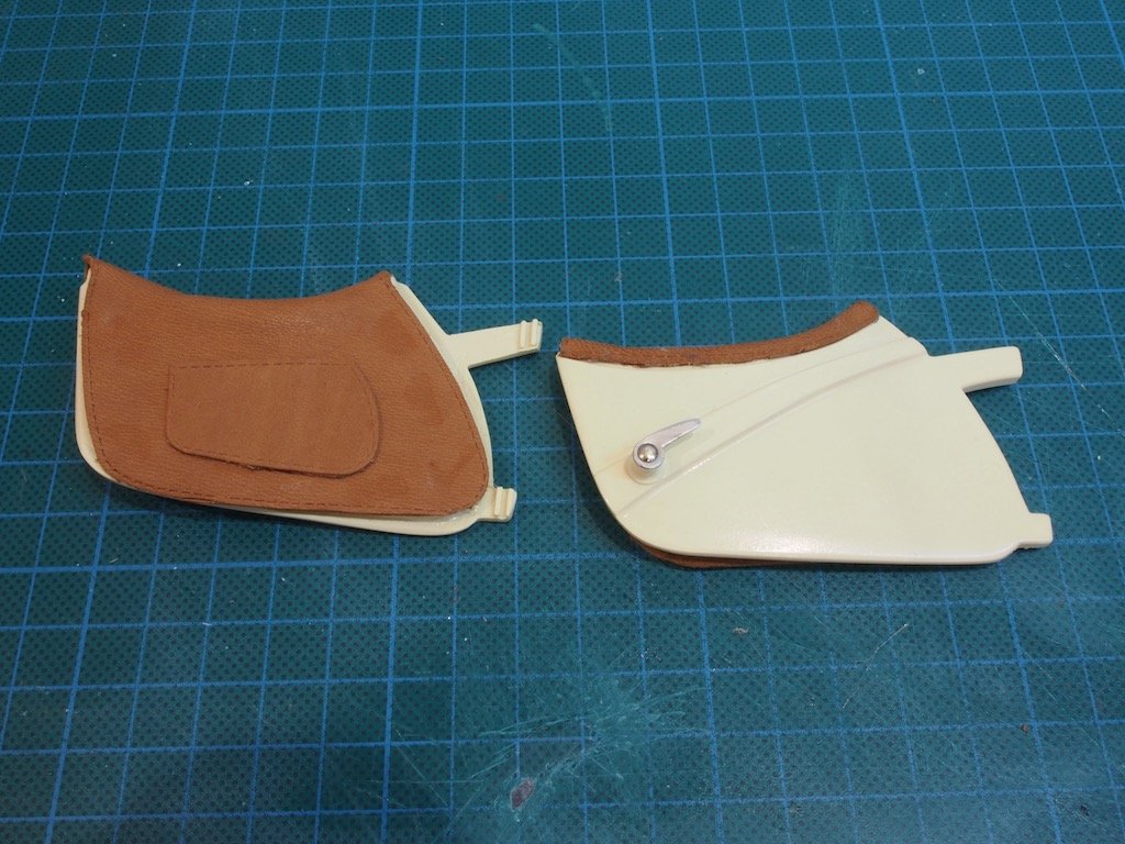
The final stage for the doors was to apply the leather upholstery. This turned out to be a lot easier than I had anticipated. Following Paul Koo’s advice, all upholstery was glued using Automotive Goop. As a nice additional touch, a separate piece of leather is provided for the map pockets on the doors.
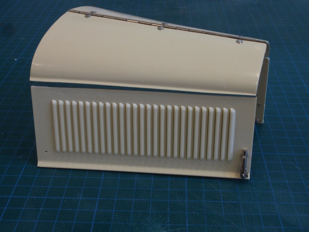
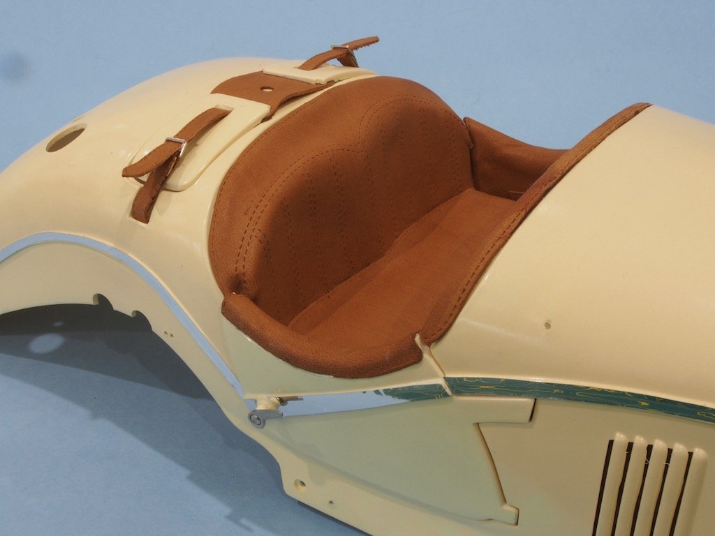
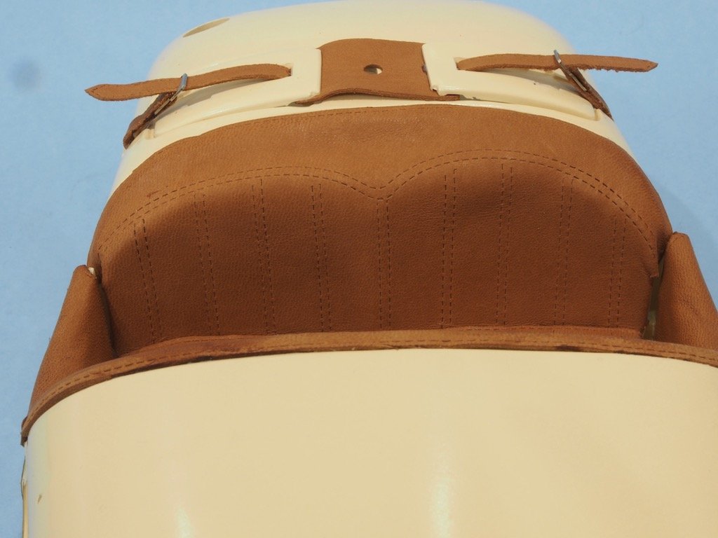
The main body then had its upholstery applied. This included seat backs, seat bottoms, dashboard cover, foot-well side panels, and luggage box straps. Monolote chrome trim was also applied, although the photos do not do this justice due to the way the light catches this in the photos.
Here is an overview of the main body upholstery.
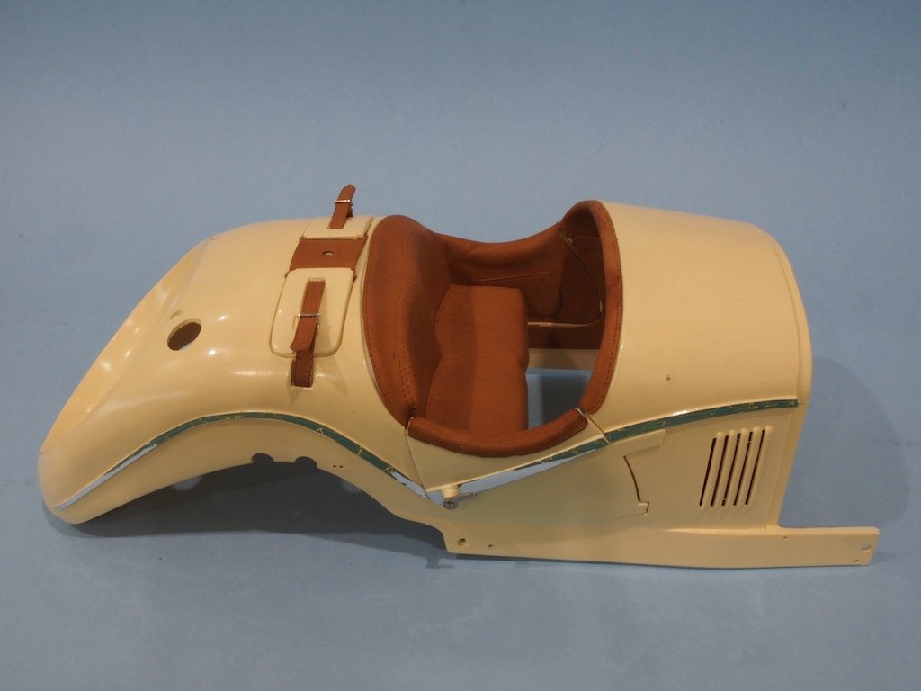
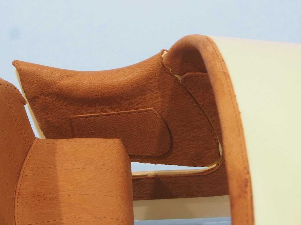
And here are a few extra shots with some close ups showing the stitching detail and the door pockets:
The carpet was also applied to the floorboards, though I didn’t take a photo of this.
Next up will be the addition of extra fittings prior to installation of the body parts. Stay tuned….
-
Body Work
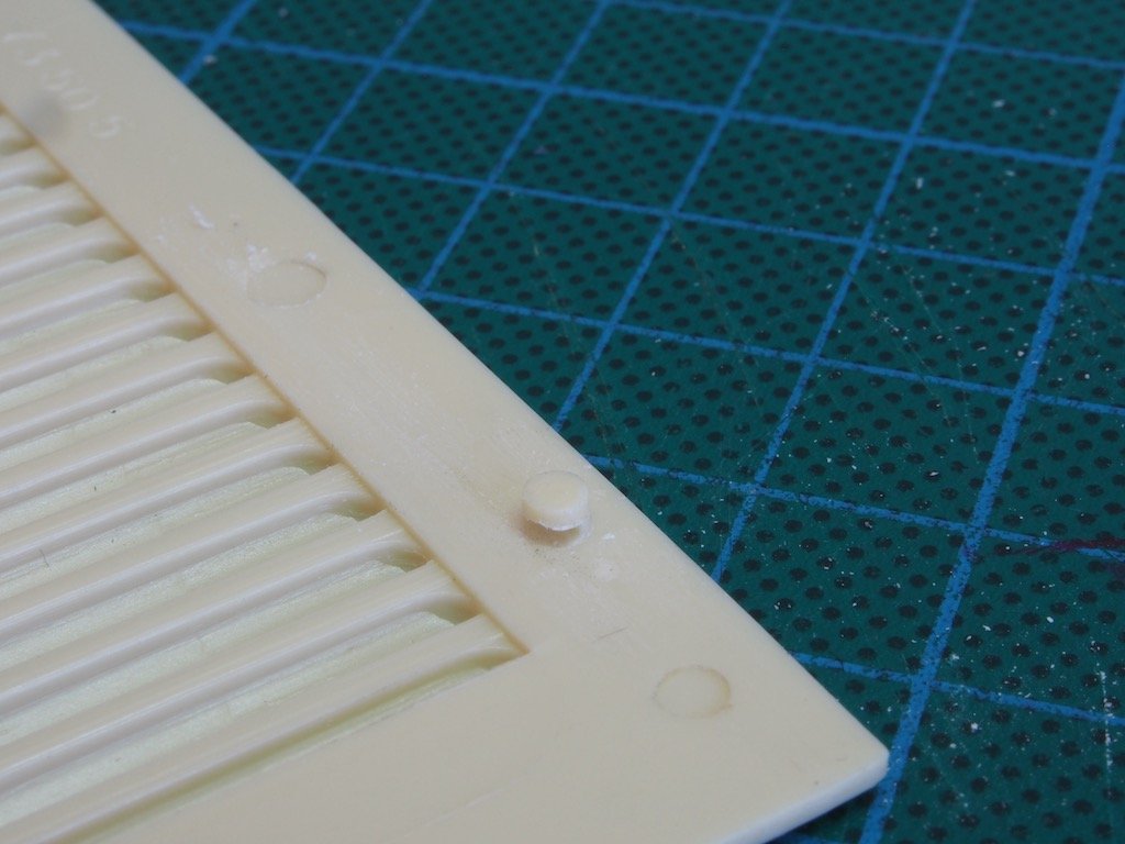
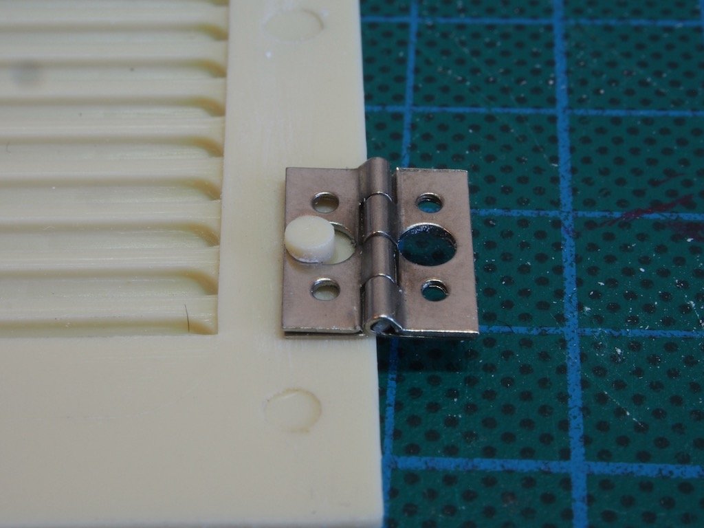
It's been over a month since my last update, but that doesn't mean that I haven't been working on this model. On the contrary, there is a lot of preparatory work required before installing the body works. This begins with the Hood panels. There are small hinges that attach the side and top Hood panels. The kit parts have locating lugs to position the hinges. A great idea, once again poorly executed. The problem is that these are in the wrong place. The photo below shows a hinge in place on a side panel and illustrates well the problem – the hinge pin is way too low and needs to be moved up.
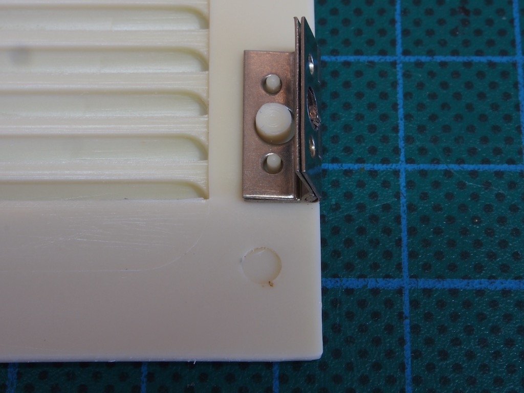
In the next photo you can see where I have removed the small locator pins and then filed a notch into the main locator to allow the hinge to be moved up.
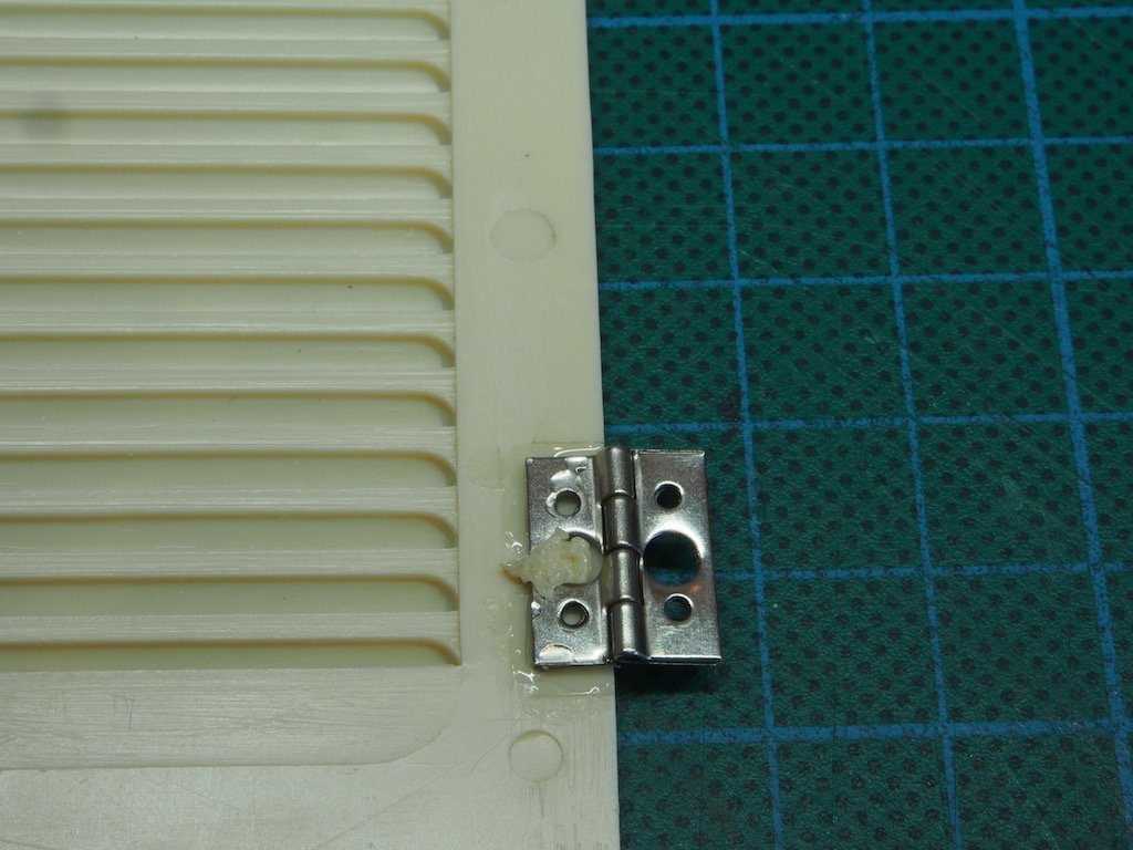
The result is shown in the next photo – a properly located hinge.
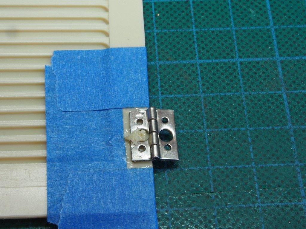
The hinge is then fixed in place by first melting the locator pin and then applying glue around the hinge. The masking tape is simply to contain the glue.
And the final result:
This process was then repeated with the remaining panel hinges (four in total). Once attached to the side panels, the locating pins on the top panels had to be similarly adjusted both for hinge height and also for fore and aft alignment to ensure the top and side panels were perfectly aligned. A photo of the completed hood is further down in this update.
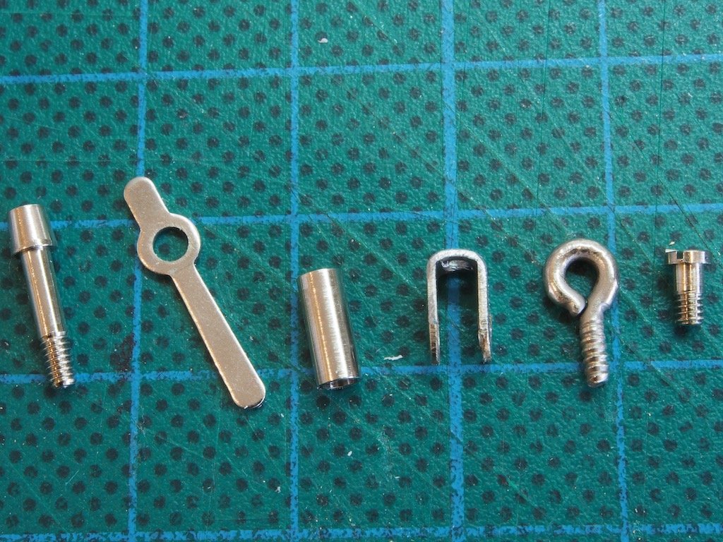
The next job was to make up the four Hood latches. Here are the components for one of these:
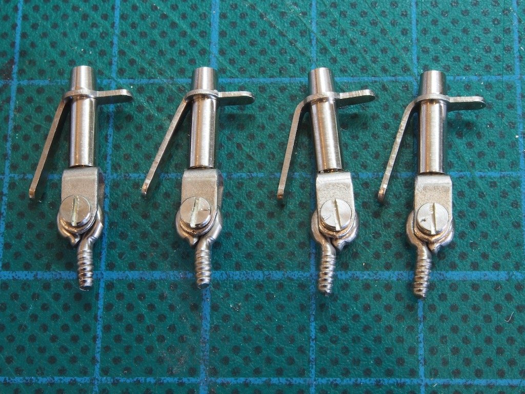
And the completed Hood latches:
Next up was painting the main body parts. This stage seemed to take forever as I experimented with a number of finishes and made a few mistakes along the way. First up, because of the overall size of this model, I took the advice of Paul Budzik (who is a member here and has posted many useful and informative videos on YouTube). That advice was that a regular airbrush was not a good idea for this size of model. I won’t go into the reasons why – you can watch Paul’s videos for that. Instead I had previously purchased a mini HVLP spray gun, again based on Paul’s advice. The spray gun I used is the Iwata LPH-80 with a 0.8mm needle. While at first glance, this spray gun looks to be more complex than an airbrush, it is actually quite easy to set up and use. The catch is that it needs an air volume that is beyond what pretty much all airbrush compressors are capable of, so I had to hook it up to my large (and very noisy) compressor in the garage. The beauty of this gun is that it needs a constant air pressure at the gun (you need a gun gauge for this) of 13psi. Once you have that set, it just a case of adjusting the material (ie paint) flow until you get what you want, and then adjusting the fan pattern similarly. Of course, a change in one means you need to tweak the air pressure to maintain that 13psi, but that is actually really easy to do.
My next lesson was about filtering the paint. I had assumed that using a quality primer and paint such as Vallejo would mean that I could just go ahead and spray, with perhaps some thinning, depending on the actual paint. I found that despite good stirring/mixing and thinning, I was still getting clogs and spitting, even with this larger needle. That’s when I had my major light bulb moment (or as I like to say, my Homer Simpson moment – oh, Duh!!!) and decided to filter the paint first. I bought some paint filters from an automotive shop and stripped the actual filter material from them. I then placed this over the mouth of the paint bottle, trapping it in place with the dispenser cap. And just like magic, all my painting problems disappeared……well, almost.
Having at last achieved a nice primer coat and colour coat, I had to decide on clear coats. I wanted to stay away from some of the nastier types, so tried several acrylics – none of them particularly satisfactory. I had read online and seen YouTube videos of plastic modellers espousing the virtues of Pledge/Future floor finish as a great clear coat. I was sceptical at first but eventually decided to give this a go. Of course, this product cannot be bought in Australia, so back to online shopping and managed to track some down via eBay. A couple of weeks later that arrived, and I did some trials, finding that the more coats of this that were applied, the shinier the surface became. I found that four coats of this gave quite a nice finish. It sprays beautifully and self levels very well too.
My next lesson was that acrylic paints are impossible to polish as one might with enamel paints. The slightest abrasive surface, even with micromesh polishing pads, will quickly strip the clear coat and the colour coats. The best I could manage was to use Novus polishing liquids with a soft cloth. Even then, I could only use the No.2 Fine scratch remover and the No.1 Finishing polish – even the No.3 Coarse scratch remover removed all the paint.
So after several weeks of trial and error, and re-dos, and more errors, and more re-dos, I finally had the body parts to a useable state. Here they are, ready to go.
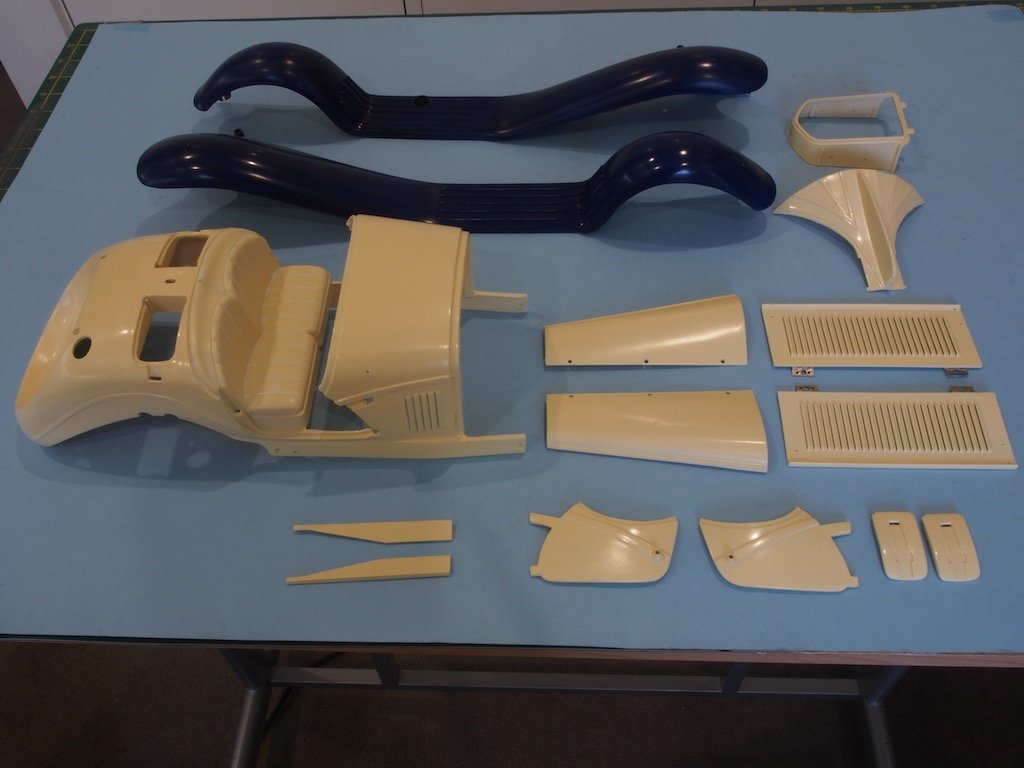
Continued next post.....
-
Welcome home Adam, we left the light on for you.
- mtaylor, BobG, Ryland Craze and 2 others
-
5
-
-
Curse you Mark - I’ve just ordered a copy! 😉
-
-
Your rebuild/repair efforts are really paying off Kevin. Don’t know what to advise on the colour scheme. I kinda like the original but you’re the Captain as they say.
- Kevin and Old Collingwood
-
2
-
If you didn’t already have a saw, I’d say go for the saw, but as you have a Proxxon one that can do the same function (albeit not as nicely), then perhaps the disc sander would be higher priority as it fills a gap in your arsenal? To be honest, I’d say the disc sander is probably the most used of the power tools for me.
-
I’ve been watching a series of YouTube tutorials on machining with lathe and mill by Blondiehacks, recommended by someone else here (Greg Herbert (DVM) if I recall correctly). As well as being excellent tutorials, she has a great mantra around safety. She often says something along the lines of “always remember, these machines are actively trying to murder you - don’t let them!” Good advice me thinks!
-
-
-
There is quite a mix of metal and plastic, but very little glue is used. Most fastening is done with bolts/screws. The challenge is getting things to align properly, ‘cause they rarely do straight up. Also, pre-drilled holes are invariably too small and need to be opened up to avoid cracking plastic parts. Then there is the inevitable modification required to make things actually fit - eg melting bolt heads down into the plastic frame so that they don’t interfere with subsequent fitting.
Hope to have an update to the build this weekend - have been experimenting with paint of late.
- Canute, Ryland Craze, BobG and 5 others
-
8
-
It’s been worth the wait Mark - looking very nice.
- Edwardkenway, Jack12477, Canute and 4 others
-
7
-
-
Richard,
Check out Chuck’s offerings in the Syren Ship Model shop:
https://syrenshipmodelcompany.com/turned-brass-cannon.php
Also, Chris Watton is developing some for his Vanguard Models range, though I don’t think they are ready for sale/distribution just yet.
-
-
Well done Dave - that looks great. You can be proud of this build!
- LMDAVE, Louie da fly and BobG
-
3
-
I’m pulling up a chair too. I’ve had this kit in my stash for a few years now - one day.....
You’ve made a nice start Ray.

HMS Pegasus 1776 by Trussben - 1:48 - Swan-class sloop based on TFFM
in - Build logs for subjects built 1751 - 1800
Posted
Nice idea with the transparency overlay Ben. Looking good!