


gjdale
-
Posts
4,872 -
Joined
-
Last visited
Content Type
Profiles
Forums
Gallery
Events
Posts posted by gjdale
-
-
Looks like the repairs are going well Kevin - well done.
-
Fantastic outcome on the paint job Bob! Good luck with the clear coat. After doing some research myself, I’m going to do some trials using Liquitex high gloss acrylic varnish. It can be thinned with the Liquitex Airbrush medium. It can also be dulled down by adding some of their Matte varnish, so you can make your own recipe for how much gloss you want. I’m also going to put it through the mini spray gun rather than the airbrush. Not sure how it will go, but if it works the Liquitex is a heck of lot cheaper than the standard model paints/varnishes.
I’ll be very interested to see how your clear coat turns out. I’ll be cheering for you!
-
That looks to be a more than fair interpretation to me BE - well done!
-
If you haven't found them already Bob, there are some great little tutorials on airbrushing and airbrush equipment by Paul Budzik, who is also a member here at MSW. Occasionally he posts a link to one of his videos here, but they are easily found on YouTube. He covers a lot more modelling techniques than just Airbrushing, and his tutorials are really well done - his explanations are easy to follow and he knows what he is talking about (more than can be said for a lot of YouTube content out there!!!). Worth a look if you really want to understand airbrushing. I think he would probably say that for a hull the size of your Pen Duick, you really should be using a small spray gun, rather than an airbrush. Again, his videos do a great job of explaining why.
- BobG, Keith Black, lmagna and 5 others
-
 8
8
-
Yes I am Bob. Vallejo recommend using the gloss black primer for the Metal Colour range. I’ve had a few issues with the Vallejo primers generally in terms of finding the right “recipe” with thinner and/or flow improver, as well as air pressure to prevent the airbrush clogging. Reading on the internet, it seems I’m not the only one. A few people say they have no problems shooting it straight from the bottle, many more say they just can’t get it to spray properly at all. The gloss black primer seems to be more temperamental than the grey (which is my otherwise ‘go-to’ primer). I’m still experimenting....and have stripped and re-started on more than one occasion - including last night when I stripped the fuel tank back and started over.
- Ryland Craze, Canute, Keith Black and 5 others
-
8
-
Thanks for all the likes folks.
Bob, to answer your questions:
6 hours ago, BobG said:What paint are you using to get this realistic looking metal?
I’m using Vallejo Metal Colour paints, sprayed with my airbrush (Harder and Steenbeck Infinity with 0.4mm needle). I used Dull Aluminium for most of the engine and associated parts. I used Steel for the radiator and for the drive shaft and rear axle. And I use Gun Metal for hand painting the highlighted bolts where appropriate.
6 hours ago, BobG said:What kind of glue did you use for attaching the brass stiffeners to the soft rubber leaf springs?
I used thin CA for this. It forms a pretty much instant bond between brass and the rubber, so it needs to be done carefully. I applied a small amount in the mid section, then worked outwards a little at a time.
-
NIce to see you back at this one Kevin. I’m in!
-
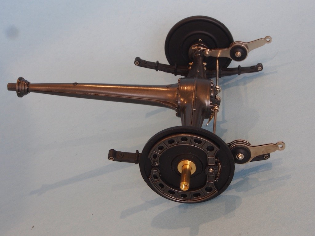
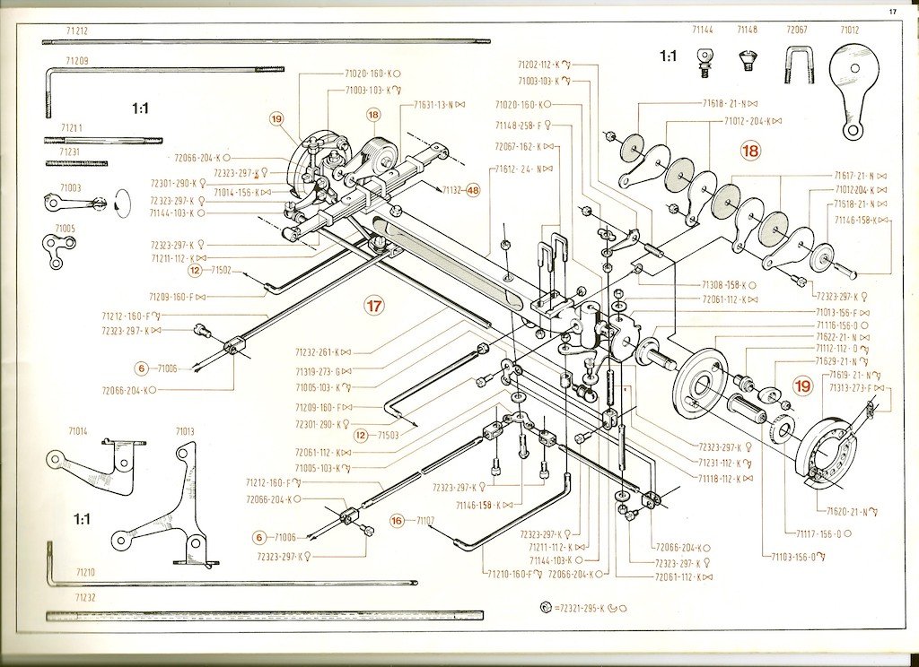
The Rear Axle
Once again, some test fitting, modification, disassembly and re-assembly are required. Another 88-page photo essay from Paul supplements the one-page Pocher diagram.
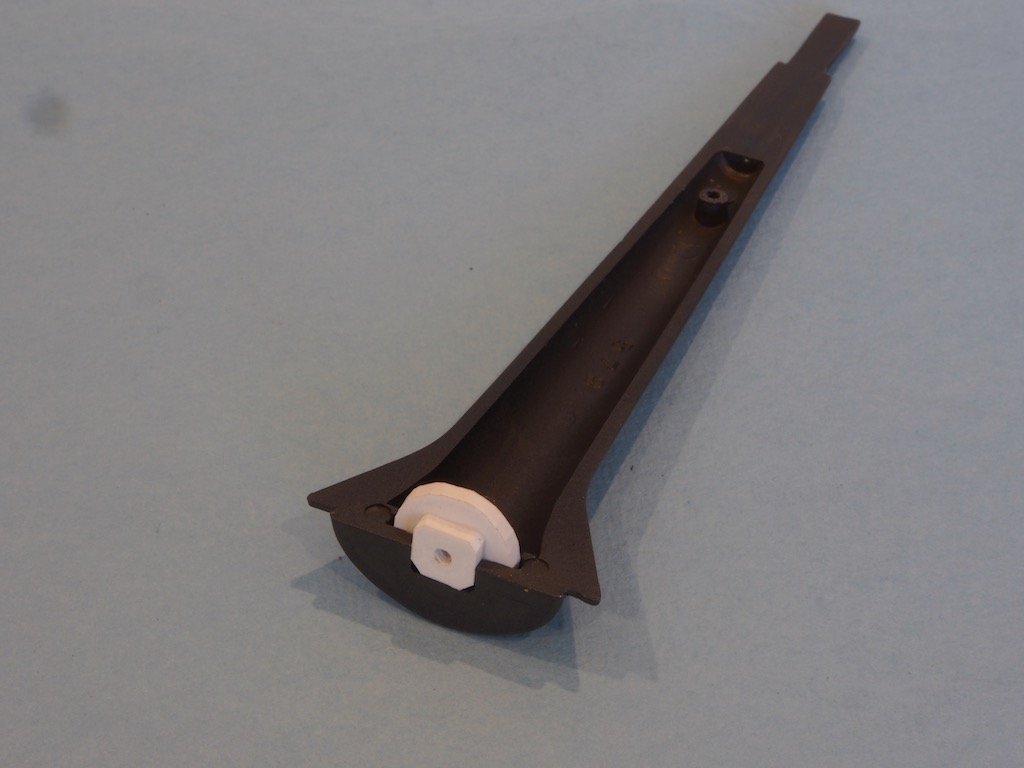
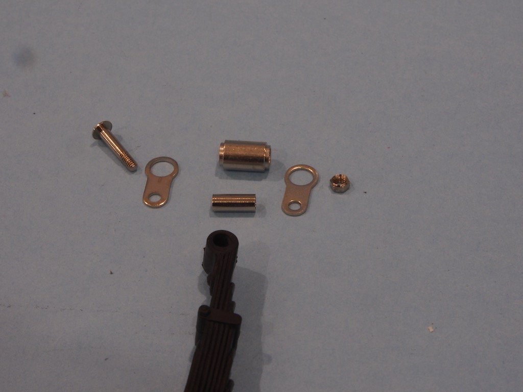
Assembly commences with the drive shaft. It comprises two main components, two rear spacers, and an internal part that receives a screw for attaching the rear axle to the drive shaft. As the internal part did not require painting, it was set aside while other parts were painted. Of course, when I went to commence assembly, it was nowhere to be found! Fortunately, it is not a complicated part and I was able to manufacture a scratch-built replacement from a couple of pieces of 2mm styrene sheet. The photo below shows the new part glued in place in one half of the drive shaft.
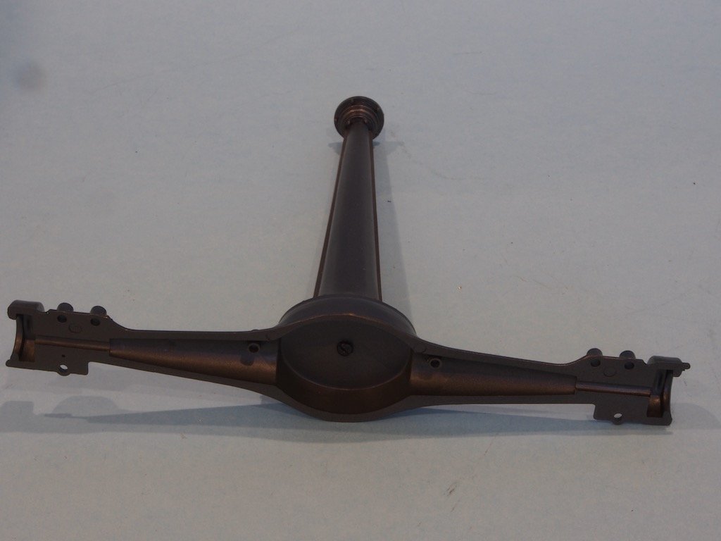
The other half of the drive shaft was then put in place (held in place by two screws) and the first half of the rear axle housing was screwed in place using the new part to receive the screw.
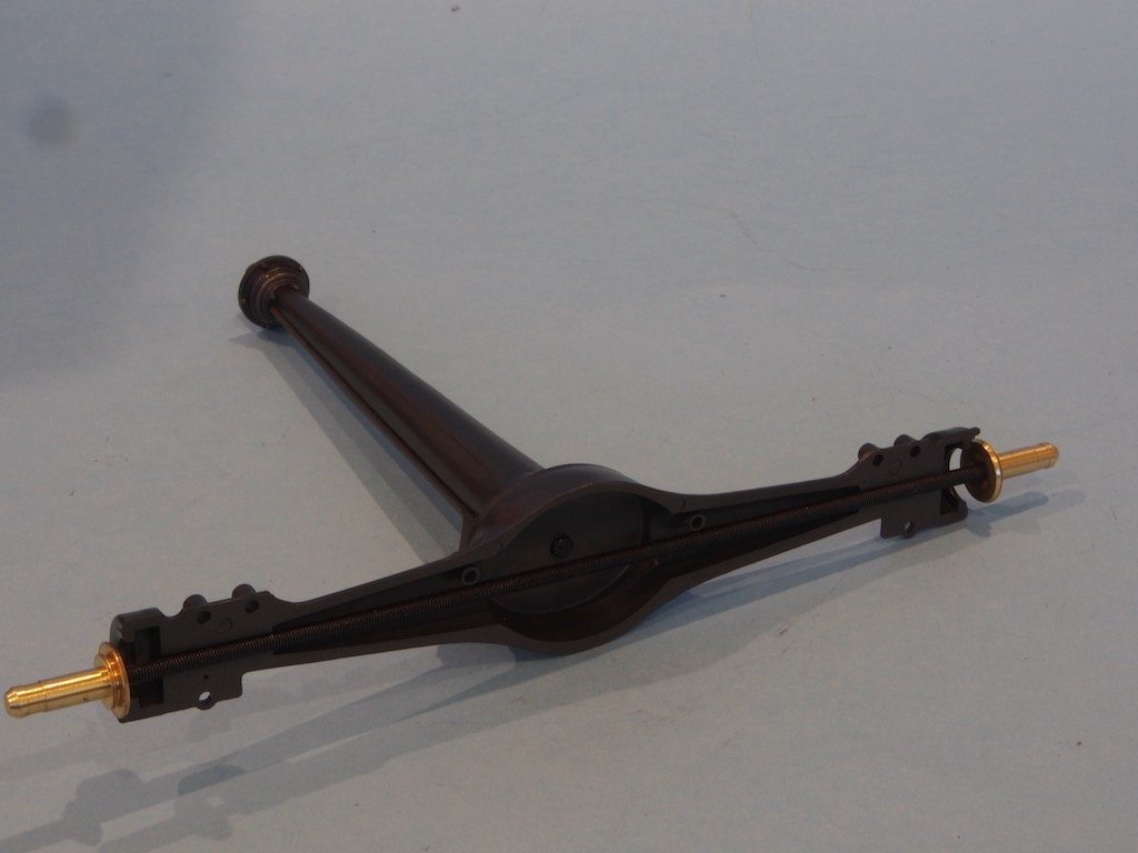
The actual rear axle is then put in place with its two wheel hubs.
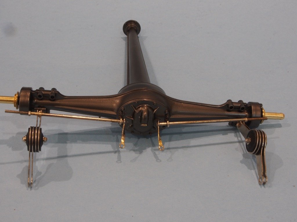
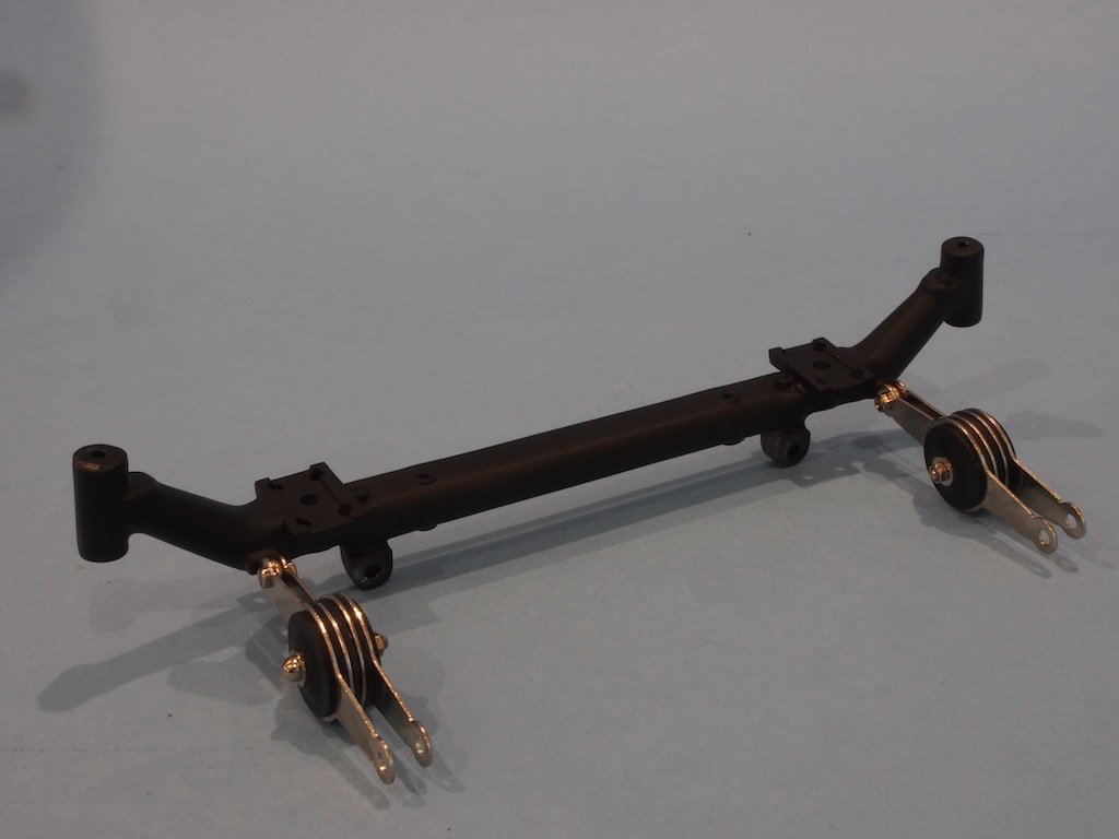
The front half of the axle housing was then attached and the rear dampers assembled and added in much the same way as for the front axle. The rear brake linkages were also added at this stage.
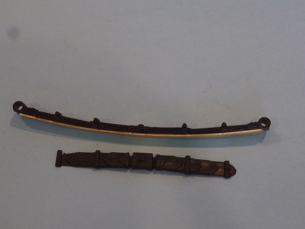
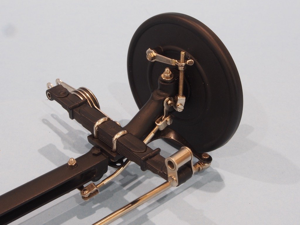
At this point the rear leaf springs are required. All of the leaf springs are made of a soft rubber compound rather than hard plastic. Paul notes that while these are okay for the front axle, they are too soft for the longer rear leaf springs and suggests modifying them. Although Model Motorcars does offer some very nice after-market photo-etch leaf spring assemblies, at USD $130 per set plus the exorbitant postage rates from US to Australia, plus the eight week plus current postal delay, this was not really an option. Paul’s second option is to modify the rear leaf springs by cutting them in half length-wise and inserting a piece of 1/32” x 1/4” brass strip to act as a stiffener. I chose to go with this option. The hardest part was cutting the original leaf springs in half. I did this using by Byrnes table saw and very dodgy holding jig.
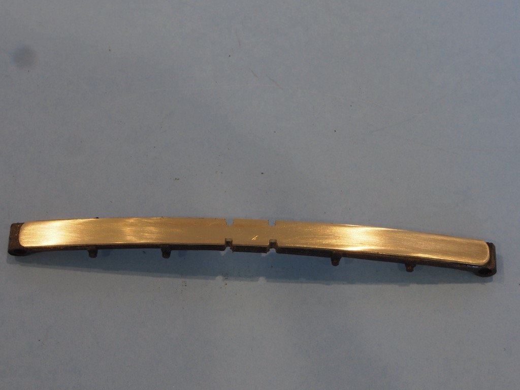
Here is the leaf spring cut in half and the pre-bent brass inserted.
Matching notches were cut in the brass using a cut-off wheel in my Dremel-type tool.
Then the top half was reattached and the entire assembly re-painted.
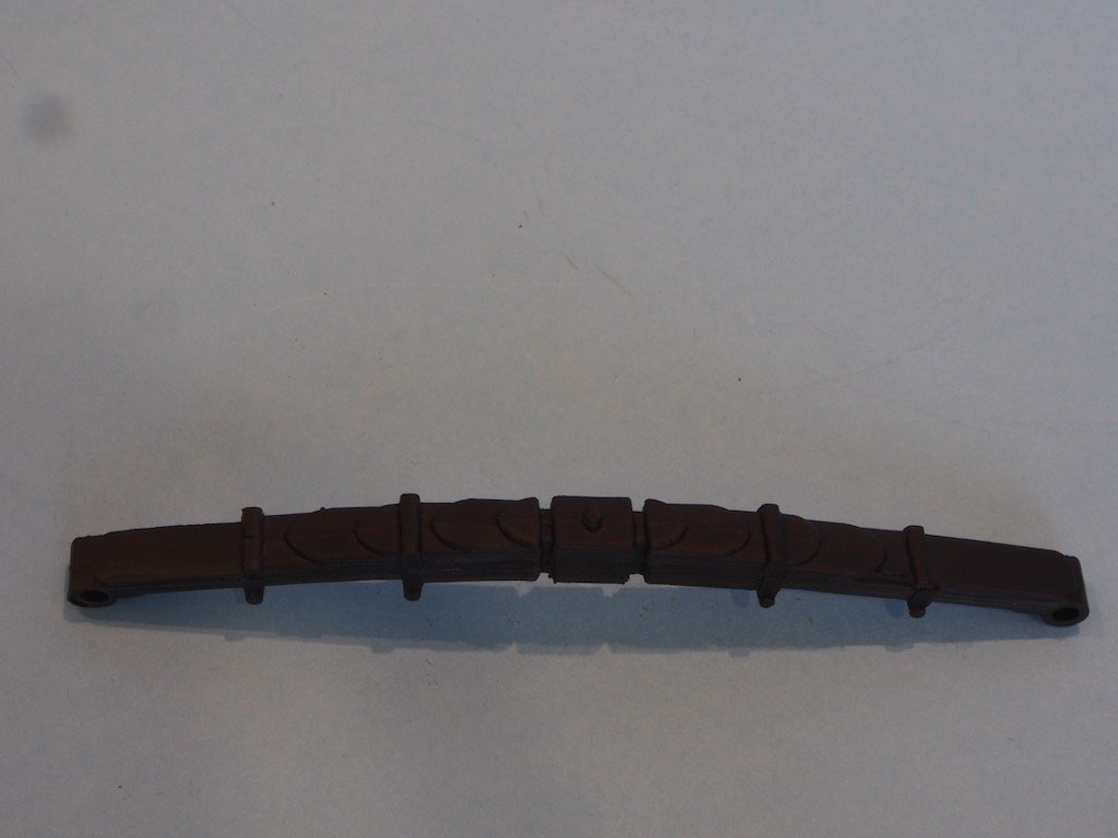
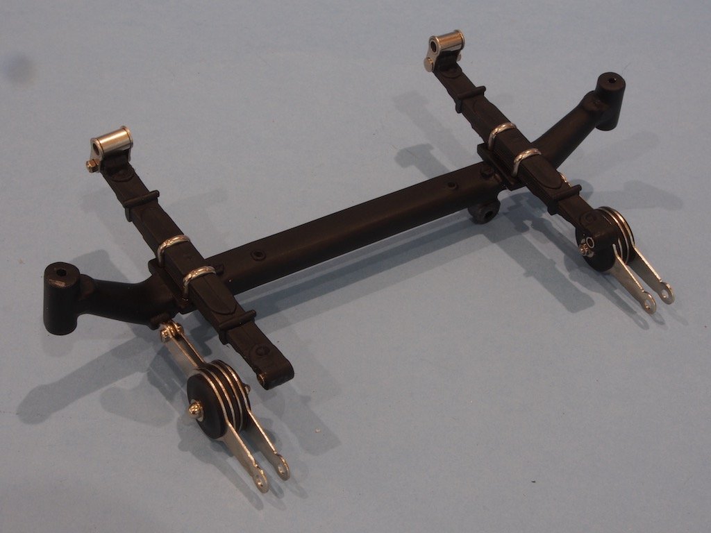
The completed leaf spring was then attached to the rear axle. The wheel plates had the brake cams installed and these two were then attached to the rear axle.
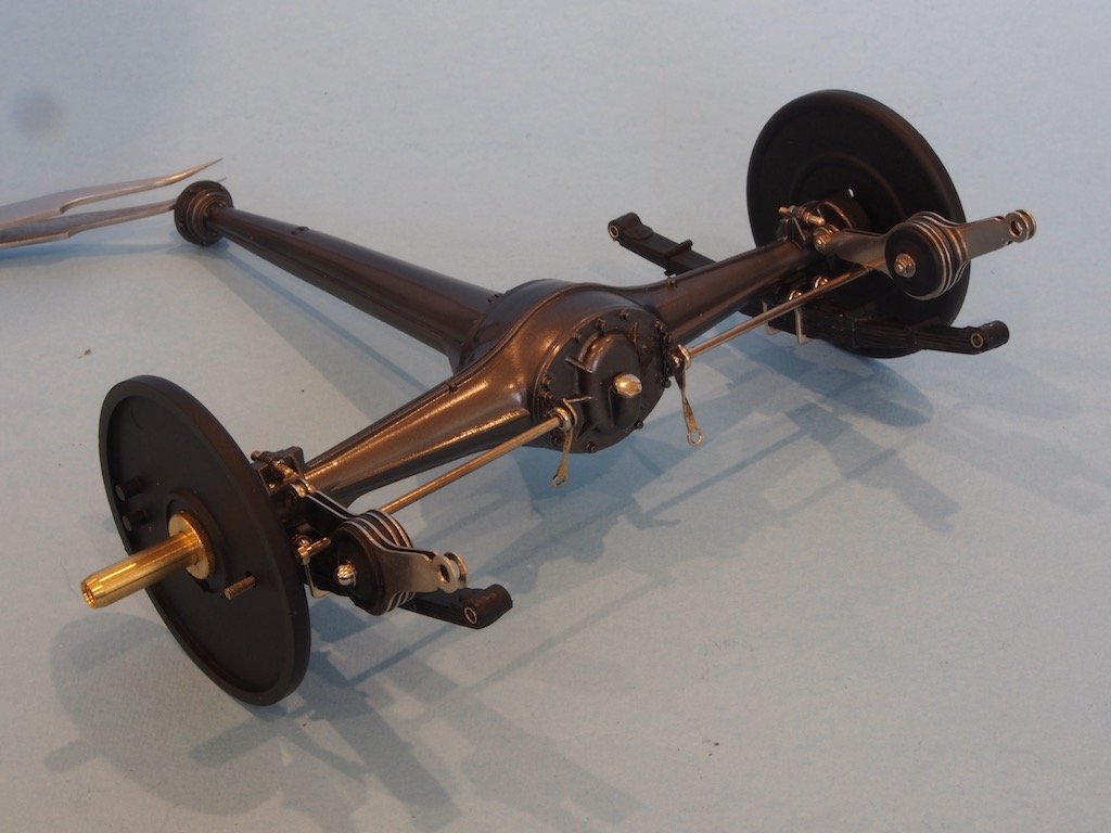
Brake shoes and springs were then inserted as per the front wheels.
The entire assembly was then test fitted with only one of the two rear spacers fitted. The gap between this and the transmission was then measured and the second spacer sanded down to this thickness prior to final fitting.
The brake linkages were then fitted between the brake connecting rods and the transmission levers.
Another view.
Final attachment of the rear axle requires the dampers to be attached to the chassis. However, a couple of extra parts need to be in place prior this. These parts are now in the paint shop and will be fitted during the next phase of construction.
-
-
-
That’s looking great Dave. If you are going to maintain an option for RC, then you might want to consider Spar Marine Varnish as it has UV protection built in to protect the finish from yellowing over time.
- Louie da fly, Nirvana, LMDAVE and 1 other
-
4
-
Ingenious modification BE, but that shouldn’t really surprise us now should it? 👏👏👏
- BobG, Blue Ensign and Beef Wellington
-
3
-
Bob,
I’ve sent you a PM with Paul Koo’s direct email address. I suggest contacting him if you want to know a fair price for any of these Pocher kits.
- mtaylor, Landlubber Mike, BobG and 5 others
-
8
-
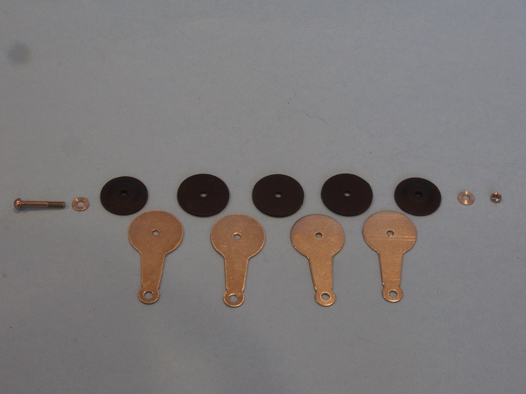
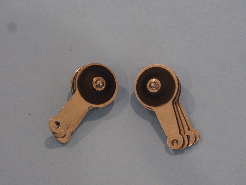
Next up are the front wheel plates. These get fitted with the rotating axle hubs and a strange looking metal piece that I have no idea of the name. I forgot to take a pre-assembly picture, but here is what these look like assembled together:
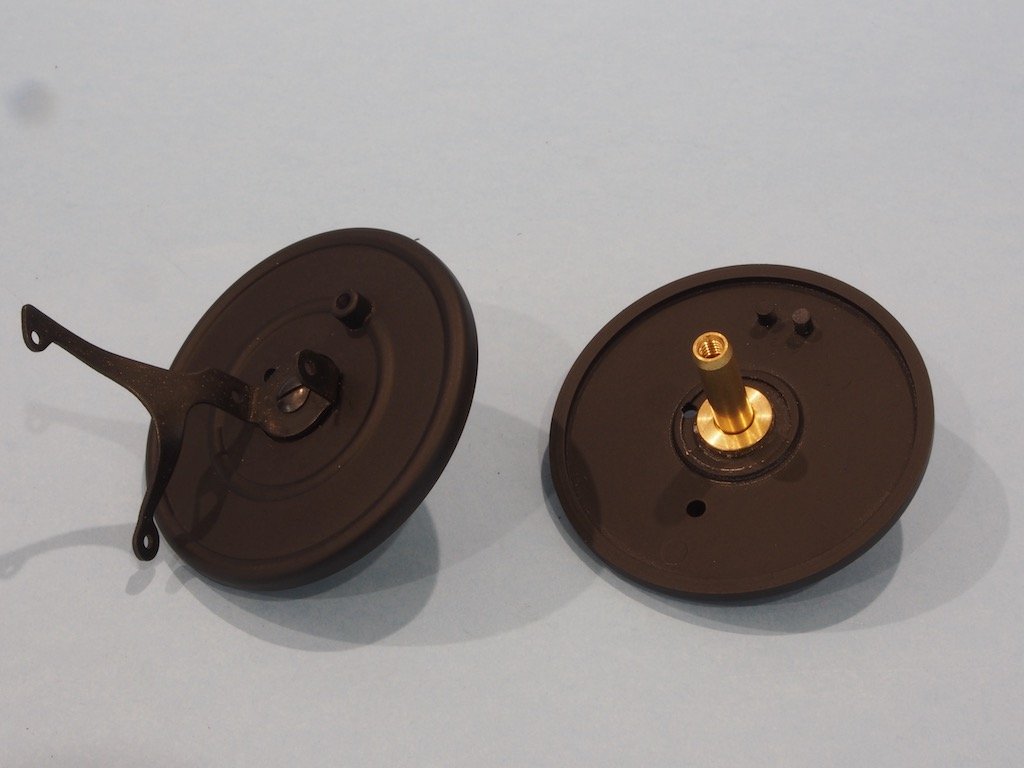
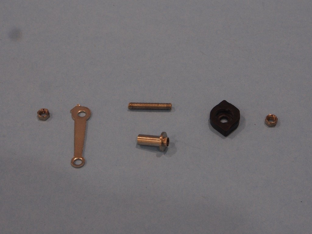
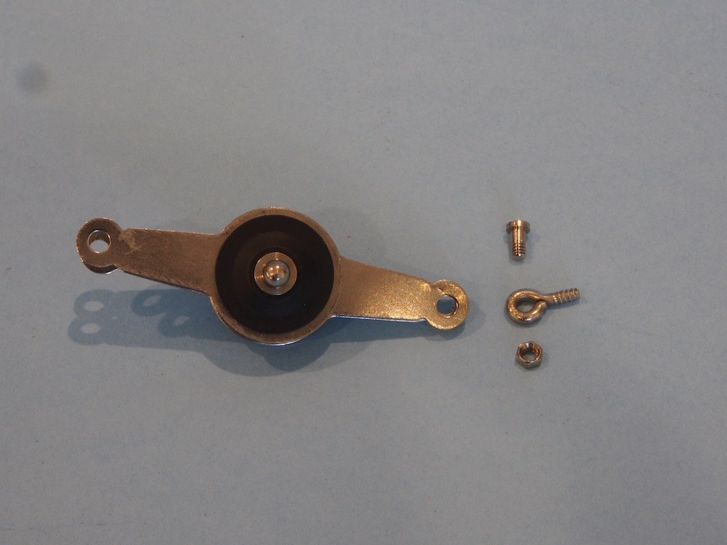
The front brake cams then need to be fitted to the wheel plates. Here are the components and pre and post assembly:
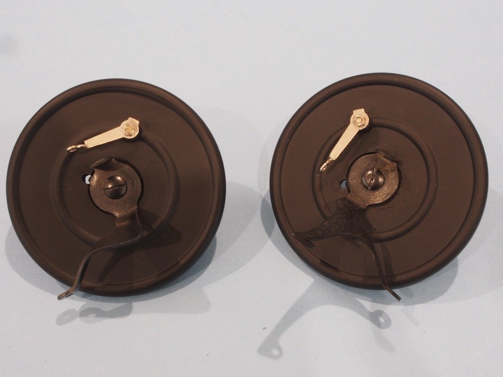
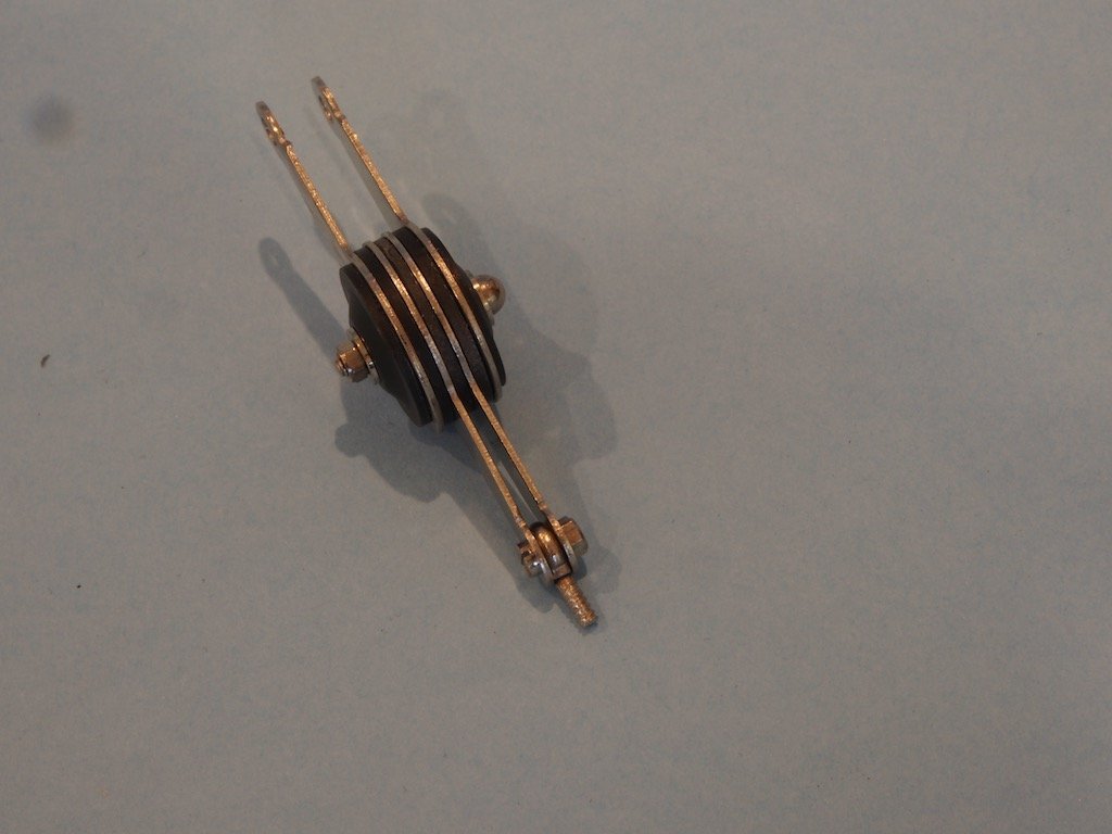
On the other side of the wheel plates, the front brakes themselves are fitted:
If you look closely you will see the spring joining the two brake shoes running over the top of the brake cam. The brakes are supposed to be fully functioning, but the springs are a little too strong and the cam a little too weak. It is supposedly possible to fix this issue, but it is not easy and I’m not going there!
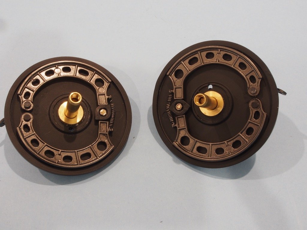
The wheel plates are then fitted to the front axle:
And here is what the front axle looks like so far:
The tie rods, brake linkages and front axle braces are fitted next, with some judicial additional bending of the front axle braces and some extra threading added to them as well:
The front axle brake linkages are then added back to the transmission brake levers:
And finally, the steering control rod is added back to the control arm on the steering gear box. Again, this needed to have some judicial bending imparted and in this case was inserted from the opposite direction at both ends to that shown in the Pocher manual in order to provide a better fit:
The rear axle assembly is next...
- druxey, Canute, Old Collingwood and 10 others
-
13
-
Some progress was made last weekend, but I didn't get to update the log until now...
The Front Axle
The approach to the front axle is the same as for previous sections – ie test fit and adjust where necessary the plastic parts, then disassemble, paint and re-assemble. This is a quite complex assembly. The Pocher instructions are nothing more than an exploded parts view – with no information about the order of assembly.
A second page deals with the leaf springs, both front and rear, but these need to be addressed in conjunction with the front and rear axles respectively.
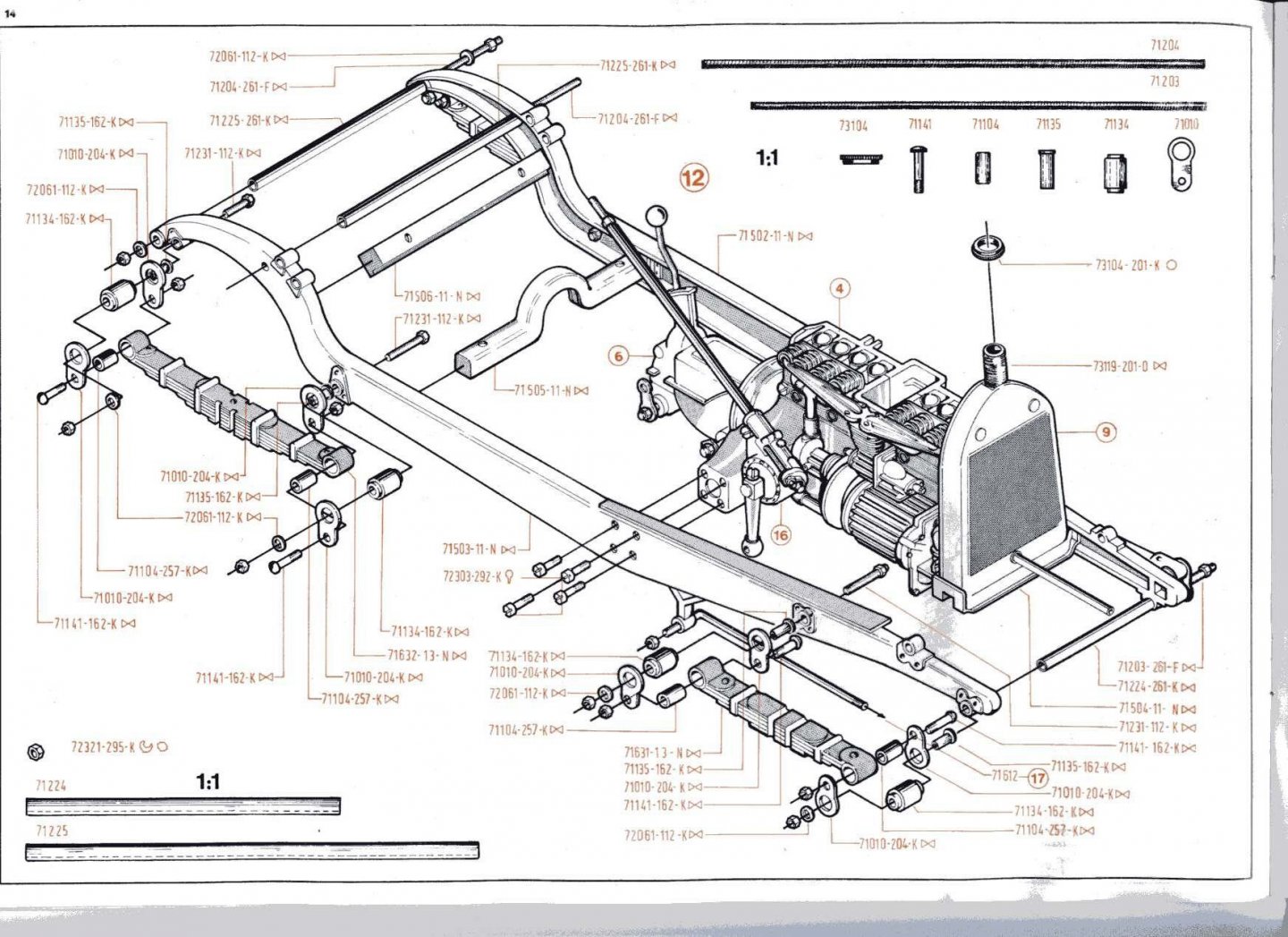
In contrast, Paul’s photo essay on the front axle is 96 pages long, with detailed explanations for both parts fit and sequence of assembly, as well as offering alternative methods for some parts to make the fit better and/or easier.
Assembly commences with the front dampers. Here are the initial components (there are two lots of these of course):
And assembled:
They then need to be affixed to the front axle:
The front leaf springs are next. Part of the leaf spring shackles were fitted to the main frame in the previous step. Here are the components for one of the rear shackles:
And the front leaf springs attached to the front axle:
Continued next post...
-
-
That’s looking nice and smooth Chris - should give you a great foundation for that second layer.
-
Welcome to the forum Rick. Please do start a build log once your kit arrives - this one is on my “bucket list”.
- mtaylor and thegrindre
-
2
-
Looking good Spider. I’m only just catching up with your progress. I used the little green tiles on my Victory and then painted them over with copper paint and then lightly sanded the copper paint to allow some of the green to show through, then sealed all with a clear finish. I think it came out okay. You are certainly taking it to the next level by applying copper tape over the top of the tiles.
-
Welcome to the forum from the Nation’s capital Jii. You’ll find there are quite a number of us Aussies here. Regarding first kits, although I’ve not built one, there are some nice offerings from Vanguard models available that are specifically designed with beginners in mind. There are also a couple of reviews of these kits here on the forum, and a few build logs underway. Although UK based, so postage will take a while in the current COVID environment, they could be worth waiting for. I don’t think you’ll find better sets of instructions anywhere.
- Louie da fly, mtaylor and JeffT
-
3
-
19 hours ago, Chuck said:
Its literally the same half dozen or dozen cranks that do this with every change we make.
Reminds of an Admiral once quoted as saying, “I’ve been in this outfit for 40 years. I’ve seen a lot of changes in that time. And I’ve opposed every single one of them!”
Keep up the great work Mods/Admins - I’m sure any minor glitches with the changes will be overcome (or forgotten) in time.
-
I view cleaning the airbrush much the same way as sharpening a chisel - keep the tool clean/sharp and it will serve you better. Once you get used to stripping down, cleaning and reassembling the airbrush you’ll find it’s not that big a deal and you’ll become very proficient at it - much the same as gaining proficiency (and speed) at sharpening a chisel. If you get lazy about either task, the tool will not perform at it’s best and you’ll end up taking longer over the main task and likely with more re-dos.
-
-
He has an ebay store:
https://www.ebay.com/str/pocherphilesforum
But if you are after a kit, you’re probably better off contacting him direct via email as he doesn’t necessarily put these up on the web. He can usually source particular kits for you as well. If you’re interested I can PM you his email address.
- Keith Black, mtaylor, Canute and 5 others
-
8

Alfa Romeo Spider Gran Touring by gjdale - FINISHED - Pocher - Scale 1:8
in Non-ship/categorised builds
Posted
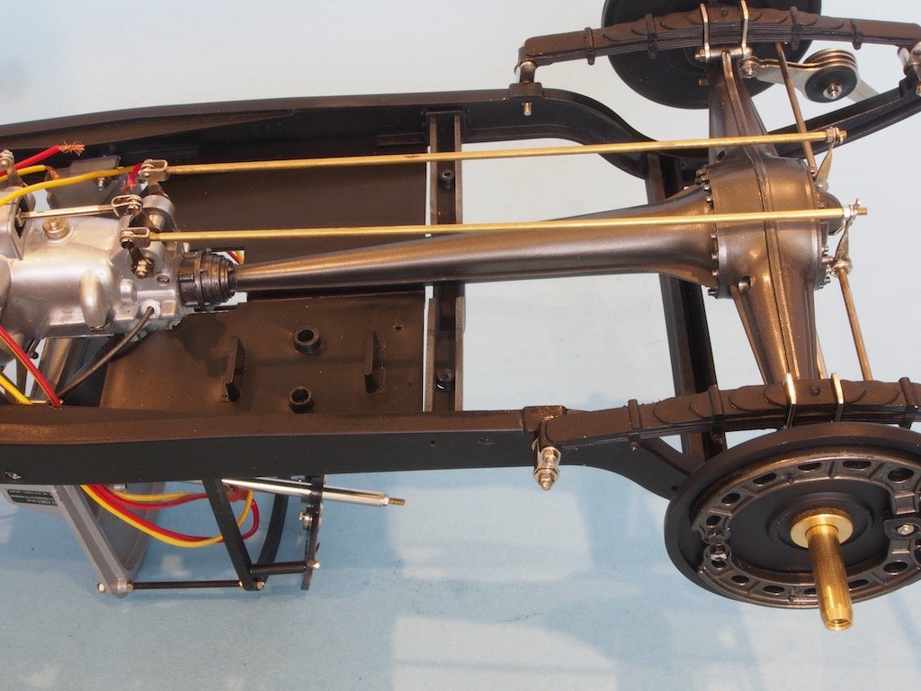
The Rear Axle (continued)
The rear axle mounts to the frame via two bolts through the rear floorboard, which first had to be adjusted in shape to enable it to sit horizontally once fitted. The rear bolt is used to also mount the rear dampers, however this part is incorrect to allow proper fitting of the dampers. Apparently in some variations of this kit a correct part was included but for the majority of the kit variations Pocher continued to supply the wrong part. Two options are available to correct this. One option is to replace the incorrect part with a custom machined part. A simpler, though still incorrect option is to mount the damper to the axle using the inner two damper plates and then mount the damper to the chassis using the outer two plates. While this is technically incorrect, it still looks okay, so this is the option I chose. The two luggage boxes are also mounted on top of the rear floorboard, with the left-hand luggage box being drilled through for the wiring to the battery box.
This completes the Rear Axle assembly.
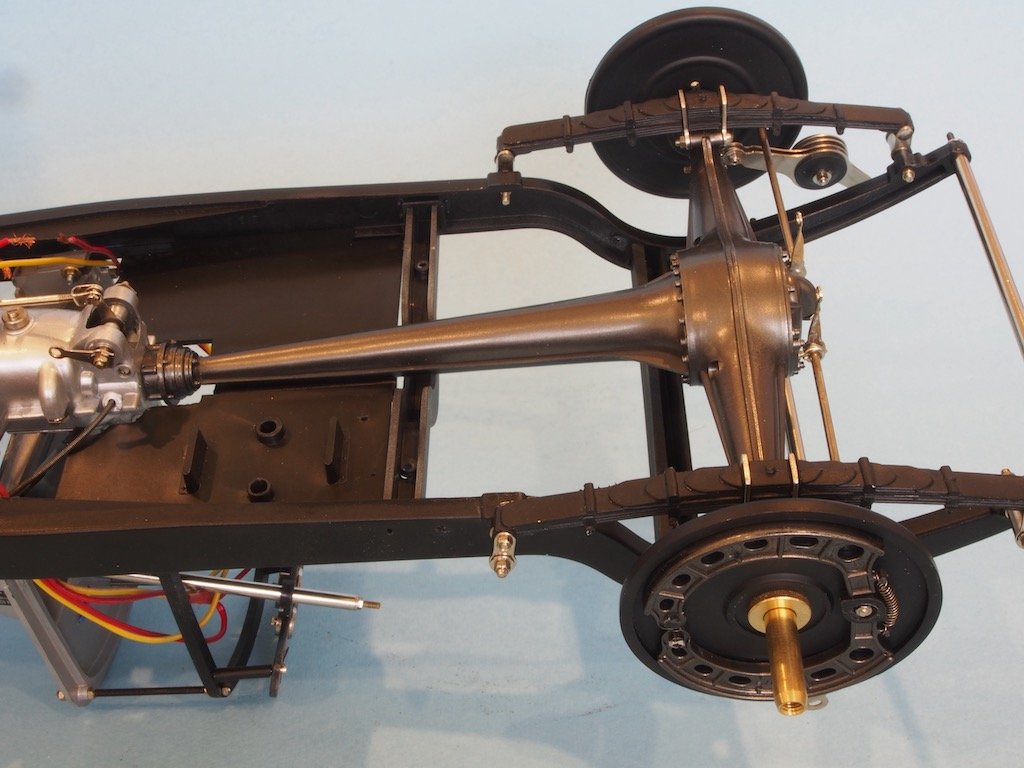
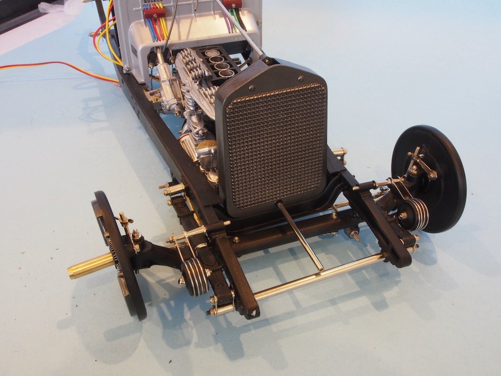
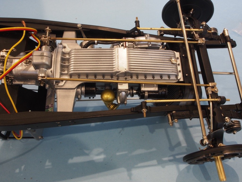
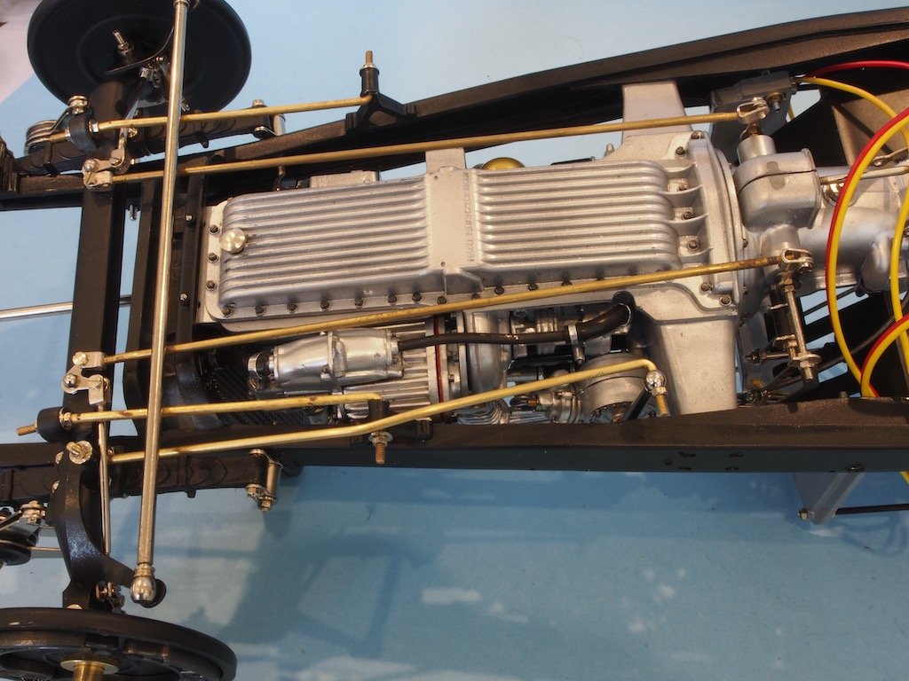
Chassis Bottom
The next item to address is the Oil Cooler and its plumbing. The usual adjustment of the plastic parts and subsequent painting precedes installation. The Oil Cooler is attached to the chassis bottom via two screws in the main floorboard. The position of the floorboard was previously adjusted during the body test fitting to ensure that the Cooler Filler pipe would correctly align with the appropriate hole in the fender.
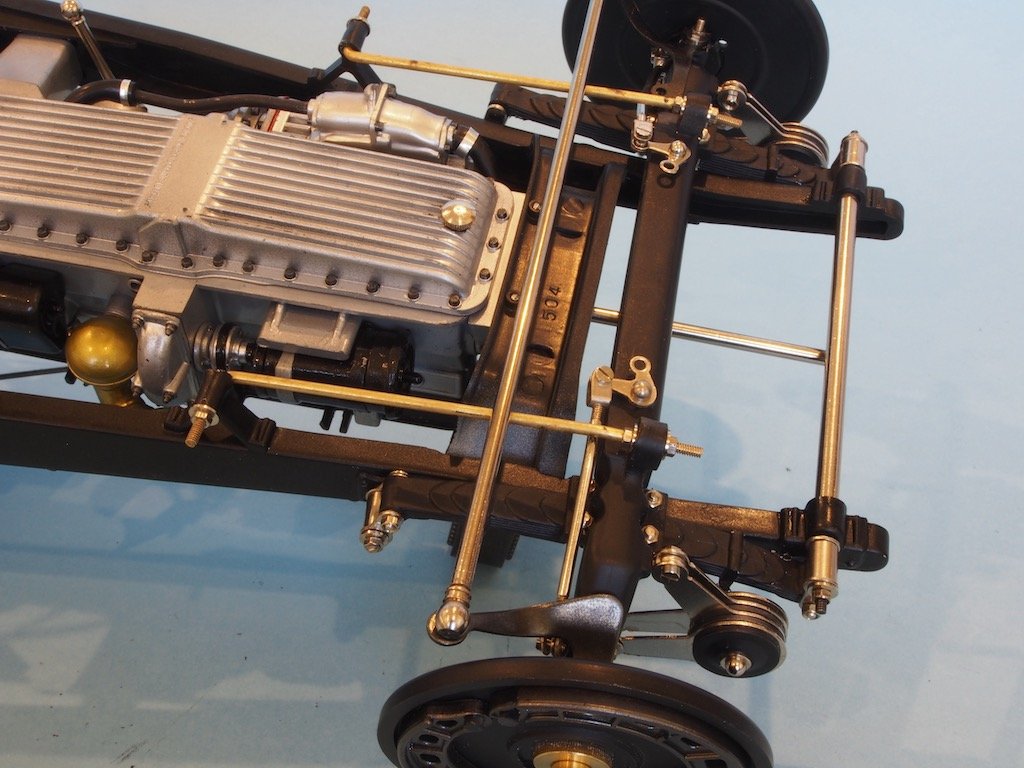
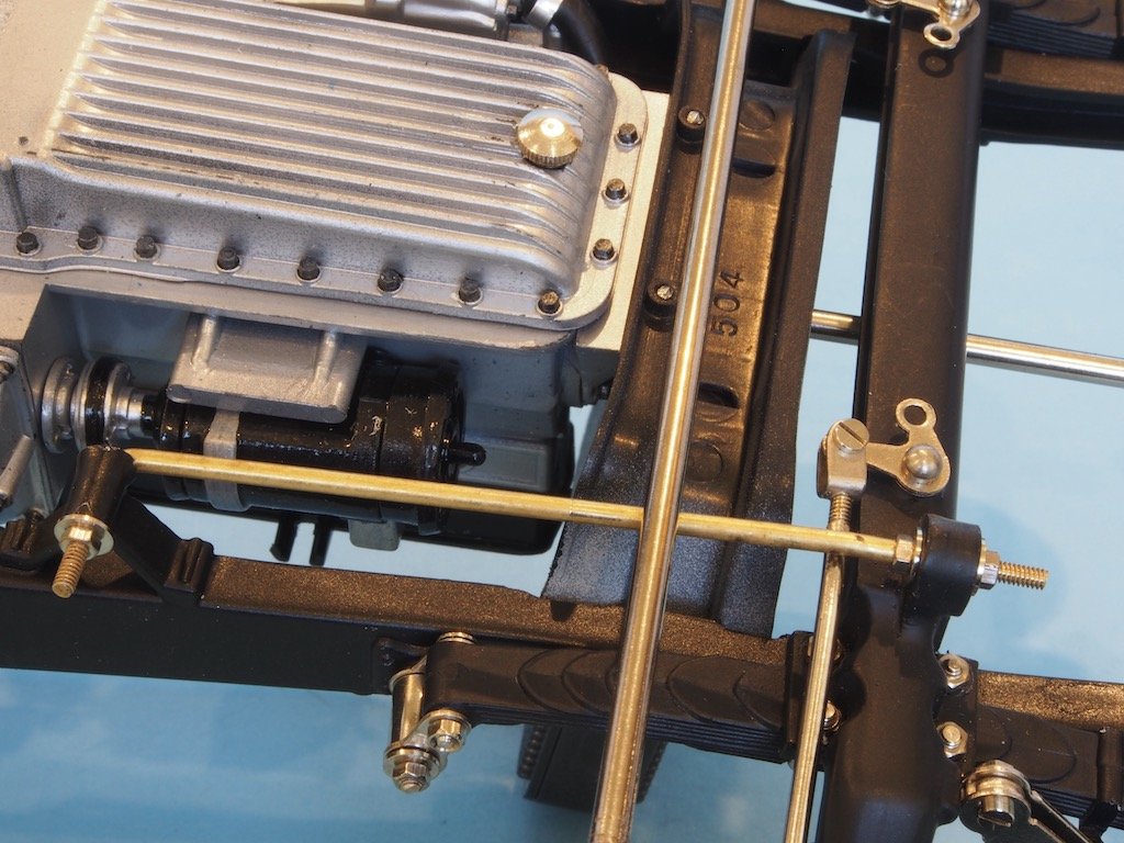
The pipework for the oil cooler consists of two brass rods that must be bent to shape according to some patterns provided in the manual. The right-side pattern is fine, although some of the bends are quite tricky to get just right. This line runs from the rear of the oil cooler along the chassis side and eventually into the engine. It’s the top line in the photo below.
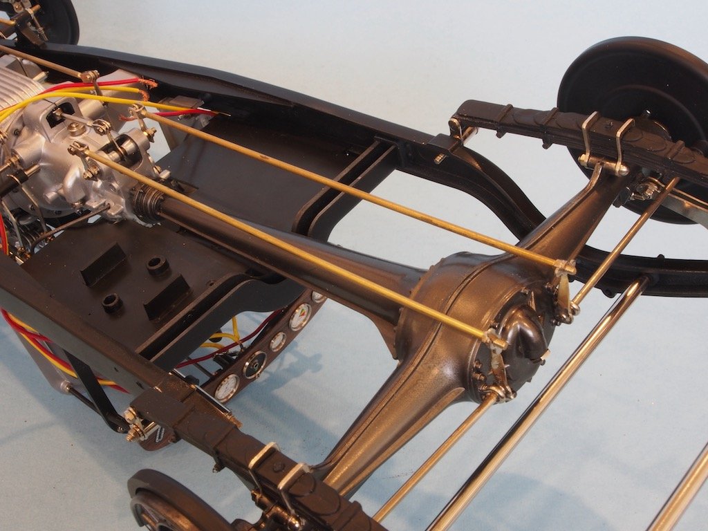
The pattern for the left side pipe however is incorrect. Fortunately, Paul Koo warns of this and advises how to go about shaping the line for a correct fit. It runs from the middle left side of the oil cooler around the transmission and into the engine.
Fuel Tank
The Fuel Tank is another item that requires a departure from the standard instructions. If fitted according to the manual, it will be too upright and the filler cap will not align with the hole in the bodywork. The fix is fairly simple in that it only requires leaving off the upper/forward mounting blocks. This allows the fuel tank to lean forward, which will then align the filler cap. Pocher addressed this in later versions of the kit by providing a differently shaped filler cap.
The fuel pump is also attached to the chassis via a mounting point on the rear floorboard and two copper lines are run connecting the pump to the fuel tank and carburettor respectively. An electrical wire (green wire in the photo below) is also run all the way forward along the chassis, then up through the firewall to connect to the back of the fuel gauge on the dashboard.
Exhaust System
The Exhaust system presents no particular problems other than the usual parts fit problems. To remedy this, the exhaust parts are not glued into the exhaust manifolds on the engine, thereby allowing the parts to self-adjust as they are fitted. In the photo below, the rear manifold appears to have shifted slightly during subsequent operations and will need to be readjusted in due course.
Continued next post...