


gjdale
-
Posts
4,825 -
Joined
-
Last visited
Content Type
Profiles
Forums
Gallery
Events
Posts posted by gjdale
-
-
19 hours ago, Chuck said:
Its literally the same half dozen or dozen cranks that do this with every change we make.
Reminds of an Admiral once quoted as saying, “I’ve been in this outfit for 40 years. I’ve seen a lot of changes in that time. And I’ve opposed every single one of them!”
Keep up the great work Mods/Admins - I’m sure any minor glitches with the changes will be overcome (or forgotten) in time.
-
I view cleaning the airbrush much the same way as sharpening a chisel - keep the tool clean/sharp and it will serve you better. Once you get used to stripping down, cleaning and reassembling the airbrush you’ll find it’s not that big a deal and you’ll become very proficient at it - much the same as gaining proficiency (and speed) at sharpening a chisel. If you get lazy about either task, the tool will not perform at it’s best and you’ll end up taking longer over the main task and likely with more re-dos.
-
-
He has an ebay store:
https://www.ebay.com/str/pocherphilesforum
But if you are after a kit, you’re probably better off contacting him direct via email as he doesn’t necessarily put these up on the web. He can usually source particular kits for you as well. If you’re interested I can PM you his email address.
-
-
You'll just need to be prepared to do a little bit of experimentation with air pressure, paint viscosity (ie thinning ratios), and air:paint mix through the brush. It sounds complex, but the only way to really get the hang of it is to just do it. After a while you will "just know" that you've got all the variables right.
-
Thanks for the friendly kick in the pants Chuck! 😀
Although my replacement parts all arrived safely a few weeks ago, I have been so absorbed in my non-ship project that I haven't gotten around to re-starting this one yet. I have been studiously reading others build logs though, and will re-start this one soon.....I promise.......I just need to get a round tuit. 😉
- Ryland Craze, Chuck and BobG
-
 3
3
-
-
-
If you are using an airbrush Bob, why not use it for the primer as well? If you are using Vallejo paints, their primers are also very good. I have found that thinning them 3 parts paint to 1 part (Vallejo) thinner works pretty well.
Although acrylic paints don’t have the “nasties” in them, they are still atomising the paint, so lung protection is always a good call.
-
Glad to see you haven’t given up on this one OC.
-
Sherline do have a quick change tool post in their accessory range.
https://www.sherline.com/product/2250-quick-change-tool-post-and-three-holders/
-
Congratulations on completing a really fine model Eric. She looks magnificent.

- Cathead, FriedClams, mtaylor and 3 others
-
6
-
Thanks everyone for the kind comments and likes.
Yves - not sure about the original wire colouring. I copied this from another model but there is likely some “artistic licence” as the colours need to be done in pairs due to the way they are fixed to the model. The Pocher kit has them all the same colour. I just wanted to use some different colours to add interest.
Also, I forgot to mention that the headlights on this model will be working. There is some preliminary wiring for this soldered to the back of the dashboard. The “switch” to turn them on will be the insertion of a key in the centre dash dial. In the photos you may be able to see some of the wiring (red and yellow) making its way from the dash down to each side of the firewall. One each of these pairs will go the right and left headlights, while a third set will lead to the battery box (which will be hidden but accessible).
BobG - yes, these kits are expensive and you need to be careful when buying. I strongly recommend contacting Paul Koo directly if you are seriously interested. Despite the wildly varying prices on eBay, Paul will charge you a “fair” price for whichever kit (and they do vary depending on the kit) and he will do a complete inventory for you if the kit is already opened (he does get some “factory sealed” kits occasionally - I’ve just bought a factory sealed Mercedes kit from him). He will also be able to provide you any missing parts - even factory sealed kits are known to have parts missing. He also provided me with the replacement cam covers for this Alfa model after I stuffed up the originals. In my opinion, you can’t go wrong with Paul - he is extremely knowledgeable, very helpful, prompt in his responses to queries, fair, and above all - HONEST. (Usual disclaimer - no affiliation, just a very satisfied customer).
- BobG, Old Collingwood, mtaylor and 7 others
-
10
-
Thanks for all the kind comments and for all of the 'likes' as well.
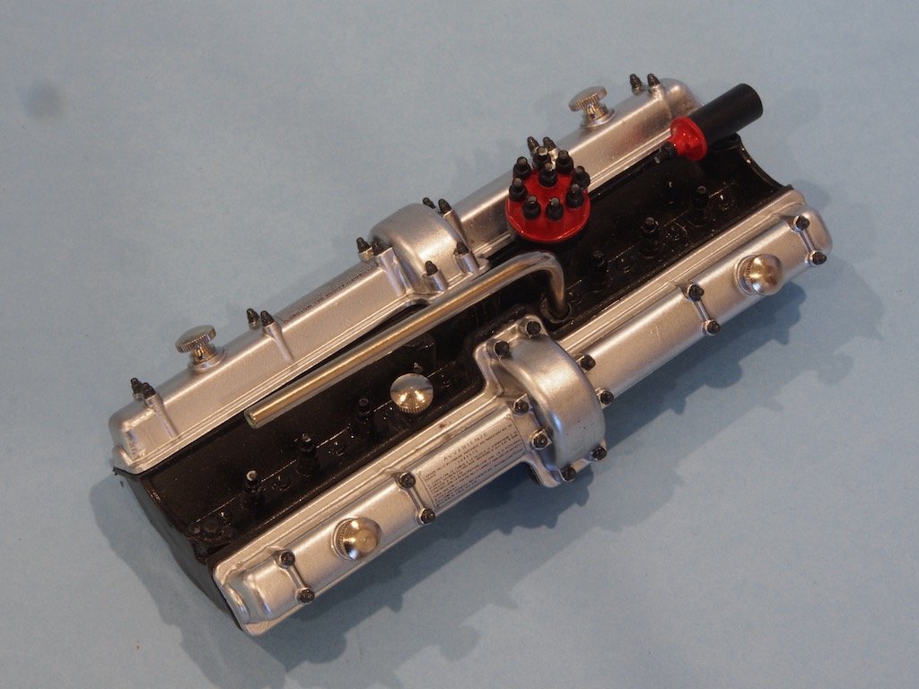
The replacement Cam covers finally arrived. After painting they were fitted to the Engine Head and two decals applied. These are aftermarket replacements for the stickers provided in the kit. Here is the assembled Engine Head – I have yet to fit the ignition wiring, which will be left until much later in the build as the Engine Head is still removable at this stage.
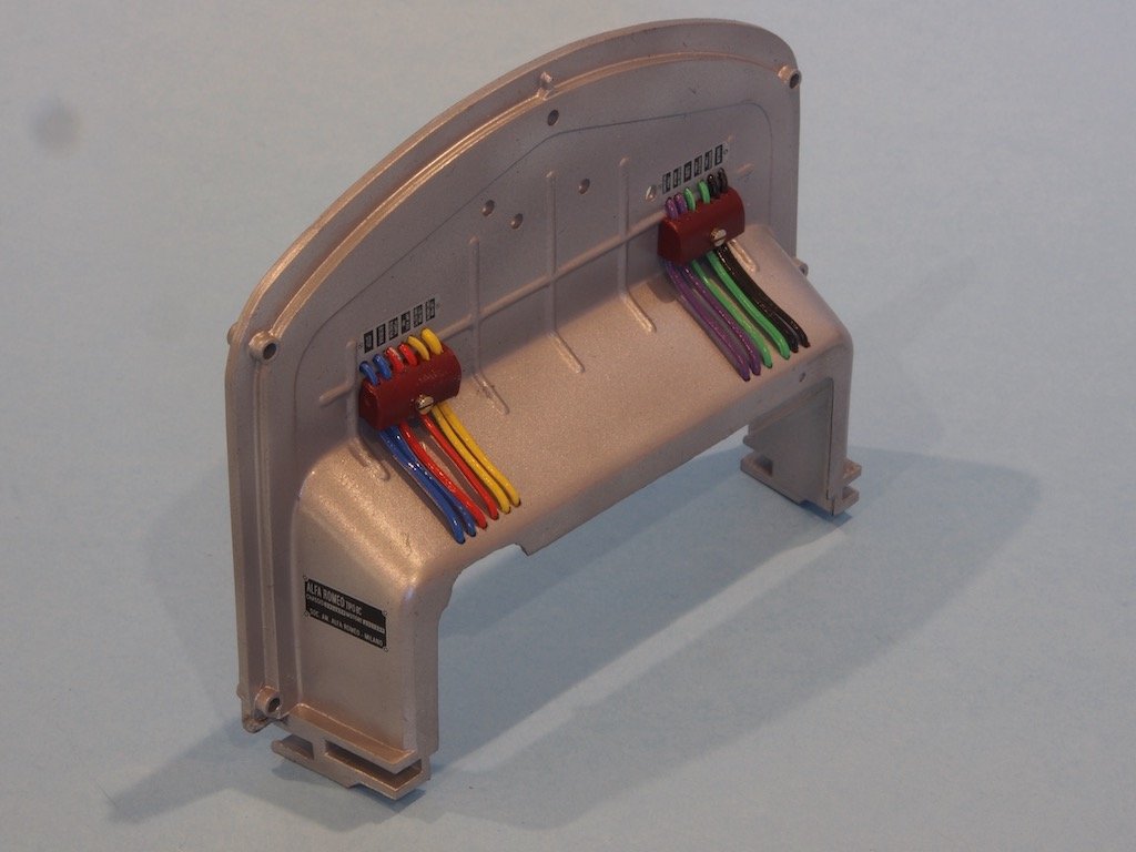
The firewall was also painted and then re-assembled with the modified wiring arrangement:
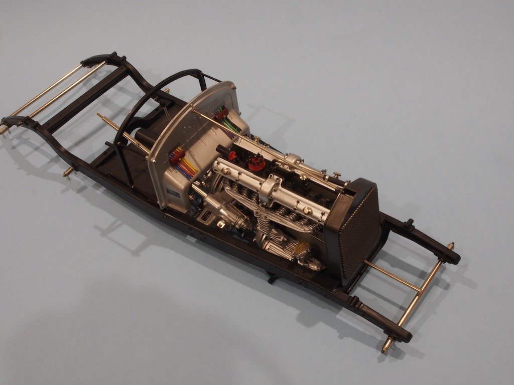
Once the remainder of the Main Frame had been painted, it too was reassembled – a relatively easy job thanks to all the test fitting and adjustment previously completed:
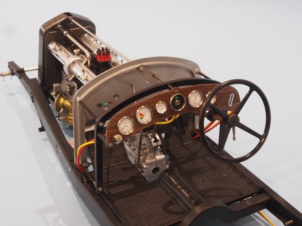
The Dashboard
The Dashboard presents no particular problems, although I opted to dress up the provided plastic piece a bit by making a real wood dashboard veneer using the plastic part as a template and some 1/64” thick walnut I had in my stash. Again, I replaced most of the kit provided instrument faces with aftermarket decals from Model Motorcars. While the decals look a lot better, they are very fragile and I think just about all of them broke in at least one place while fitting them. Not sure if it was my technique at fault, or the very, very thin decal material. Anyway, I managed to get the pieces re-aligned with a minimum of colourful language! Here is where we are at to date:
-
I definitely agree with everything Mike has said about Sherline. Although I’m in Australia, I bought mine through Mike’s Tools in the US - good prices, great service.
The only thing I would add is think about what you want to do with the machine/s. I personally think I get more use out of my mill than I do the lathe, although I do use them both. There is an option to buy a combination mill/lathe set-up from Sherline, but I would counsel against that in favour of two separate machines for slightly greater initial expense - otherwise you’ll invariably be set up for the opposite of the machine you need at the time!
As MIke said, accessories are likely to cost you more than the basic machines but you can add these as and when you have a specific need. Sherline do offer some very good package deals with the basic accessories - and you can buy these packages through somewhere like Mike’s Tools as well. (No affiliation here, just a very satisfied customer).
-
Nice work Chris - that looks to be a pretty good first layer of planking. A significant milestone in the build- congratulations!
You’ll find the second layer of planking much, much easier.
-
-
OC - I’m no expert in this, but have you considered using masking fluid? You can buy this in any art supplies store. You basically paint it on and it dries solid. When you’re done, it simply peels off. I’m thinking of this as an alternative to your blue-tac method.
-
Thanks Rick and Mike.
That’s a lovely looking finished model you have there Rick. Yes, that tail fin is going to be a challenge from what I’ve read so far!
MIke - I am not an experienced modeller in plastic by any stretch of the imagination. What is allowing me to do a half way decent job is the amazing instructions and photo essays from Paul Koo. I say, “go for it”.
- lmagna, Landlubber Mike, Egilman and 8 others
-
11
-
Thanks ken, Yves, Keith, Denis, Michael, and Mark for the kind comments, and to all of the'likes'.
The replacement Cam covers have at last arrived in country – they arrived in Sydney on 26 May. A week later and they still haven’t made it out of Sydney…. In the meantime, progress continues…
The Chassis
The basic sequence of assembly for the chassis is:
· Main Frame
· Radiator assembly and test fitting
· Test fit body parts
· Check engine position and decide whether to relocate the engine
· Paint the main frame
· Assemble the chassis components
Note that the above list involves a lot of test fitting, which implies a lot of adjustment, and the almost ‘throw-away’ line of deciding whether to relocate the engine!
The journey begins with the main frame itself. A number of adjustments are needed to allow the radiator cross member to fit properly. Failure to get this right will result in the front end being too wide and the body and suspension parts not fitting properly. It’s a relatively simple fix but once again, without Paul Koo’s guidance here this could end up a real mess!
The next issue to be addressed is the mounting arrangement for the firewall. On older kits (like mine) the firewall is attached to the mainframe by two screws accessed from inside the mainframe, making access extremely difficult because of the presence of the transmission. On newer kits, this problem was remedied by making through-holes in the frame and placing the bolts from the outside – a whole lot easier! Needless to say, Paul provides instructions for how to convert the older style kit to the new mounting arrangements.
The firewall is also modelled incorrectly in that only four wires for each of the two fuse boxes are used, and their routing is also incorrect. Following Paul’s advice, two new (slightly larger) fuse boxes were scratch built and holes drilled for the correct wiring. I bought some rainbow ribbon wire from my local electronics store and stripped this down to provide some different coloured wiring.
The next issue is the fit of the radiator and the cross brace. An incorrect radiator position will affect the fit of the front nose. When properly positioned, the radiator must be slanted to the rear when viewed from the side. The radiator brace, which joins to the firewall, must be horizontal (ie parallel to the main frame) however the brace is tightly fixed to the radiator at an angle of 90 degrees. If this is not fixed, when the brace is attached to the firewall, it will push the radiator into a vertical (incorrect) position and once again cause fit problems with the front nose and hood. The fix for this is to attach the brace to the radiator, and then apply heat from a soldering iron to the metal brace. The heat will then start to melt the plastic surround at the radiator mounting point, which allows the brace to then be lifted up about 20 degrees and held there while the plastic cools. Now, experienced plastic modellers are probably quite familiar with this type of technique, but it was a first and somewhat nerve-wracking time for me. It did however, work exactly as advertised.
The next issue is the hole in the bottom of the radiator for the engine hand crank. With the radiator mounted correctly at a slight angle, the hand crank will not pass through the hole in the bottom of the radiator assembly. This one is an easy fix, requiring only that the hole be slightly elongated on the rear side.
Once all of these issues had been addressed, the engine and firewall could be assembled to the main frame.
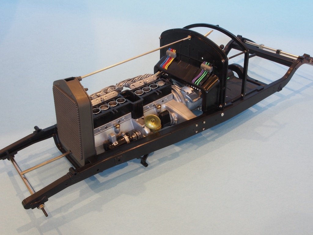
With these issues addressed, it was time to test fit all of the body parts, starting with the main body. The first issue to be addressed is that the main body must fit flush against the main frame. However, there are a couple of (unnecessary) raised moulded details that prevent this, along with the presence of the bolt heads for the engine mount and firewall (see photo above). The moulded details are easily taken care of by sanding flush. The bolt heads on the other hand require a different approach – enter the soldering iron once more. In this case, a hot soldering iron is touched to the bolt heads and once the plastic starts to melt, the bolt is pushed into the plastic until it is flush with or just below the surface. As it goes in, the plastic moulds itself around the bolt thread, forming additional threading inside the now longer hole. It’s a brilliant technique!
There is still some additional tweaking required to the main body plastic, although mine didn’t seem to need as much as some others clearly do from Paul’s descriptions/pictures.
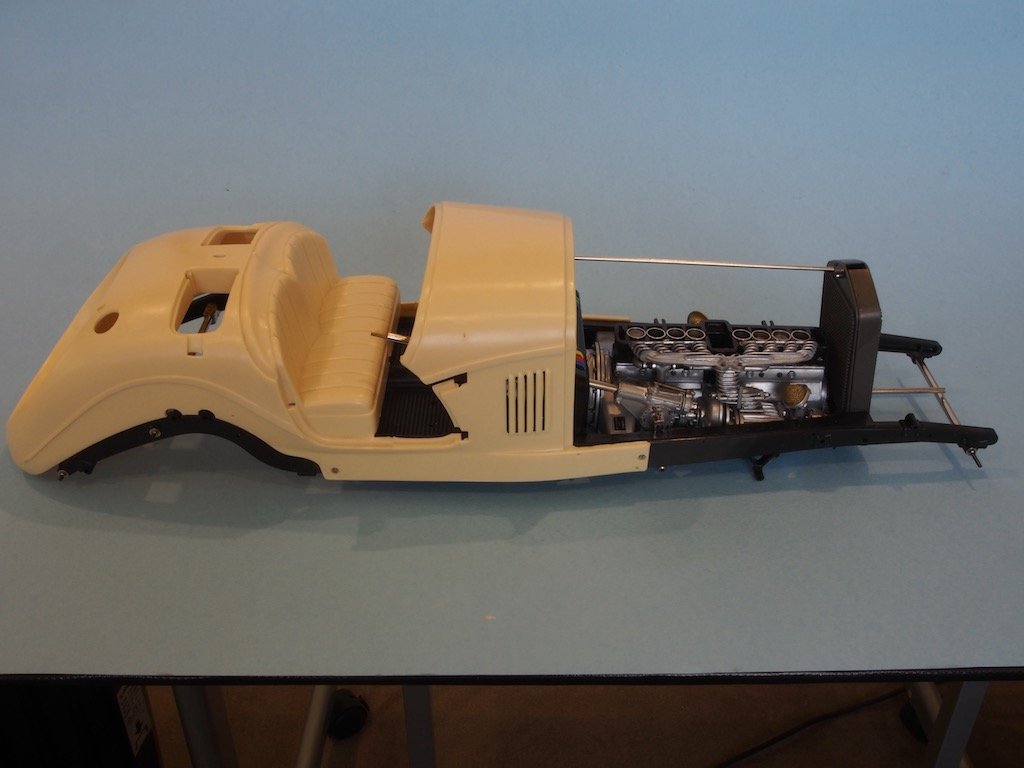
With the main body in place, the fenders can be test fitted. There is a fair amount of clean-up required on these, and the two of the mounting holes are misaligned on the main body, requiring new mounting holes to be drilled and threaded. Two additional mounting points are also created by drilling and using the “melting method” to drive screws right through the main body and into the main frame to close up some residual gaps. Again, this method worked really well. The front nose was also adjusted to allow it to fit properly over the radiator. Then further adjustments to the fenders were required, including removal of a significant amount of material from the front ends, to allow them to fit properly around the front nose.
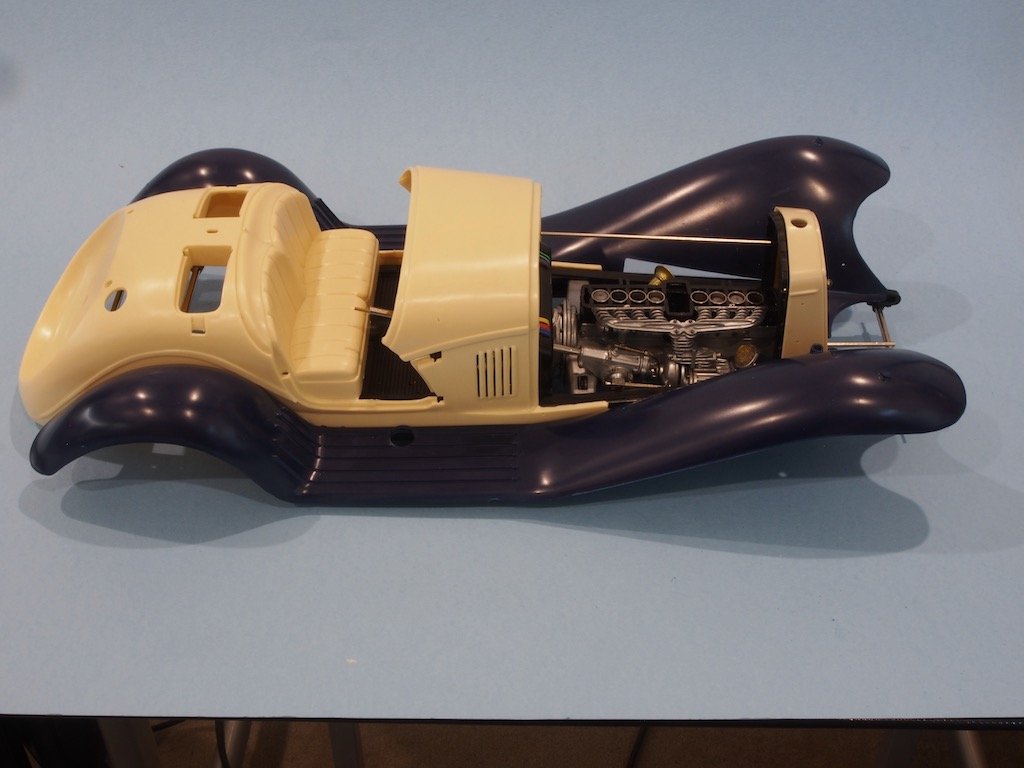
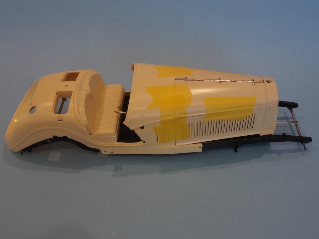
Once the fenders were fitted correctly, it was time to remove the fenders and main body again in order to test fit the engine hood panels.
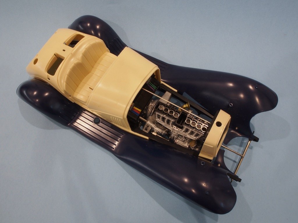
Paul’s instructions suggested that quite a bit of finessing would be required to make the side and hood panels all fit together with the main body. I must have gotten lucky here as mine needed only a very slight adjustment to allow them to fit properly. In the photo below, they are held in place with masking tape and placed back on the mainframe to check for overall fit. As you can see, all seems to be well with no significant gaps around the front nose.
The final tasks in test fitting the body panels included the two covers (just behind the seats), the doors, and the rear end (moulding line). Of these, the only tricky part was the doors, which required quite a bit of very fiddly adjustment. I forgot to take any progress photos of these, but they do fit now.
Once all of these adjustments were made, the whole lot was disassembled again, including removing the engine and fire wall, so that the main frame and firewall can now be painted.
The issue of relocating the engine is one of considerable debate. According to Paul Koo’s notes, the problem arises from part of the model being designed with the engine in its current placement, and part being designed with the engine approximately 10mm further to the rear. Paul offers four options to remedy this – a 10mm rearward move, a 5mm rearward move, a 2 mm rearward move, and no move. Of these, he recommends the last option – no move. Any move of the engine rearwards will result in significant further changes being required as the model progresses. The no move option involves omitting one part and accepting that the hole in the top of the radiator will not be aligned with the hole in the top of the front nose (a detail that will not be visible on the completed model). The part is a threaded base that attaches to the top of the radiator and passes through the front nose. If it is inserted with the engine in the current position, it will pull the radiator into a vertical position again, causing subsequent fit problems. By omitting this part, the radiator can stay as is, the radiator cap then subsequently gets glued to the front nose, rather than being attached by a threaded component.
I’ve decided to go with Paul’s recommendation of ‘no move’ – this build is hard enough as it is without adding further complications!
Next up, painting the mainframe and re-assembly.
-
-
-
You might also like to check out Vanguard Models. Chris Watton, who is also a member here, has just added two nice little models to his range, that are specifically targeted towards beginners. His kits use quality components, are exceptionally well designed, and come with probably some of the best instruction manuals going. His express desire in creating these offerings was to provide newcomers with a positive experience that would encourage them to stay with the hobby. You will find some excellent build logs on the site here if you want to preview what building them will look like.
New from Brisbane, Australia
in New member Introductions
Posted
Welcome to the forum from the Nation’s capital Jii. You’ll find there are quite a number of us Aussies here. Regarding first kits, although I’ve not built one, there are some nice offerings from Vanguard models available that are specifically designed with beginners in mind. There are also a couple of reviews of these kits here on the forum, and a few build logs underway. Although UK based, so postage will take a while in the current COVID environment, they could be worth waiting for. I don’t think you’ll find better sets of instructions anywhere.