


gjdale
-
Posts
4,872 -
Joined
-
Last visited
Content Type
Profiles
Forums
Gallery
Events
Posts posted by gjdale
-
-
-
-
What a wonderful and interesting piece of work. Please do continue with the updates - this will be fascinating to follow!
- popeye the sailor, lmagna, mtaylor and 2 others
-
 5
5
-
-
-
There are a number of “how to” videos on YouTube for making your own spray booth, including the fold up variety. After watching some of these, I recently made my own from poster board and duct tape (for hinges). Works great, folds flat for storage, and is light as a feather.
-
-
Looks like a fascinating build - I’m in. 😊
- mtaylor, Jack12477, Edwardkenway and 3 others
-
6
-
-
Mike,
Thanks for dropping by. Nice to know there are a few more Pochers out there in MSW land. I also have two Rolls (the 1932 Sedanca Coupe and the 1934 Torpedo “Star of India”), with a Mercedes “Rumble Seat” on the way soon. Glad to hear you’ve got Paul Koo’s DVD - I certainly wouldn’t have gotten this far without it - they are that good! Best advice I can give you is to do a thorough parts/inventory check using Paul’s parts inventory photos and if you find any missing parts (quite likely, even with a “factory sealed” kit) contact Paul directly as he will likely be able to provide the missing part(s).
As for airbrushing, I’m a relative novice but am not having too much trouble. I’ve learnt the secret is to find the “just right” combination of air pressure and paint flow for the particular paint you are using. I’ve been having some good success with the Vallejo Metal Colour series so far.
My build is on “pause” for the moment as I await delivery of two spare parts from Paul, and a new shade of red paint from a “local” supplier. Both are on the way, but the postal system is understandably a little slow at the moment.
- Script, Canute, Landlubber Mike and 7 others
-
10
-
Congratulations on completion of a fine build Jesse.
- JesseLee, popeye the sailor, Canute and 1 other
-
4
-
Looking good Chris. Proportional dividers are a really useful tool to have in the tool kit.
Once you get this first planking finished, sanded and filled, and sanded again, you’ll find the second planking much, much easier - mainly because you’ll then have a solid surface to work on, but also because the second planking is so much thinner and easier to shape.
-
Welcome to the forum. If you don’t get an answer to your question on RC here, you might try asking on the RC boats forum. I’ve seen a lot of Smit Rotterdam builds over there. Here’s a link:
https://www.rcgroups.com/scale-boats-55/
-
-
Looking good Bob. Which particular Vallejo Model Air Red colour is it that you are using? (I mean what is the number designation of that particular shade?) I find it very difficult to tell from their colour charts how a particular colour is going to come out and end up buying several to test before settling on one. I like your shade, so might save myself some testing!
-
6 hours ago, Riotvan88 said:
I need a tool to cut precise 90 degree cuts to make the blocks to fill my Hul
The only tools you really need are saw of suitable size, a square, a knife and a shooting board (which you can also make). Use the knife and square to mark your cut line on all four sides. Then saw just on the waste side of your cut line. Use a shooting board to clean up back to your knife line. You can use either a plane (best) or a sanding block on your shooting board to trim back to the knife line.
You could also make your own mitre box by simply making an accurate cut with your saw part way through one piece of wood and then gluing/taping/screwing a second piece of wood to this as the platform/bed. Hold this in your vice and you have a mitre box with no play.
There are a number of videos on YouTube about these ideas. My favourites are those by Paul Sellers. Matt Estlea is also very good. Paul Sellers demonstrates making both a mitre box and a shooting board, as well as using and cutting to a knife line.
-
Beautiful work Ben, as always.
- Trussben and FrankWouts
-
2
-
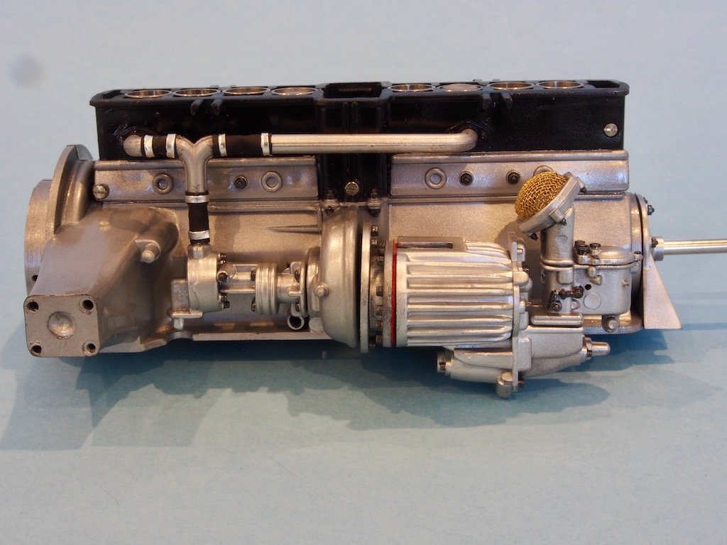
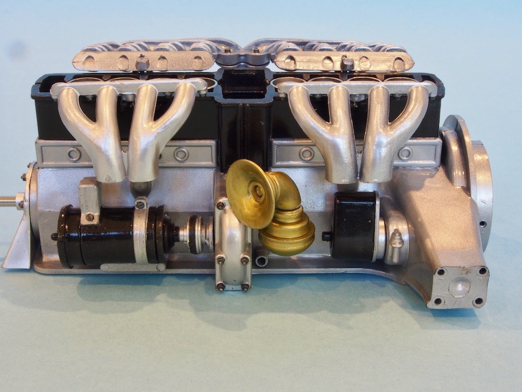
Engine Block Assembly
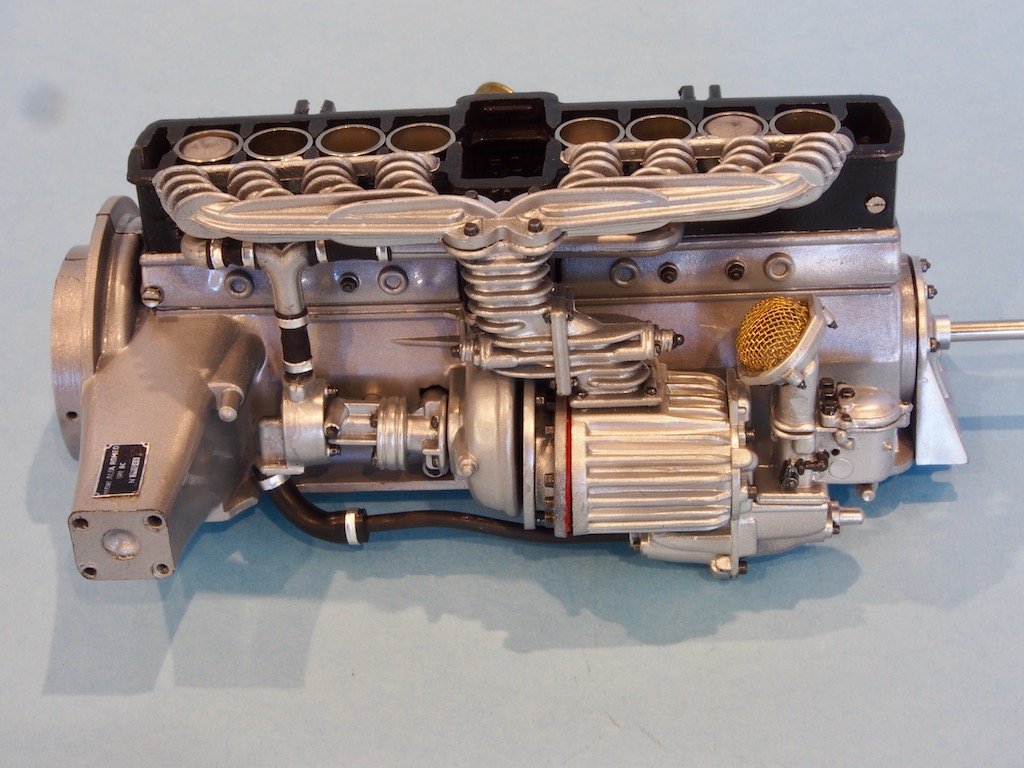
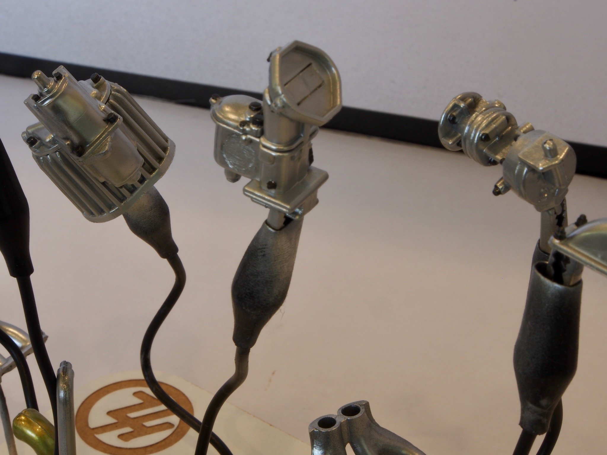
Assembly begins by attaching the external components to each side of the engine block. Here is the right side, showing the carburettor, supercharger, water pump and water pipes.
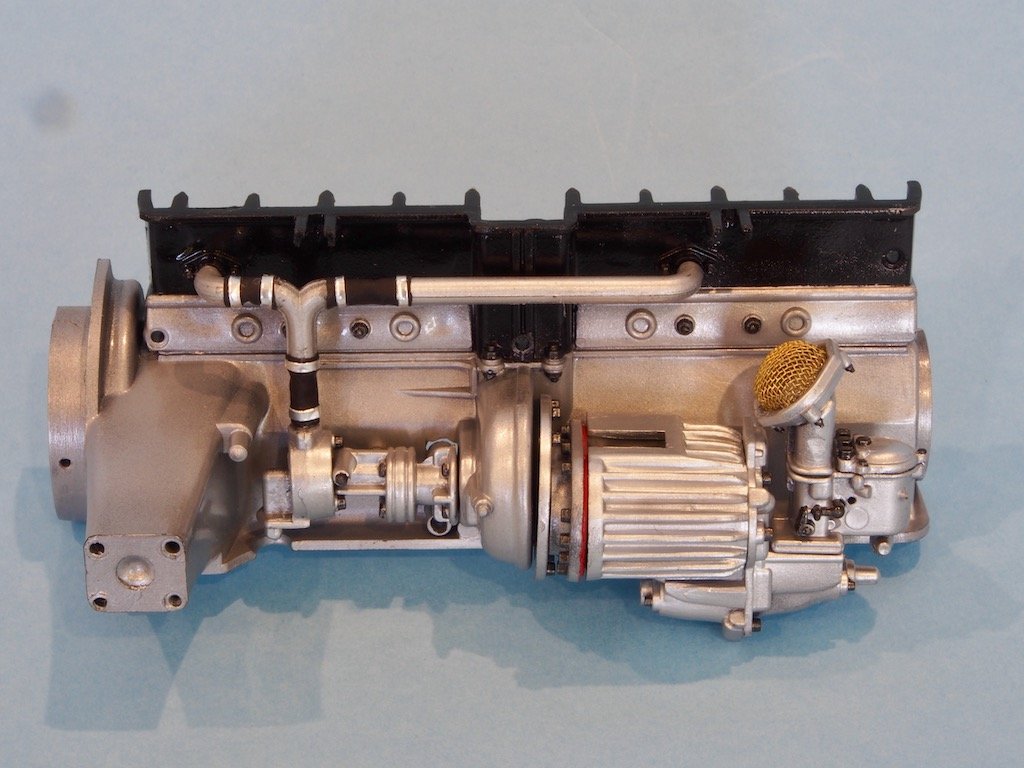
The trickiest part of this assembly was the water pipes. There are two horizontal “arms”, and a vertical “Y-piece” connected to each other with short lengths of rubber hose. The lengths of the solid components had to be adjusted as they were all too long to fit together in the space. The kit-provided rubber hose was so old that it had turned solid and brittle, so this was replaced by some aftermarket plastic tubing from Model Motorcars. The hose clamps were simulated by small strips of aluminium tape.
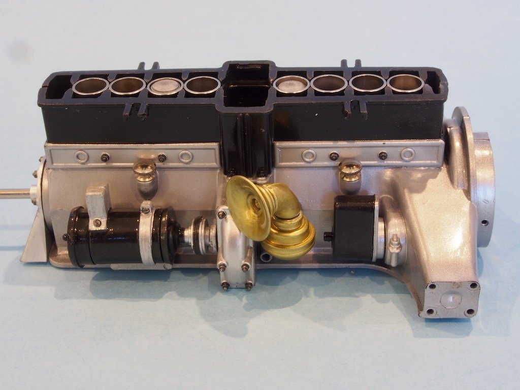
Here is the left side showing the generator, side cover, horn and starter motor, along with two oil filler caps.

The horn is made up of three components – two brass pieces joined by a plastic “elbow”. For consistency, I painted all three parts the same colour (Vallego Metal Colour Gold). The generator was one of those parts where the fit was so bad that the mounting holes on the engine block had to moved during the pre-fitting. The oil filler caps also required their repository openings significantly adjusting.
Once the main external components were fitted, the crankshaft could be made up.
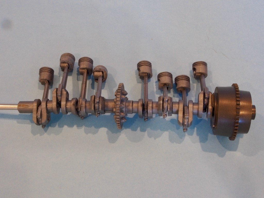
The individual parts were designed to snap/press fit together, although they needed a fair bit of adjustment to get them to fit. The main linkages were glued once joined linkages, being careful not to interfere with the movement of the connecting rods. The piston heads are simply set in place with an internal pin that goes through a hole in the con rod. The whole assembly could then be placed carefully in the left half of the engine block.
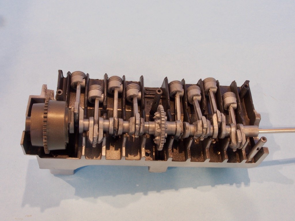
The individual metal cylinders were then carefully set in place. It’s important to get these the right way up so that they sit properly in place and allow the engine block to seat securely around them.
The right hand side of the engine block was then carefully placed on top, and the four retaining screws put in place, while standing on my head, rubbing my tummy and holding my tongue at just the right angle!!! I found that even with the screws nipped up securely, there was still a tendency for the top of the engine block to pull away each side at one end, so I provided some extra assistance in the form of a small amount of CA glue at that spot and clamped it gently overnight.
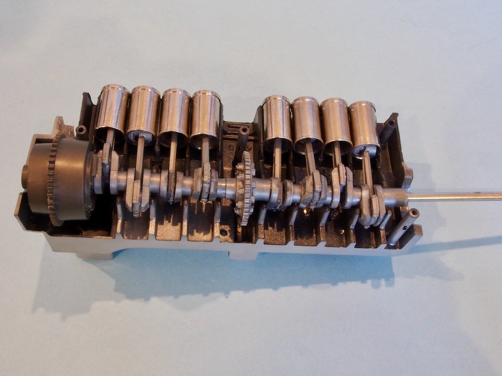
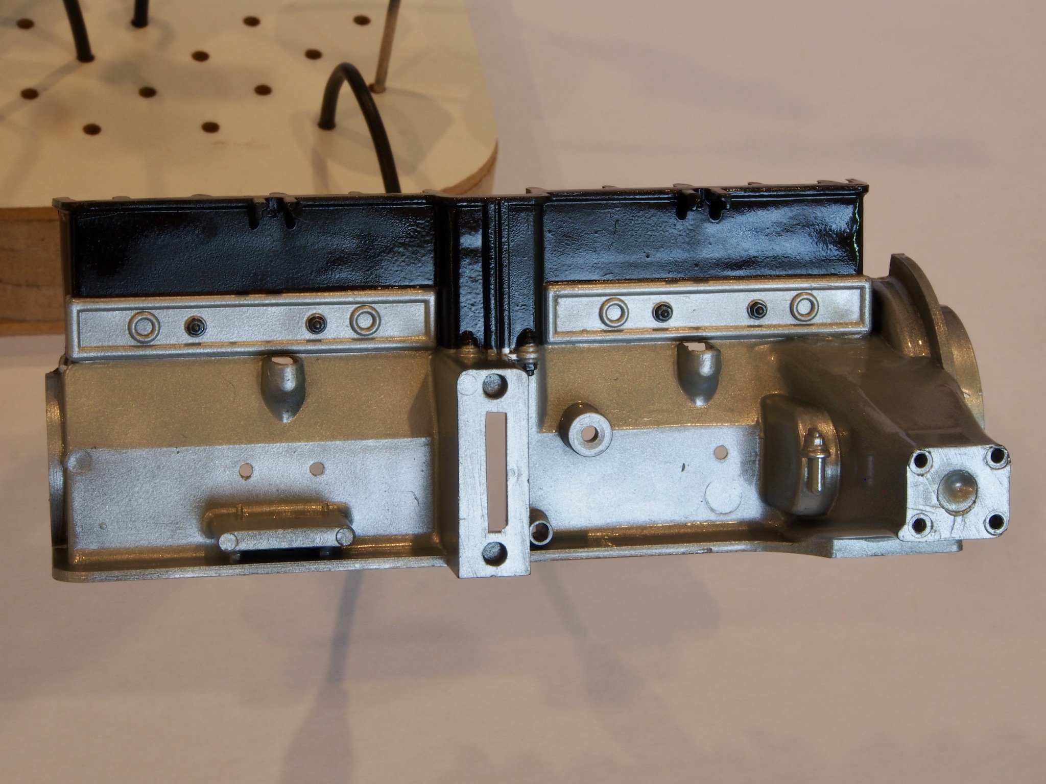
Here are a few pictures of the engine block as one unit.
In the second picture you can see the tops of some of the pistons within their cylinders.
The front end piece was also added at this stage.
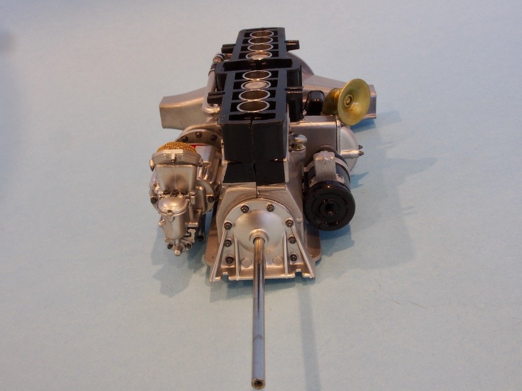
And if you turn the crankshaft, you can watch the pistons moving up and down within the cylinders. Cool……
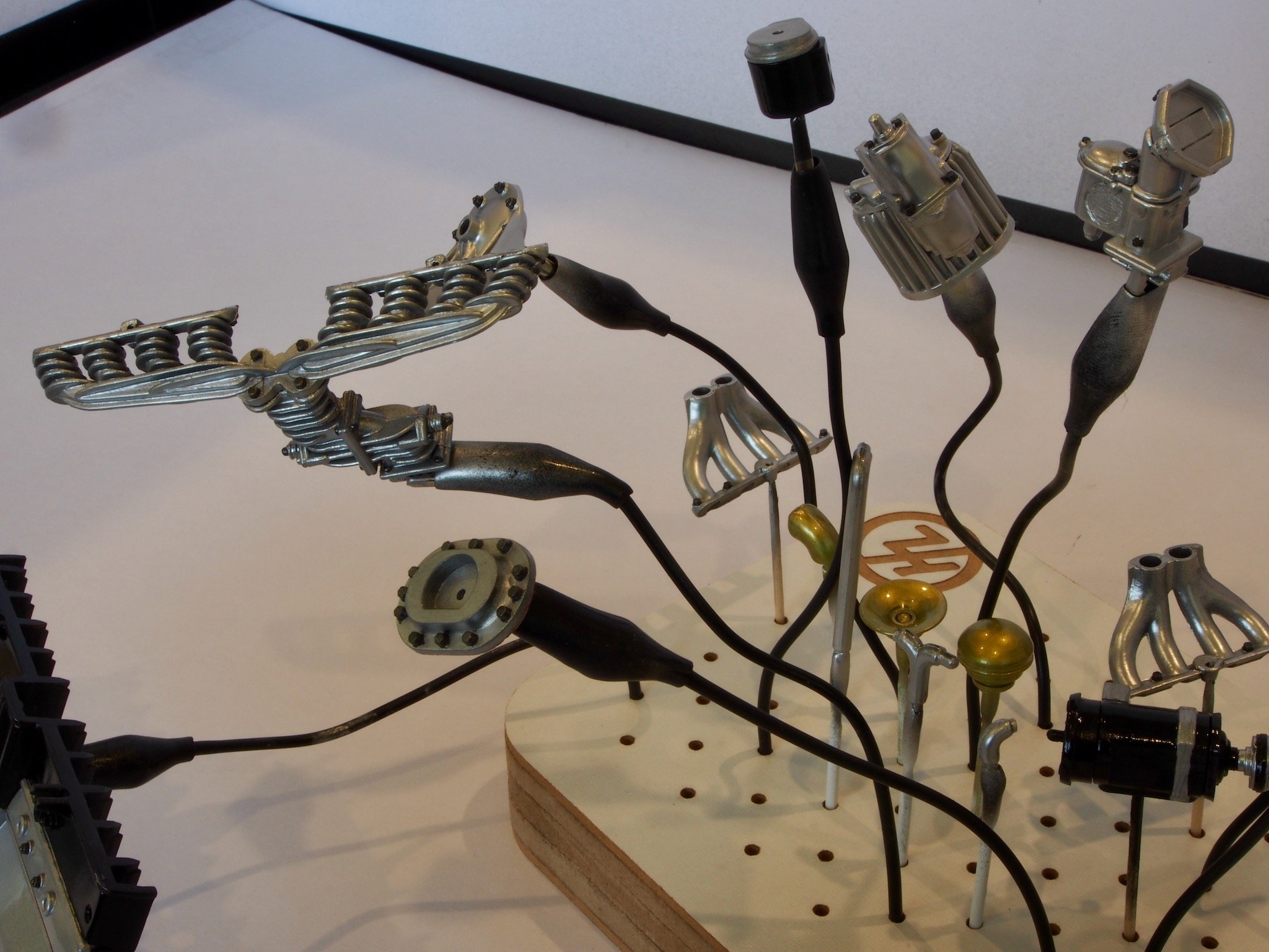
The inlet manifold could now be fitted. It had to wait until the two engine halves were together so that the centre retaining screw wasn’t obstructed. Of course, if you were just following the kit diagrams, you wouldn’t work this out until it was too late. Thankfully, Paul Koo’s instructions not only alert you to this, but also advise on a modification to how the inlet manifold joins the top of the supercharger to make it possible to fit at this stage. So here it is in place.
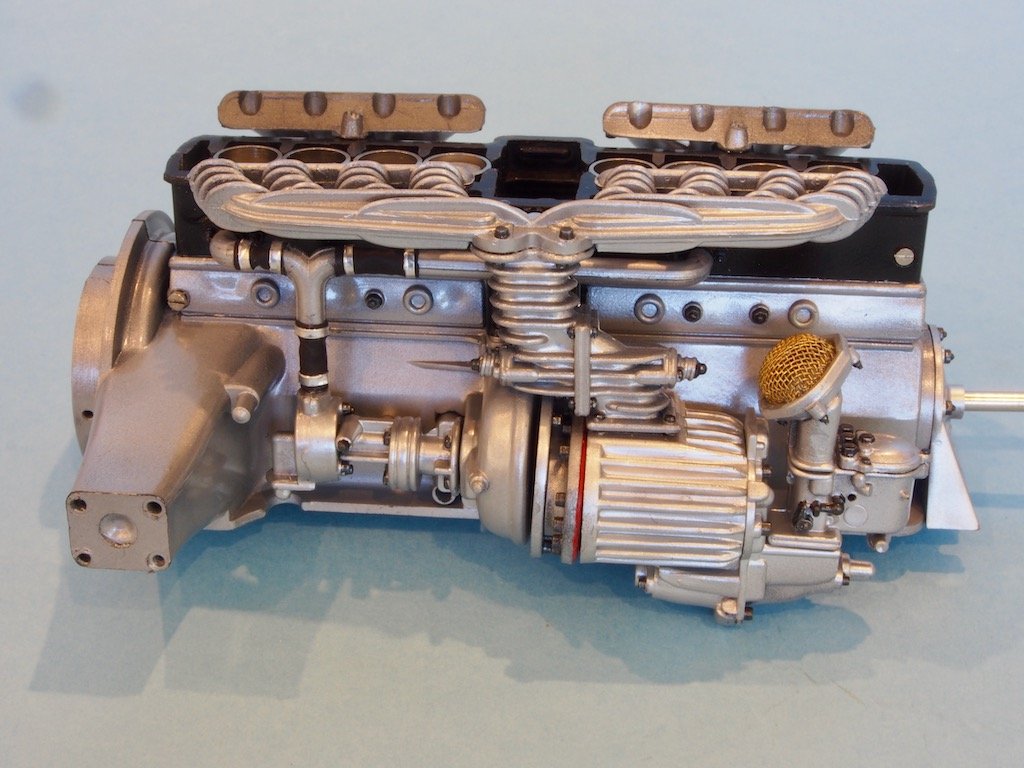
The exhaust manifolds were temporarily fitted for the photo shoot, but won’t get permanently fitted until much later, when the rest of the exhaust system is installed.
Finally, the bottom water pipe was fitted. This was a bit tricky as the pipe needed to be bent to shape in order to fit properly without interfering with other components at a later stage. A sticker was also attached at this point. It’s one of those extra touches that add that little bit of extra realism.
I just have the engine bottom pan to install now before commencing work on the Engine Head.
-
Thanks OC and Ryland - welcome aboard.
Ryalnd, you should definitely dig your Monza kit out again. Again, if you get hold of one of Paul Koo’s DVDs, you will find it a lot easier to finish your model. Seems there are quite a few Pocher kits lurking in people’s cupboards here on MSW - lets see if we can get some resurrected.
-
Thanks Ken - welcome aboard.
-
Hi Egilman,
Welcome aboard. You should definitely have a go with your Fiat. If you get hold of one of Paul Koo’s DVDs, you will find that even the most intimidating aspect can be overcome with a little guidance.
-
Hi Yves and welcome to the build. I hope this will rekindle your desire to build your own kit. Thanks for the tip on Model Motorcars, though I had already found them back when I was researching. I may have already purchased or two items from them.......😎😎😎
And don’t worry, I won’t be rushing this one. Heck, it took me more than three years just to open the box! 😉 Seriously though, the posts above represent about six weeks work on and off.
-
Hi Jim,
Yes I do indeed recall our conversations of a few years back. Nice to hear from you and welcome along for the ride. Interesting that you have the MB 540K Roadster kit. I was considering that one but opted instead for the “Rumble Seat” version, which I am acquiring through Paul Koo.
- Old Collingwood, lmagna, Egilman and 5 others
-
8
-
The main engine block in the street variant of this car was aluminium with a cast iron cylinder head. I sprayed the majority of the engine components with Vallejo Dull Aluminium and then went back and hand painted the simulated bolt heads with Vallejo Gun Metal. The main block was sprayed with a two-tone effect using Dull Aluminium and Black for the cylinder head. Everything was then given a coat of Metal Varnish to finish. Here are a few photos to show the overall painting, along with some close ups of the various components.
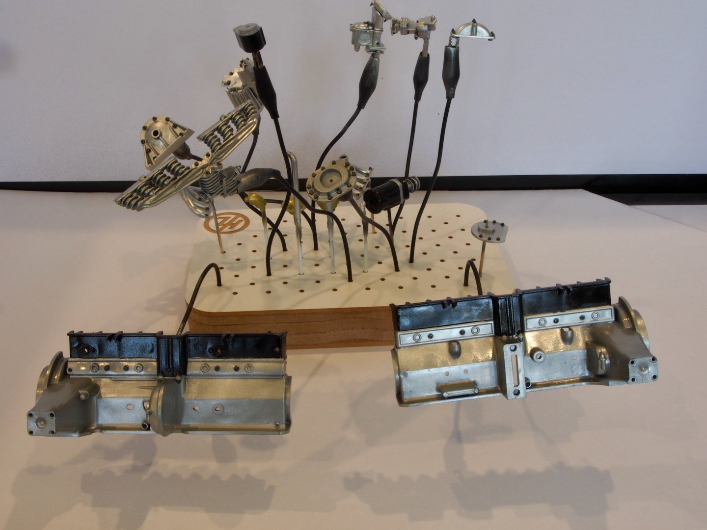
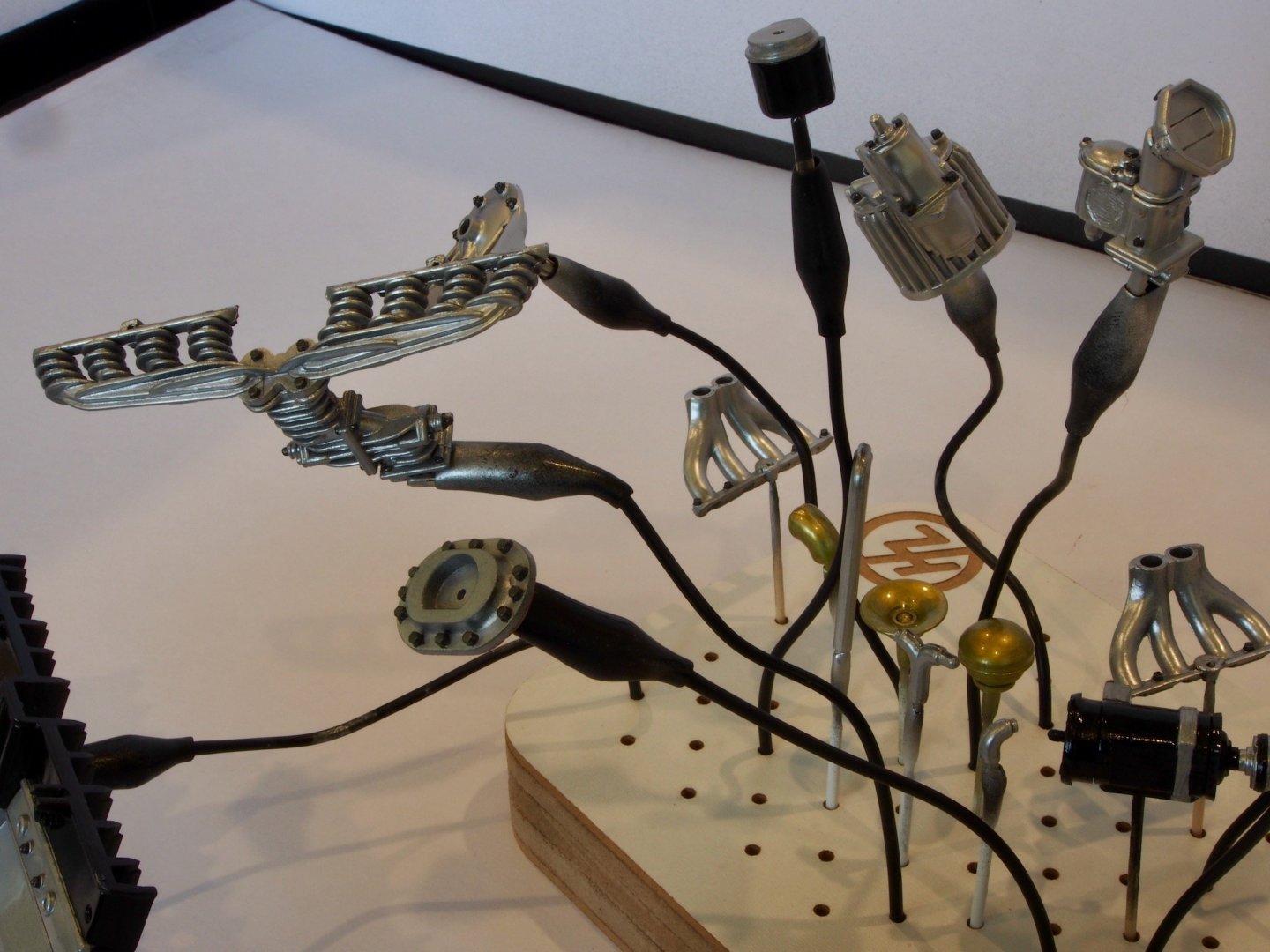


These components are now ready for assembly.


Alfa Romeo Spider Gran Touring by gjdale - FINISHED - Pocher - Scale 1:8
in Non-ship/categorised builds
Posted · Edited by gjdale
It's been a while since I updated this log - the reason will become apparent shortly!
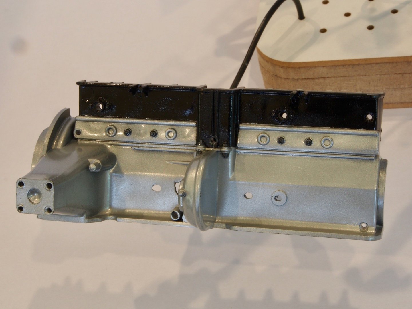
The Engine Bottom Pan was painted with the airbrush and the bolt heads hand painted. It is meant to be removable to provide access to the engine parts, being held on by a clip on the other side of the oil drain plug. I decided to add a small dab of CA glue to the opposite end to make it a little more stable (I won’t be taking this apart!)
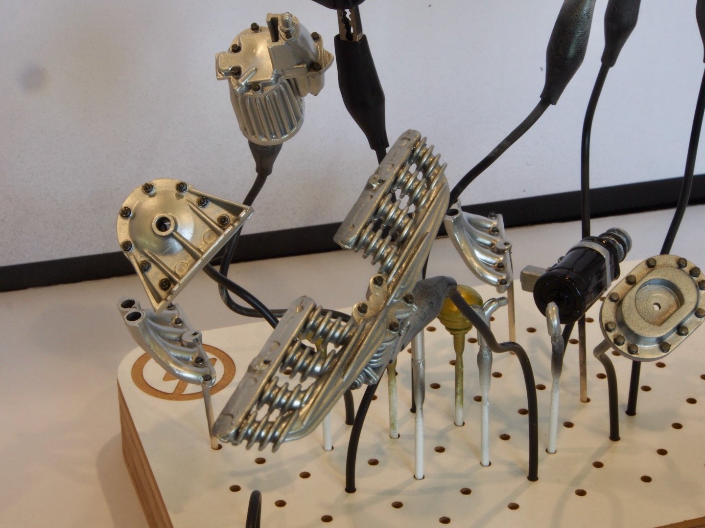
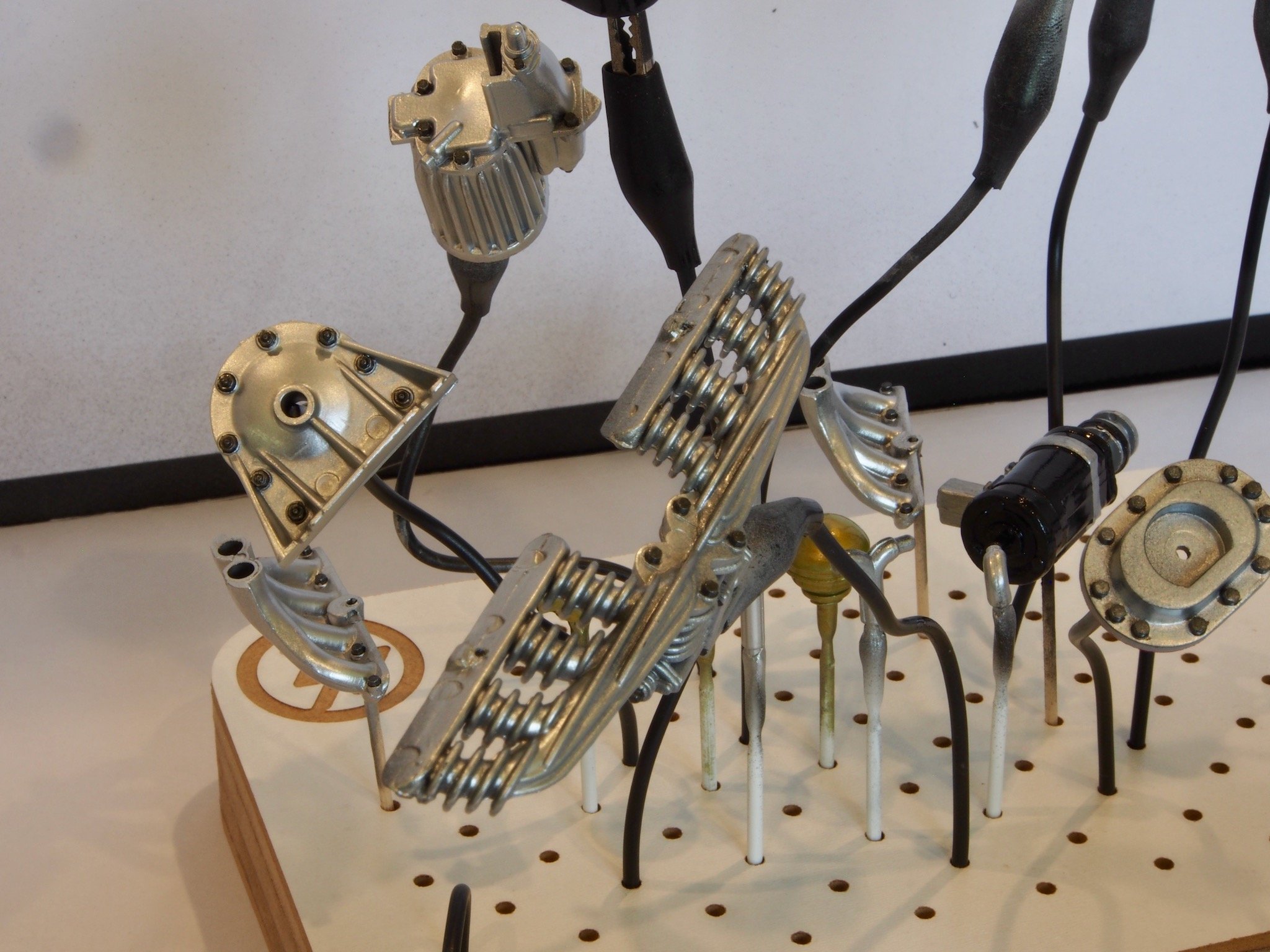
The Engine Head
The Engine Head is a fairly straight forward affair – at least it should be. All that is required is to assemble and install the Cam Shafts, Distributor, Ignition Coil, Oil Filler Cap, Water Pipe, and Cam Covers. As with the rest of the Engine, it is a case of test-fitting, adjusting the fit, then dis-assembling, painting and re-assembling.
I had a bit of an oops when trying to adjust the fit of the Cam Covers. Let’s just say I got a little too enthusiastic with a heat gun and am now waiting on replacement parts to arrive! This is why I haven't updated in a while.
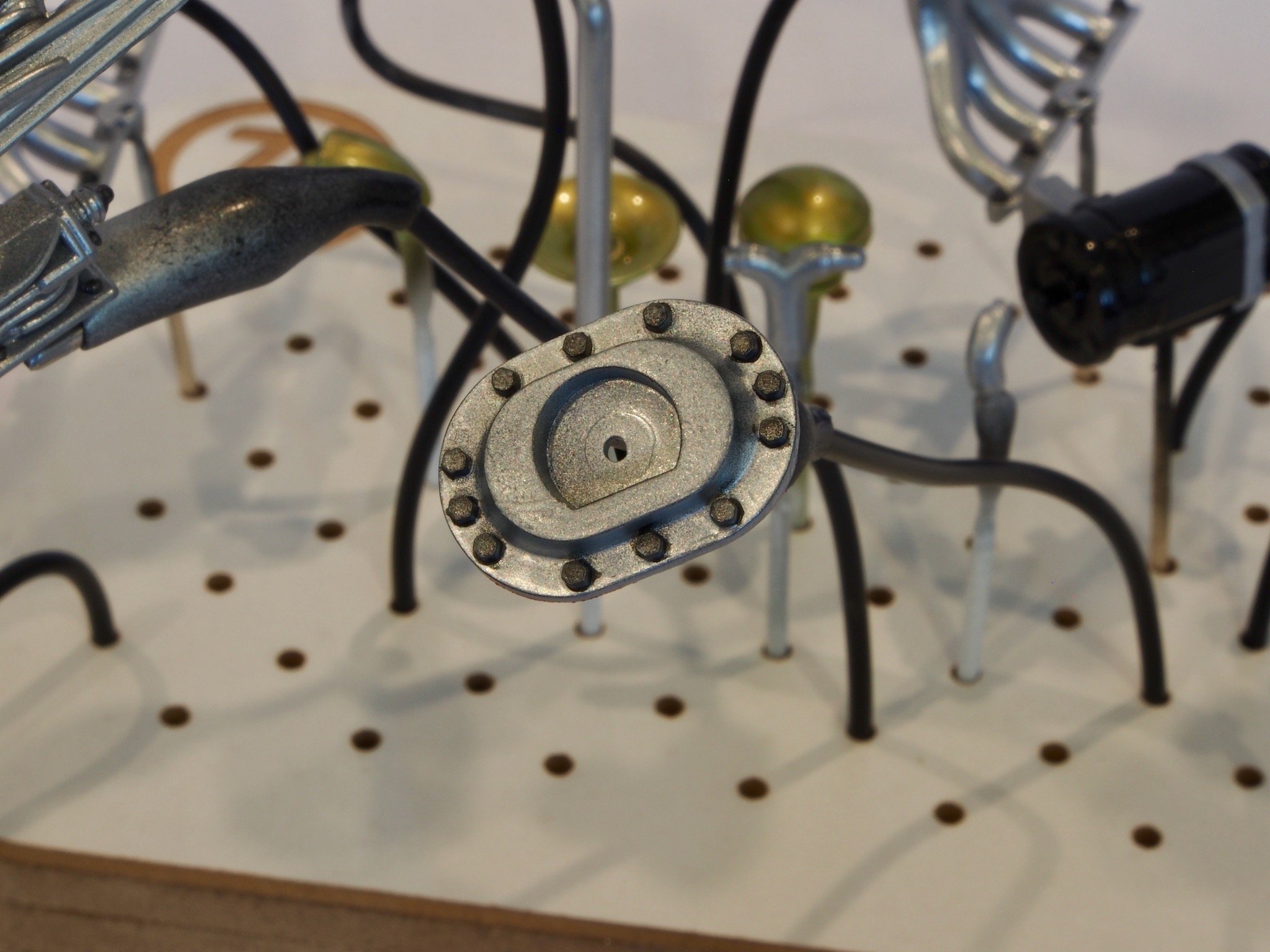
In the meantime, I decided to upgrade the kit a little by adding some aftermarket ignition wire boots from Model Motorcars. I believe these are 3-D printed, though I’m not certain. They are supplied on a plastic card base and need to be cut free. Here is the remains of one card.
These needed to be painted black prior to installation, so after cutting them free individually, I then put some double-sided tape on a wooden stirring stick and placed all of the boots on the tape. This gave me a “handle” as well as securing these tiny items while they were sprayed with the airbrush. I finished them with a satin clear coat and then attached them to the cylinder heads, distributor cap, and ignition coil.
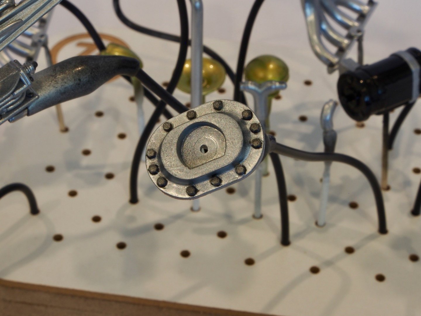
Here is a picture of the Distributor Cap and Ignition Coil, complete with boots.
And finally, here is a picture of the engine head with all parts temporarily in place, bar the Cam Covers. The ignition wires / spark plug leads will be added at a later date.
I can’t finish off the Engine until the Cam Covers arrive. They were posted from California on 15 April and were last tracked by USPS in Los Angeles on 16 April. With the current postal situation due to COVID19, it may take some time for these to turn up. I may move on with the Transmission while I’m waiting for these.