gjdale
-
Posts
4,894 -
Joined
-
Last visited
Content Type
Profiles
Forums
Gallery
Events
Everything posted by gjdale
-
 Hey Jack, I sent that last one while having breakfast. My morning ritual - breakfast while reading the latest on MSW. It doesn't get much better than this!
- 60 replies
-
- 4
-

-
- granado
- bomb ketch
- (and 1 more)
-
Very nice indeed Sjors - you'll be in the rigging in no time!
- 1,616 replies
-
- 2
-
-
- caldercraft
- agamemnon
- (and 1 more)
-
Blacken Brass
gjdale replied to sailor jim's topic in Discussion for a Ship's Deck Furniture, Guns, boats and other Fittings
Thanks for the correction fellas. -
Looking mighty fine Bob!
-
Blacken Brass
gjdale replied to sailor jim's topic in Discussion for a Ship's Deck Furniture, Guns, boats and other Fittings
Keith, I'm no expert and would be happy to stand corrected on this. -
Blacken Brass
gjdale replied to sailor jim's topic in Discussion for a Ship's Deck Furniture, Guns, boats and other Fittings
Jim, Liver of Sulphur (LoS) will not blacken brass. It is great for using on copper, and has the distinct advantage of being able to be applied in situ on the model, with the excess being washed off and not effecting the surrounding timber. For brass you need a different solution. Birchwood Casey Brass Black is a good choice for this and can be found at most gunsmith supply shops. This, however, cannot be applied in situ on the model. For either brass or copper, you need to ensure that any protective film is removed (fine sandpaper is good for this) and that the parts are thoroughly cleaned before blackening using either white vinegar (muriatic acid), or acetone. -
Thanks guys, Mobbsie has posted a little bit of research on his log, dug up for us by Wayne, that suggests the use of "nails". And I agree with Mobbsie's rationale of the weight/shock factors requiring extra strength - at least it makes sense to me...... .....which is a roundabout way of saying, I'm going to go ahead as previously described and shown in my test piece! Mobbsie - your definition of being "behind" is, shall we say, questionable?!!! Knowing you, you'll have the shell room finished by tomorrow evening! I'll be away for a couple of weeks coming up, so it may be a while before another update.
- 456 replies
-
- 7
-
-
- finished
- bomb ketch
- (and 2 more)
-
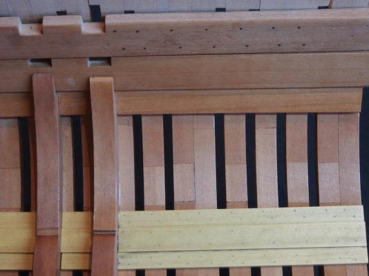
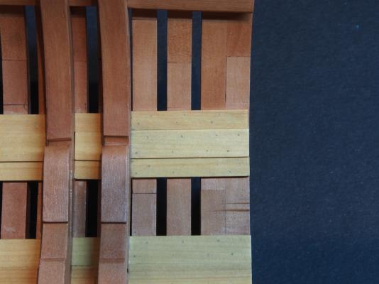
Mark's post suggests to me that perhaps there is plenty of room for "interpretation" here. So, I've gone ahead and prepared a test piece using a "spare" Mortar Pit Deck Clamp. This has used 0.5mm Copper Wire, using the template I showed earlier, then sanded back, blackened with LoS, and then one coat of Wipe-on Poly applied. I've just placed it on the model to get an idea of what it will look like in situ. In the picture, you can see the treenails in the planking below as a comparison. Pay no attention to the light coloured "dots" on the right hand end of the test piece - they were from earlier treenail tests. I think this is looking okay - not overdone. Grateful for any and all opinions/comments.
- 456 replies
-
- 11
-
-
- finished
- bomb ketch
- (and 2 more)
-
Thanks Mark, That actually IS quite helpful - it shows that either/any approach could be considered "correct".
- 456 replies
-
- 1
-
-
- finished
- bomb ketch
- (and 2 more)
-
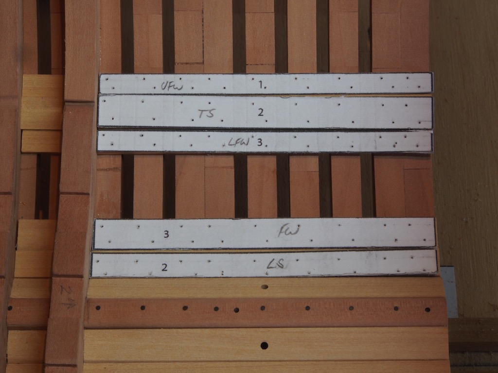
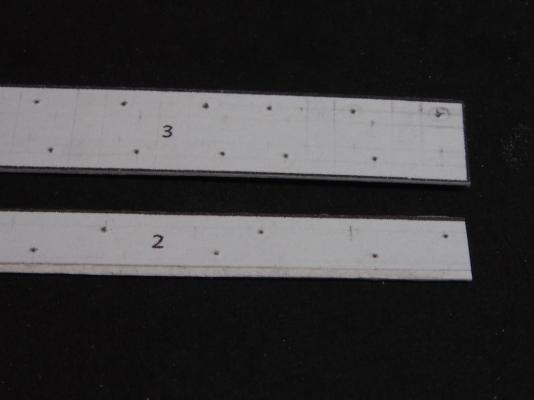
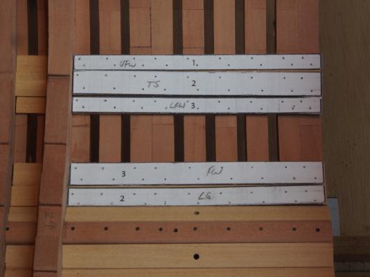
Thanks everyone for all the kind comments and the likes. I have a dilemma and am hoping that some of you knowledgeable folk can help me...... I had assumed that the Deck Clamps would be secured in place with a system of iron bolts. However, I can find no specific reference for this. I have checked through AOTS, TFFM and EdT's Naiad books and unless I'm reading right past it, I can't find a reference anywhere to guide me in this. Would they be bolted or treenailed? If bolted, what is the appropriate size? What bolting pattern would be used? What I've come up with so far, all assumption I might add, is that the bolts would be no more than 1" diameter (full size), which scales to about 0.5mm for this build. That "feels" about right, when compared to the 0.8mm bolts used in the frames and keelson. As far as patterns go, I am making an assumption that there would be at least one bolt in each frame, and two for the wider clamps. In this instance, the Mortar Pit Deck Clamp (Upper) is 24" wide (full size) and looks to be wide enough to have two bolts per frame, while it's partner (MPDC Lower) is 15" wide (full size) and looks about right for one bolt per frame, but in a staggered pattern. I've made up some templates for the bolting pattern described above. Before I commit to this, I'd love to hear any and all advice.
- 456 replies
-
- 3
-
-
- finished
- bomb ketch
- (and 2 more)
-
How about some TurboCAD help?
gjdale replied to jwileyr4's topic in CAD and 3D Modelling/Drafting Plans with Software
This article by our very own Wayne Kempson is a "must read" for anyone starting out lofting in CAD: http://modelshipworldforum.com/resources/plans_and_research/DraftingShipPlansInCADwayne.pdf I use TurboCAD (for Mac) and found Wayne's article a tremendous help, even though it's not TurboCAD-specific. The commands are all fairly common across software packages (I think). Wayne will also answer any specific questions you might have if you PM him. -
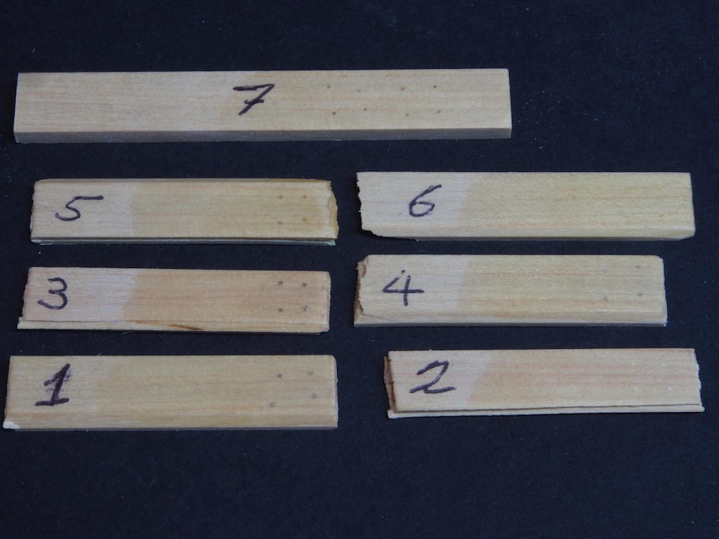
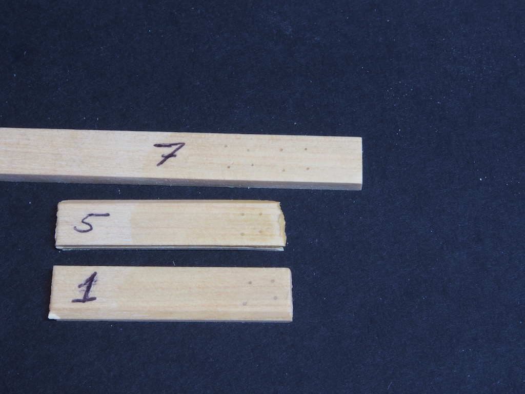
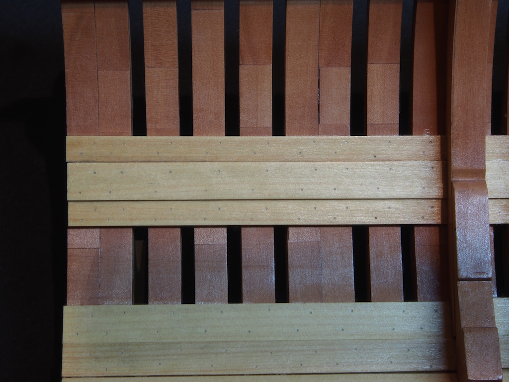
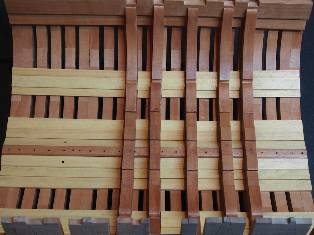
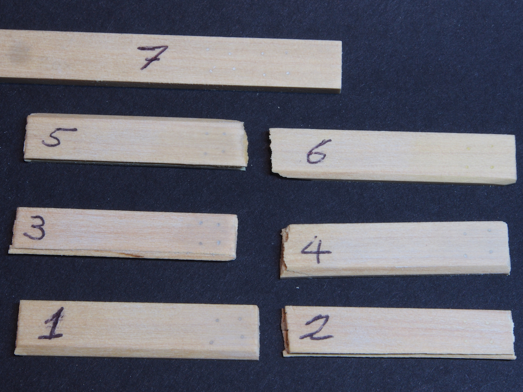
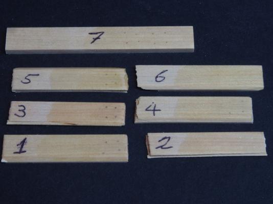
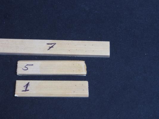
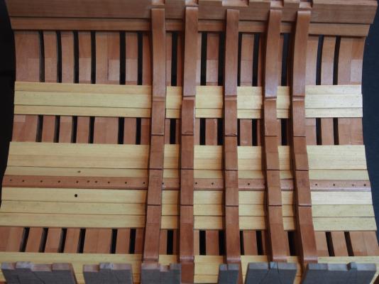
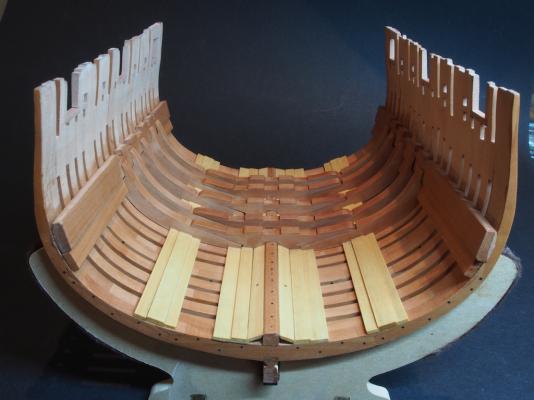
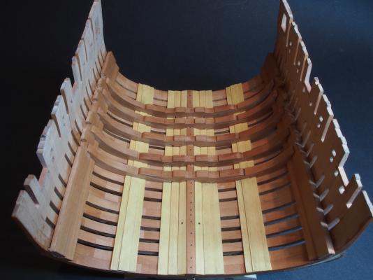
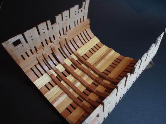
Thanks for all the input folks. The big tip was from both Mobbsie and Rusty, in actually applying Poly to the test pieces before deciding, so that's exactly what I did: The Admiral was consulted and immediately No.s 2, 4 & 6 were ruled out as being too light, and No. 3 for being too dark. That left No.s 1, 5 & 7: There was so little to distinguish between these three, that the choice came down to the method used. No.7 used Boxwood sawdust mixed with diluted PVA. No. 1 used a water-based wood filler, straight out of the jar. No. 5 was the same as No.1 but with a touch of Raw Sienna acrylic paint added. No.7 ran the risk of leaving a glue residue on the wood surface. No. 5 ran the risk of the paint staining the surrounding timber. No.1 offered no down side, so became the final choice by default. Cardboard templates were made up and drilled with a 0.4mm drill. The templates were temporarily fixed in place using double sided tape and the holes drilled. And here’s the resulting holes awaiting filler: Before filling the holes, the hull was removed from the jig and the exterior sanded fair. I cheated and used an electric “Mouse” sander for this. I was a bit worried about how the hull would stand up to this, but it was surprisingly solid. The Mouse made relatively short work of the fairing and did a very good job of it. I forgot to take photos of the exterior though! While I was at it, I made up a temporary work stand for the hull using the templates provided in the drawings (intended as the display stand). I just knocked this up using some scrap 6mm MDF and 6mm square stock for the stringers. I lined the inside with self adhesive felt to protect the hull while it is being worked on. The holes were then filled and the excess filler wiped off with a damp cloth. The whole of the interior up to and including the Mortar Pit Deck Clamps, was then given two coats of Wipe-On Poly (applied with a brush), with a light rub of steel wool between coats. The end result is faint, but distinguishable treenails - I'm quite pleased with how they turned out. In the following photo, you can see the temporary work stand: And finally, here’s a couple of overall shots of where she’s at now: Still tossing up about adding bolts to the Deck Clamps……….

- 456 replies
-
- 20
-
-
- finished
- bomb ketch
- (and 2 more)
-
Slow and monotonous they may have been John, but well worth the effort! They look great.
- 2,250 replies
-
- 2
-
-
- model shipways
- Charles W Morgan
- (and 1 more)
-
Hey Adam, Nice to see you back in the shipyard and posting again. Looking forward to the continuation of this lovely build.
-
Yep, the Optivisor is among the "essential" tools in my shop!
- 969 replies
-
- 1
-
-
- hahn
- oliver cromwell
- (and 1 more)
-
Thanks guys, Rusty has it right! I've just applied some poly and will re-photograph in the morning.
- 456 replies
-
- 1
-
-
- finished
- bomb ketch
- (and 2 more)
-
Hmmmmmmm.......... Interesting point you reveal about the changes in colour once the Poly is applied Mobbsie. Think I'm going to apply some Poly to my test pieces before deciding on filler colour. Yours looks fabulous with poly applied, by the way!
- 255 replies
-
- 5
-
-
- granado
- bomb ketch
- (and 2 more)
-
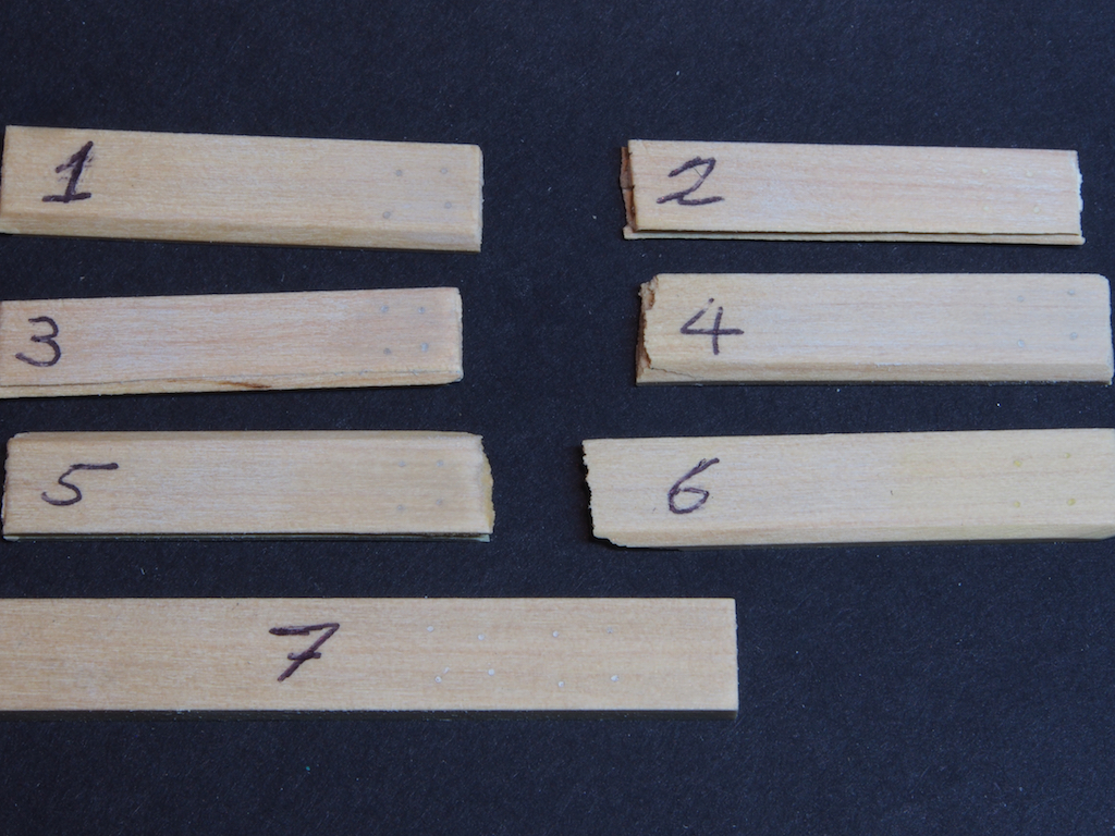
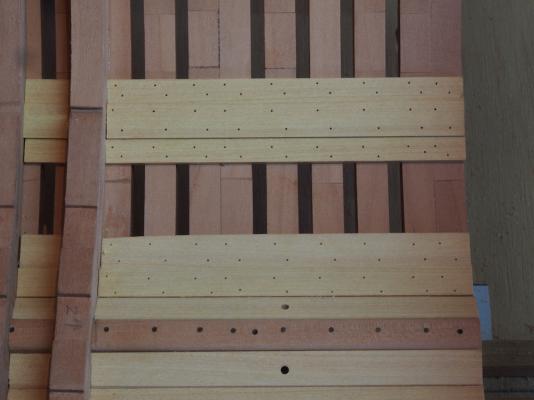
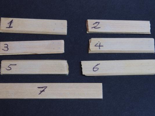
Hi all, Trying hard to keep up with Mobbsie, but this working for a living thing puts me at a distinct disadvantage! Have been doing some treenail tests using the "drill and fill" method and would appreciate some input as to what looks better. I won't say at this stage what the various concoctions used were as I'd like this to be a truly "blind taste test". Here's a couple of pics of the results. The only difference between the two is the placement of the test pieces in case camera angle made a difference. Voting lines are now open..........

- 456 replies
-
- 2
-
-
- finished
- bomb ketch
- (and 2 more)
-
Looking great Mobbsie. Must be a good feeling to successfully remove her from the jig. Looking forward to comparing notes on treenail concoctions.
- 255 replies
-
- 1
-
-
- granado
- bomb ketch
- (and 2 more)
-
Stunning Remco - just we would expect from you.
-
Great to see you back and posting again Bill. Just love drooling over your exquisite work!
-
Your work continues to amaze and delight me Alexandru!