gjdale
-
Posts
4,894 -
Joined
-
Last visited
Content Type
Profiles
Forums
Gallery
Events
Everything posted by gjdale
-
That's a neat innovation! It looks great.
-
 Okay Kevin, That's enough slacking off on other modelling projects for now. It's time to get back into the shipyard and get on with Miss Vicky.
- 1,319 replies
-
- 3
-

-
- caldercraft
- Victory
- (and 1 more)
-
Just got caught up on your log Per. Nice job. I look forward to seeing the rest of your journey from here.
-
Thanks Augie and Mark. Mark - apart from the limited amount of planking that has already been done on the inside, it will be fully planked internally above the upper deck (ie bulwarks etc).
- 456 replies
-
- 2
-
-
- finished
- bomb ketch
- (and 2 more)
-
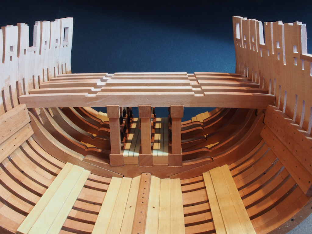
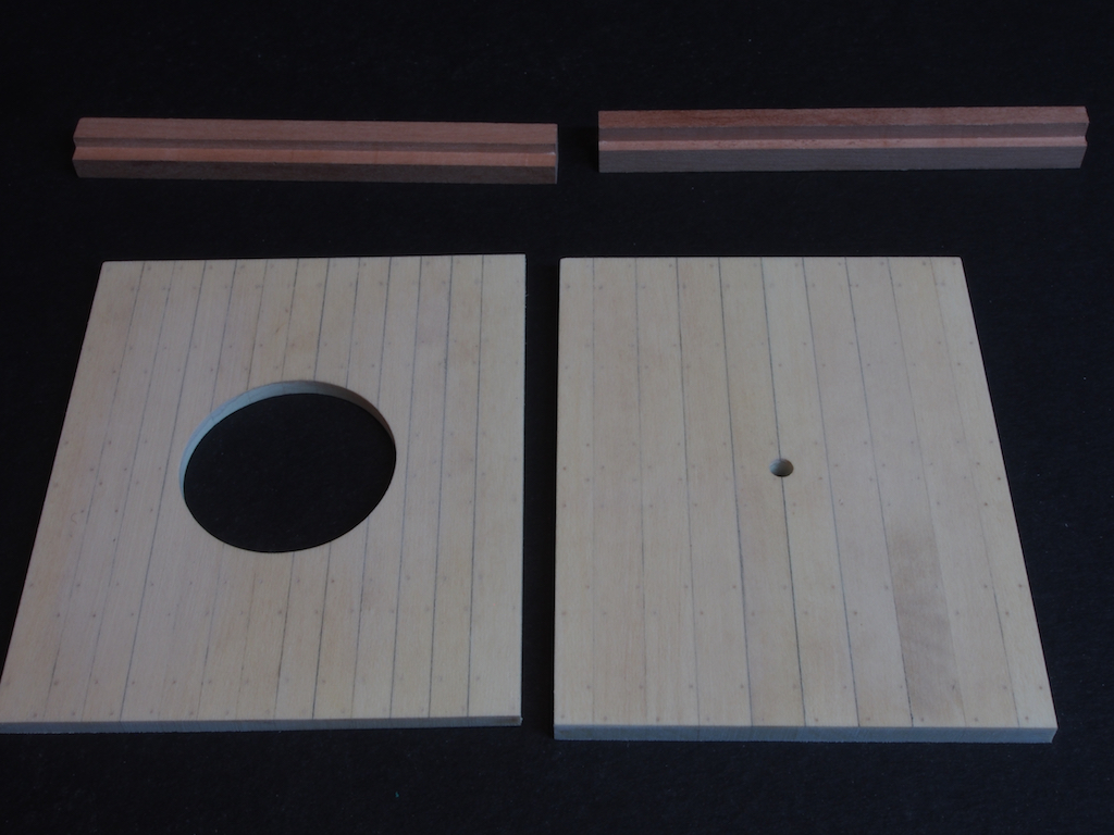
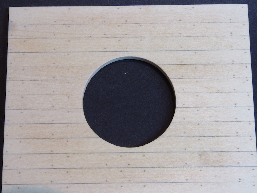
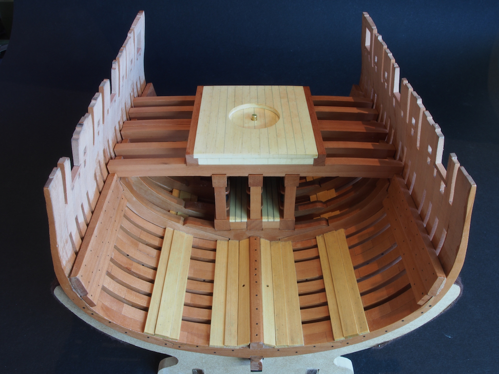
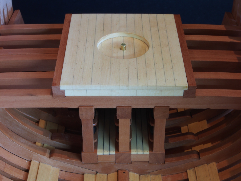
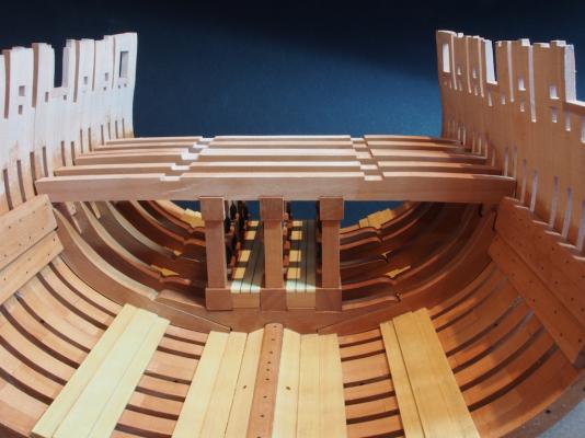
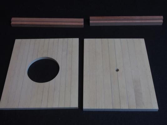
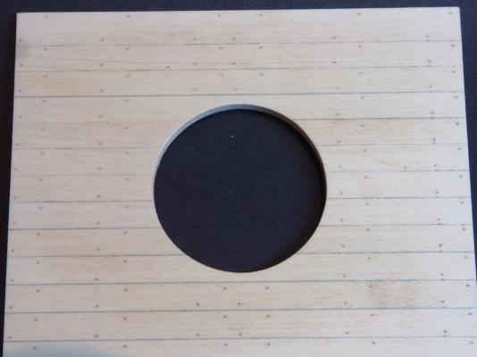
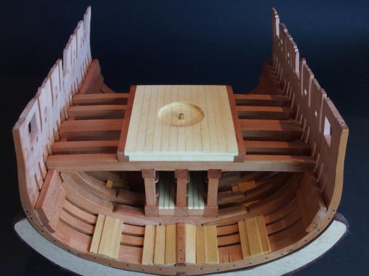
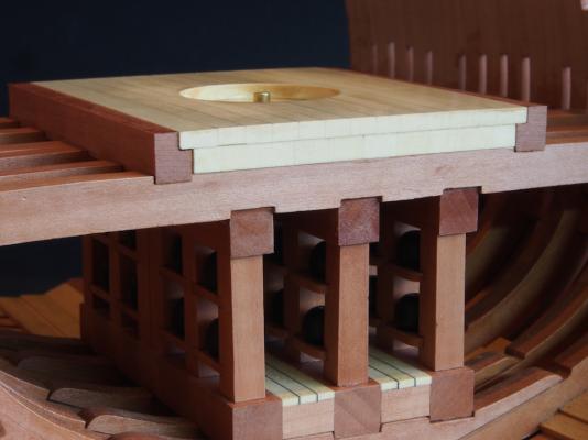
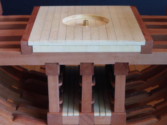
It's been a while since the last update. Recovery from my hip surgery has certainly slowed things down a little, but I have managed to make some progress. The next stage was construction of the Mortar Pit. Construction of the Mortar Pit Construction of the Mortar Pit commences with the six Mortar Pit Deck Beams that sit atop the Shell Room. These were cut from 1/4" Pear stock. Six rectangular blanks of identical size were cut and then spot glued together. A single paper pattern for the beams was then glued on to the gang of blanks and the notches for the Shell Room headers (5/16”) and the Mortar Pit Boundary Timbers (1/4”) were cut on the mill to take advantage of the still square faces. The round-up of the beams was then shaped using the spindle sander for the inside curve and the disc sander for the outside curve. After test fitting, the Deck Beams were used as additional support to ensure the Shell Room was squared up for final fixing. Once the Shell Room was securely fastened, the Beams were given a coat of Wipe-On Poly and glued in place. The Mortar Pit itself is fairly straightforward construction, consisting of two Boundary Timbers of 1/4” x 5/16” Pear, a Primary Layer of planking (3/16” Holly) and a Secondary Layer of planking (1/8” Holly). I decided to use pencil along the plank edges to simulate the caulking with these decks, rather than the black paper used on the deck of the Shell Room, partly because I was concerned about glue adhesion, and partly because I wanted to see what it looked like. Once again, the “drill and fill” method was used for simulating treenails. In retrospect, I should have sealed the Holly before applying the filler for the treenails as some of the filler has gotten into the grain of the deck and slightly discoloured it. Here are the component parts prior to receiving a couple of coats of Wipe-On Poly. The Primary planking has a 1/8” brass spigot inserted – this will locate the base of the turntable in a later stage of construction. The Secondary planking has a circular cut out for the turntable. This was formed by cutting roughly to shape on the Scroll saw, and then finishing on the spindle sander. Once both decks had been completed, it was a fairly simple case of finessing them to size to fit the space defined by the Boundary timbers. Here are a few pics of the completed Mortar Pit in place: Next up, fitting of the Upper Deck Clamps and preparation for construction of the Upper Deck. Stay tuned.....


- 456 replies
-
- 26
-
-
- finished
- bomb ketch
- (and 2 more)
-
Glad to hear you're feeling better and able to get back in the Shipyard Frank. Nice progress too.
-
Nice progress so far Jerry.
-
Wow - great job Ian! Those before and after shots really tell a story.
-
THE 74-GUN SHIP by Jeronimo
gjdale replied to Jeronimo's topic in - Build logs for subjects built 1751 - 1800
This is sure to be another outstanding build Karl. I'm looking forward to following your journey once again. -
WOW!!! That's looking just fantastic Mobbsie. Your scratch items are a real treat and the sails are well worth the pain they caused in the making. The colour looks great on them too.
- 62 replies
-
- 1
-
-
- harwich bawley
- fishing boat
- (and 2 more)
-
I've only just come across this log Dan, and have spent the last couple of days enjoying following your journey. Aside from being a top notch build, your log is also terrific as an instructional piece. Like many others, I have shied away from adding sails to my models to date. Seeing your approach though, may just change my mind for the future. Thanks for sharing so much of your knowledge and experience.
- 241 replies
-
- 1
-
-
- queen annes revenge
- pirate
- (and 2 more)
-
Nice paint job Ken. The use of clear to seal the edge of the tape to prevent bleeding is a great tip too.
- 440 replies
-
- 2
-
-
- niagara
- model shipways
- (and 1 more)
-
Nice to see you've arrived Mark - I was wondering who was going to cover the bar duties. Pass me a cold one please, to go with Sjors's popcorn.
- 1,306 replies
-
- 2
-
-
- syren
- model shipways
- (and 1 more)
-
A great display of both your engineering (drawing/design) and your machining skills Ian. That's a terrific result!
-
Sometimes it's nice to have a "side project" to keep the interest up when you reach a fairly monotonous stage in the main build. I'm sure you'll enjoy the Stage Coach Sjors - I think that is the same one that Adrieke built.
- 1,616 replies
-
- 2
-
-
- caldercraft
- agamemnon
- (and 1 more)
-
'Bout time you showed up with the popcorn Sjors!!! Sorry to hear that the medical situation is slowing you down Jesse. But as Augie said, we'll all be here ready and waiting for you when you're ready to go again. And now we have Sjors's popcorn to keep us going while we wait.
- 1,306 replies
-
- 10
-
-
- syren
- model shipways
- (and 1 more)
-
Ah! Just in time for a front row seat! Pass the popcorn please Augie.
- 1,306 replies
-
- 8
-
-
- syren
- model shipways
- (and 1 more)
-
Only just found your log MaryO, and you have completed the build. It looks like you did a great job on it and received plenty of helpful advice along the way. The end result looks fabulous and you can be very proud of your achievement. Well done! Best wishes for your next build. With your approach to learning and developing new skills as you go, I'm sure it will be equally enjoyable for you, and will achieve an equally good end result.
-
Looks like this will be an interesting build Jerry, and as you say, something a little different from the usual. I'll pull up chair and follow along too.