


AnobiumPunctatum
-
Posts
1,267 -
Joined
-
Last visited
Content Type
Profiles
Forums
Gallery
Events
Posts posted by AnobiumPunctatum
-
-
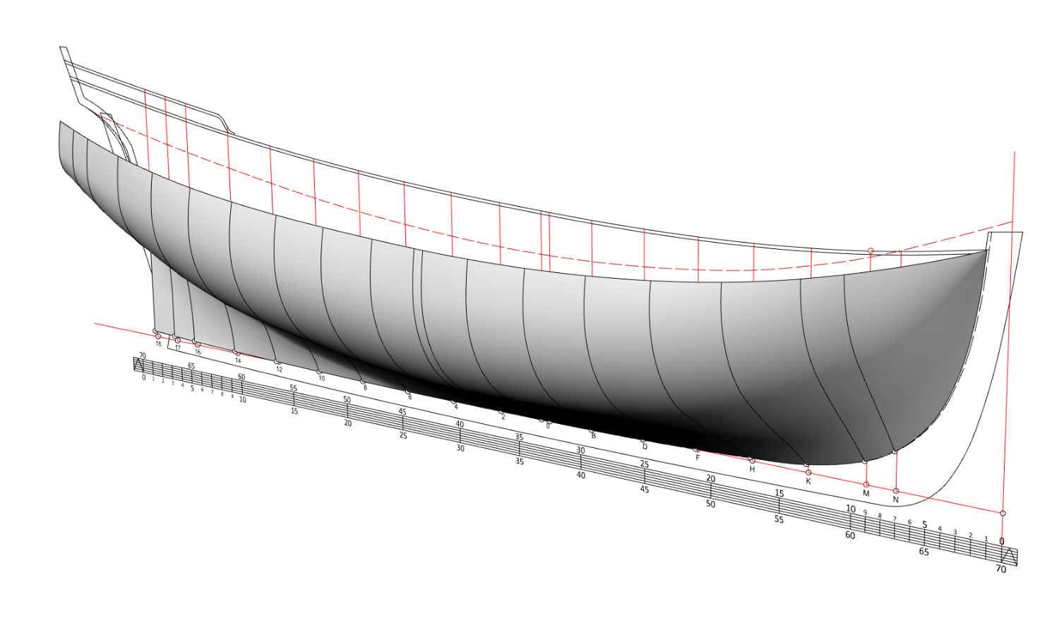
Yesterday I had the opportunity to watch the video of the online course. Afterwards I tried to represent a 2D reconstruction, which I have done in Autocad 2014, with Rhino. Enclosed is a screenshot of my first attempt. Next I have to extend the stern accordingly.
Many thanks to @Richard Dunn for his cursus, which was a big help for me to go my first steps with Rhino 7.

- Oldsalt1950, dvm27, Egilman and 2 others
-
 5
5
-
-
I have both woods in my stash. Boxwood is harder than yellow cedar. Bother timber you can combine with holy and a light colord pear.
I think it is a personal decision which timber you use. As Chuck has to have a look at the costs of the parts/model he offers, his choice is excellent.
I like to work with both timbers.
-
Chuck,
as I wrote earlier I wish you a lot of fun and success with the project. I took directly an abo to your build log.
I found inyour first post a very good idea, which helps me a lot by the design of a really old project of mine.
Thanks for sharing your idea and drawing.
- mtaylor, FrankWouts and dvm27
-
3
-
Absolut fantastic. Hoy do you paint the friezes? They look really realistic especially in the small scale
- billocrates and mtaylor
-
2
-
Congratulation for finishing this beautyful model.
-
-
-
-
-
They are looking much better than as your 3d model.
- Canute, mtaylor, chris watton and 2 others
-
5
-
-
Hi Chris,
will you offer your gun crew also in scale 1/48? The 3D model of them is looking great. I am really intersted in them. Further sailors and officers of the period of the American Wars of Revolution will be a nice add on.
- mtaylor, thibaultron, Dave_E and 1 other
-
4
-
-
Reallohn nice collection of ships equipment
- usedtosail, mtaylor, FriedClams and 1 other
-
4
-
-
-
This week I got a "little" parcel with really nice milled boxwood from hobymill.eu. Vahur put also some extra sheets and wood samples to my order.
The timber has real nice color and was excellent packed. Also the contact and information of Vahur was great.
Hobbymill gets from me ⭐⭐⭐⭐⭐ of five possible. Highly recommended
-
Thank's very much. Let's answer your questions:
2 hours ago, druxey said:Nice start! Will you be milling templates for every frame?
In the moment, this is my plan but I don't know if I will change this with more experience in frame building. The advantage of the method are the different levels, which make the build much easier.
1 hour ago, allanyed said:Are you gluing up the frames while in the jig, and if you are, any problems arising with the frame being glued into the jig and having problems getting it out?
By the testframe I did not have any problems, to get the frame out. I don't need much glue during the build. You can also use a colophane foil or a thin layer of clear varnish to avoid problems.
QuoteAre you using a CNC mill?
Yes, I got one last year. The idea is a first result of my learning curve. I have a lot of other ideas, but for these I have to learn 3D construction. All my drawings are in the moment in 2D and for Triton I will not change this.
-
The last two years I needed my workshop as homeoffice. I started building Cheerful at the dining table, but this was also not a good idea. Now I am back in my office which gives me the possibility to use my workshop as shipyard again.
To practice I build a test frame from an old piece of wood.
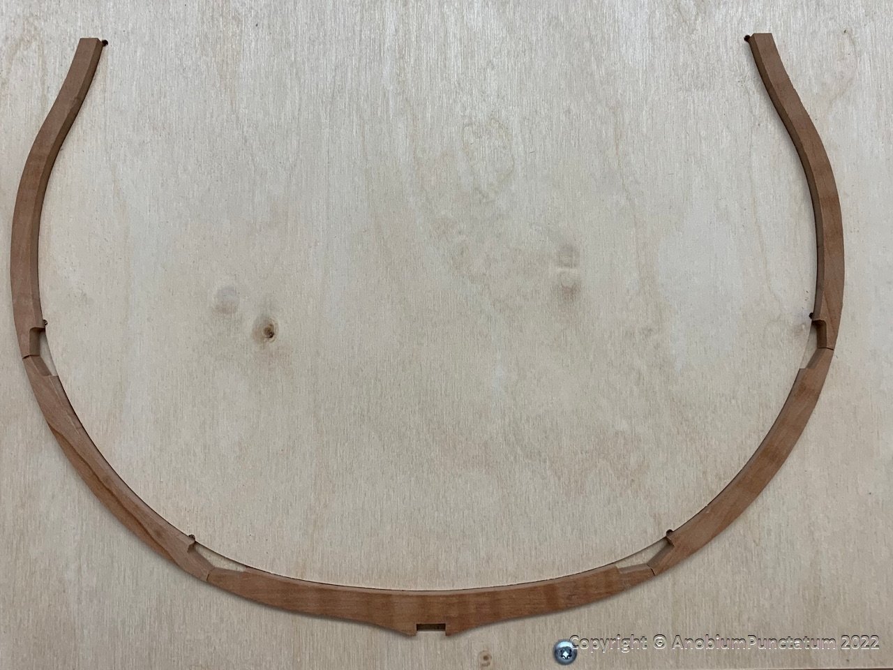
Instead of a paper base, I milled a template from plywood, which already takes into account the different thicknesses of the futtocks.
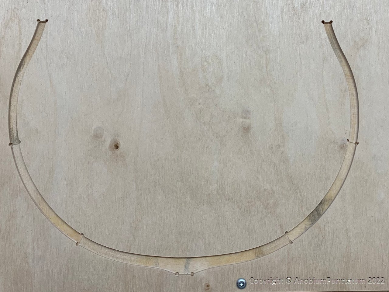
On this template, the futtocks were first glued together and then the chocks were added.
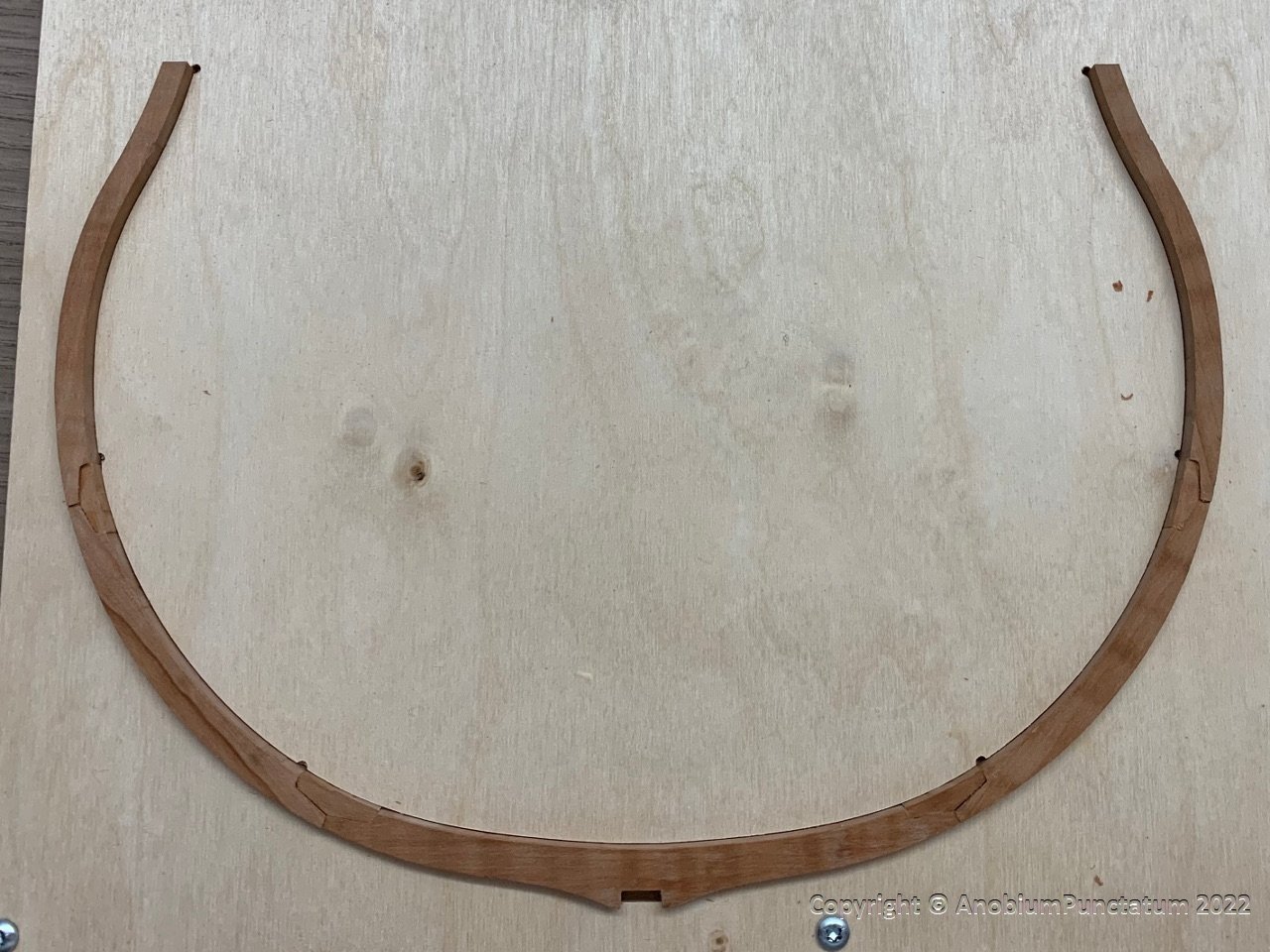
Finally a photo of the finished test-frame.
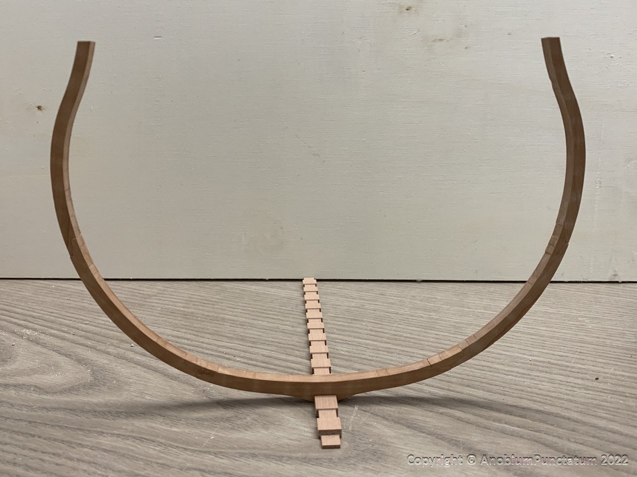
Now I can start with the serial production.
-
Wonderful progress. It's really nice to see, that people give this old group project a try or continue their build.
- Gabek, shipcarpenter and mtaylor
-
3
-
-
Congrats for finishing this wonderful model.
- Louie da fly, mtaylor and Keith Black
-
3
-

Sloop Speedwell 1752 by Chuck - Ketch Rigged Sloop - POF - prototype build
in - Build logs for subjects built 1751 - 1800
Posted
This is a really interesting way to build the deadwoods, which I have not seen before.