BANYAN
-
Posts
5,962 -
Joined
-
Last visited
Content Type
Profiles
Forums
Gallery
Events
Everything posted by BANYAN
-
 Geez I would like to see that model in real life, it looks great by camera so to the eye it would be stunning. Nicely done Jason cheers Pat
 -
Thanks for taking the time to explain and share the dimensions of your jigs Ed, very much appreciated. Now that I understand the principle it all makes sense and shows the experience you bring with your ideas. Your YA books are on my Christmas list I have recently trawled your Naiad volumes again, and find the information and practical advice relevant to all model building, kit bashing as well as scratch building any model, very helpful. The Masting and Rigging volume of YA will be particularly valuable as most reference books, except for David Antscherl's Vol 4 of TFFM, only address the principles of these disciplines ;whereas, your effort is written with a more practical aspect of "how to". As YA is more relevant to my era of interest, I will find this log and your forthcoming volume very helpful. cheers Pat
- 3,618 replies
-
- 5
-

-
- young america
- clipper
- (and 1 more)
-
Hi Ed, many thanks for your photos of the jigs and YA; she is looking stunning in that shot and I know you still have a lot of rigging detail to add. I am a 'little thick' when it comes to visualising some things and having difficulty in understanding your comment about the centre line screw at the top, in the top jig, so that a curved spar will lie flat? I thought that laying them in the V groove would hold them, what is the purpose of creating the curve then straightening it with a wedge? I am sure there is a reason otherwise you would not have done it. I have assumed the curve was in the lateral dimension, but you may mean the longitudinal dimension? If the latter, does that mean the bottom end of the bed sits on the base and forms an expanding gap into which you drive the wedge at an appropriate point to cause a bend such the tip of the rounded spar sits at the bottom of the groove (for support while working it)? Could you also, if it is not giving too much away (from your forthcoming book) provide the dimensions of your cams? I understand that different shapes/sizes may be needed for different stock but this would be a good starting point (and I admit my self-interest here as I am also working 1:72) cheers Pat
- 3,618 replies
-
- 3
-
-
- young america
- clipper
- (and 1 more)
-
Some really nice detail you have achieved on those turrets Danny. cheers Pat
- 295 replies
-
- 2
-
-
- amatsukaze
- halinski
- (and 2 more)
-
Quite the lady of the sea now Russ with all her skirts on, she only needs the 'ruffles' to look the complete part very nice lines to this model. cheers Pat
- 420 replies
-
- 2
-
-
- captain roy
- lugger
- (and 2 more)
-
Hi Pete, I have read a discussion in either Underhill (Masting and Rigging the Clipper Ship and Ocean Transport), or Kipping (Rudimentary Treatise on Masting), about the shape of the bowsprit in which there is a discussion that some bowsprits had a flattened upper / topside and some had blocks (steps) to assist access along the bowsprit. These were supplemented by the use of manropes with the outboard end secured to the Cap and the inboard at two vertical stanchions at the head timbers/knightheads. I can't recall which at the moment and I am up to my ears in research for Victoria; but, i will have to return to rigging in coming months. If I come across the actual reference I will post the detail of where to find it.It is relevant for me also as HMCSS Victoria had the manropes (specified in the Contract and shown in lithographs), and in some visual evidence I have, may also have had the flattened topside of the bowsprit. cheers Pat
-
A tad of filler and a lick of paint will fix it but I don't see too much amiss there Russ. Did you have the lens cranked to max zoom when looking? cheers Pat
- 420 replies
-
- 3
-
-
- captain roy
- lugger
- (and 2 more)
-
Hi Ed, very nice work as usual and a great level of detail for such a scale. Enjoying this. cheers Pat
- 3,618 replies
-
- 2
-
-
- young america
- clipper
- (and 1 more)
-
Better not forget anything before gluing Greg, it would be kinda hard to place items in some of those spaces. Seriously nice detailing. Look forward to seeing it painted. cheers Pat
-
HMCSS Victoria 1855 by BANYAN - 1:72
BANYAN replied to BANYAN's topic in - Build logs for subjects built 1851 - 1900
Hi folks, I have nothing but conundrums at the moment I need to resolve quite a few small issues/details before I can progress the build. First up: In the Victoria Contract it states: "To have three pairs of towing timbers on each side, as shown in the drawing, of Africa oak, secured in the usual way, each timber having an iron cap over it with a pin through the head." Earlier, I made the decision/assumption that these probably refer to the bollards of which there are three pair. The following extract, taken from of a woodcut (The London illustrated News - The launch of the Victoria) shows one pair of these, but this would have been prior to them having been finished with the cap and pins. So, what does that actually mean? The following shows four possible interpretations. A trawl of my references and the internet has not helped me resolve which way to go. My leaning at the moment is option B which would be a square iron cap over (not just a plate on top as shown at A) with a pin through each timber not both as shown at D. C is a full length cap using the timber as the inner structure. Also, I believe the square/rectangular shape would have been retained with perhaps a slight chamfer on each corner in the central part of the body vertically? Suggestions most welcomed; and an image would be even better (circa mid 19th century). The second issue: Warping blocks - again the Contract states: "… Gallows, bitts and cross pieces, warping blocks on each bow and quarter with scores in them." A search has failed to elicit sufficient detail to allow me to position them nor what they would look like. The only reference I have found at the moment is in The Elements and Practice of Rigging And Seamanship, Volume 1, by David Steel (1794) - a section on Blocks has a plate which amongst many others shows a warping block. Shown below. Howeever, according to Falconer these were used for taking warps in ropemaking or the like. I have looked through several seamanship references including Dana, Nares and Martelli but no decent explanation as to what they are used for or how they are fitted. The bit about "with scores in them" throws me off as this could suggest they may not have been blocks at all? I also do not think these were timber heads as they would have been called that? I am starting to think that perhaps they may be some type of fairlead used to warp the ship etc. the score could perhaps be an opening in the top to let in the rope? Again any help most gratefully received. cheers Pat- 1,020 replies
-
- 5
-
-
- gun dispatch vessel
- victoria
- (and 2 more)
-
Terrific detail and very neat rigging Ed. cheers Pat
- 3,618 replies
-
- 5
-
-
- young america
- clipper
- (and 1 more)
-
Looks very effective Ed, I like the idea of the loosely twisted wire. The smallest copper chain I have found so far is 42 lpi so this tip is very handy. cheers Pat
- 3,618 replies
-
- 2
-
-
- young america
- clipper
- (and 1 more)
-
Nice rigging effort Dave; a simple but very effective jig for doing the detail. cheers Pat
-
Hi guys, I concur with Druxey's observation - I have read in an Ordnance Handbook, or 'official' publication about ordnance being manufactured back in the mid-1800s - just cannot recall the publication at the moment (may have been Douglas but would need to check). The author states that these barrel markings were only applied to naval style guns used in coastal defence. In this publication there is also some discussion about the use of Dispart and Tangent sights (introduced by Miller for naval guns) so may have been in relation to the fact that such marks were unnecessary given these sights (this my interpretation as there is no clear relationship implied nor discussed in the book). If the factory/ordnance authority publish such a statement it is good enough for me Even with such sights, the lock issue as Jud describes was the major problem. This lead to the introduction of the gunlocks at about the same time, or just a little later. cheers Pat
-
Hi Sailor and Dave, Dave, sorry to intrude on your build but in relation to Compressors Vs Stoppers: My understanding is the compressor is near or part of the naval pipe (where cable leaves the deck, usually near the capstan down/up from the cable lockers below); the cable stopper looks a little similar but functions differently and is located closer to the hawse pipes? cheers Pat
- 742 replies
-
- 5
-
-
- constitution
- frigate
- (and 1 more)
-
HMCSS Victoria 1855 by BANYAN - 1:72
BANYAN replied to BANYAN's topic in - Build logs for subjects built 1851 - 1900
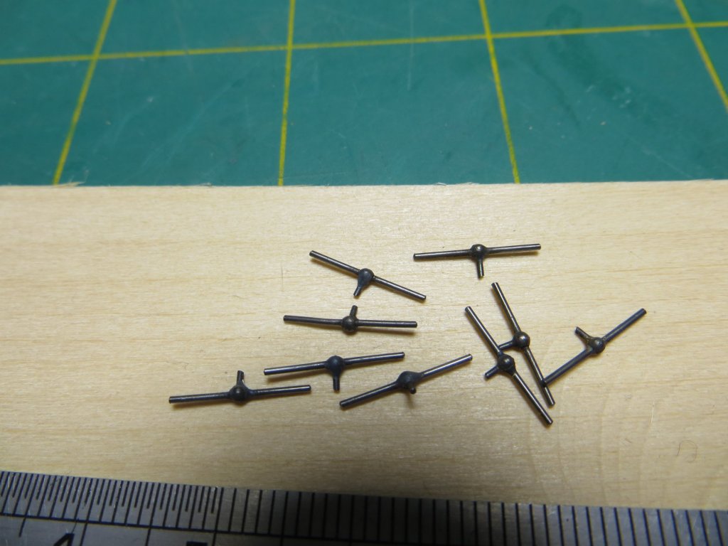
Thanks Russ and Carl. The bulbous 'nails' are an aftermarket ring bolt I picked up from a Melbourne Hobby Store. No maker's name etc on them so I can't help you there sorry. The ball parts are straight sided with a rounded top/bottom - the spherical shape (by adding to the sides) I imparted with solder. cheers Pat- 1,020 replies
-
- 5
-
-
- gun dispatch vessel
- victoria
- (and 2 more)
-
HMCSS Victoria 1855 by BANYAN - 1:72
BANYAN replied to BANYAN's topic in - Build logs for subjects built 1851 - 1900
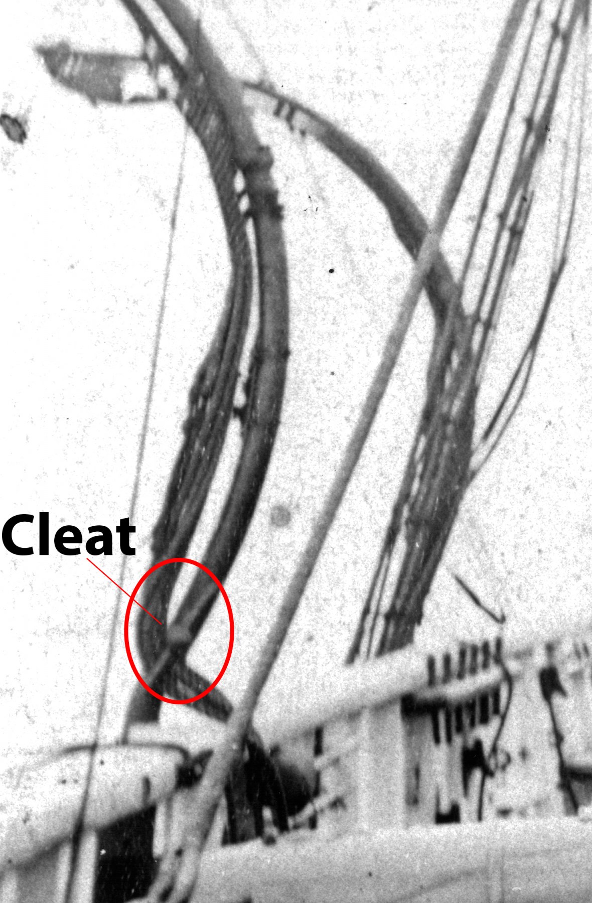
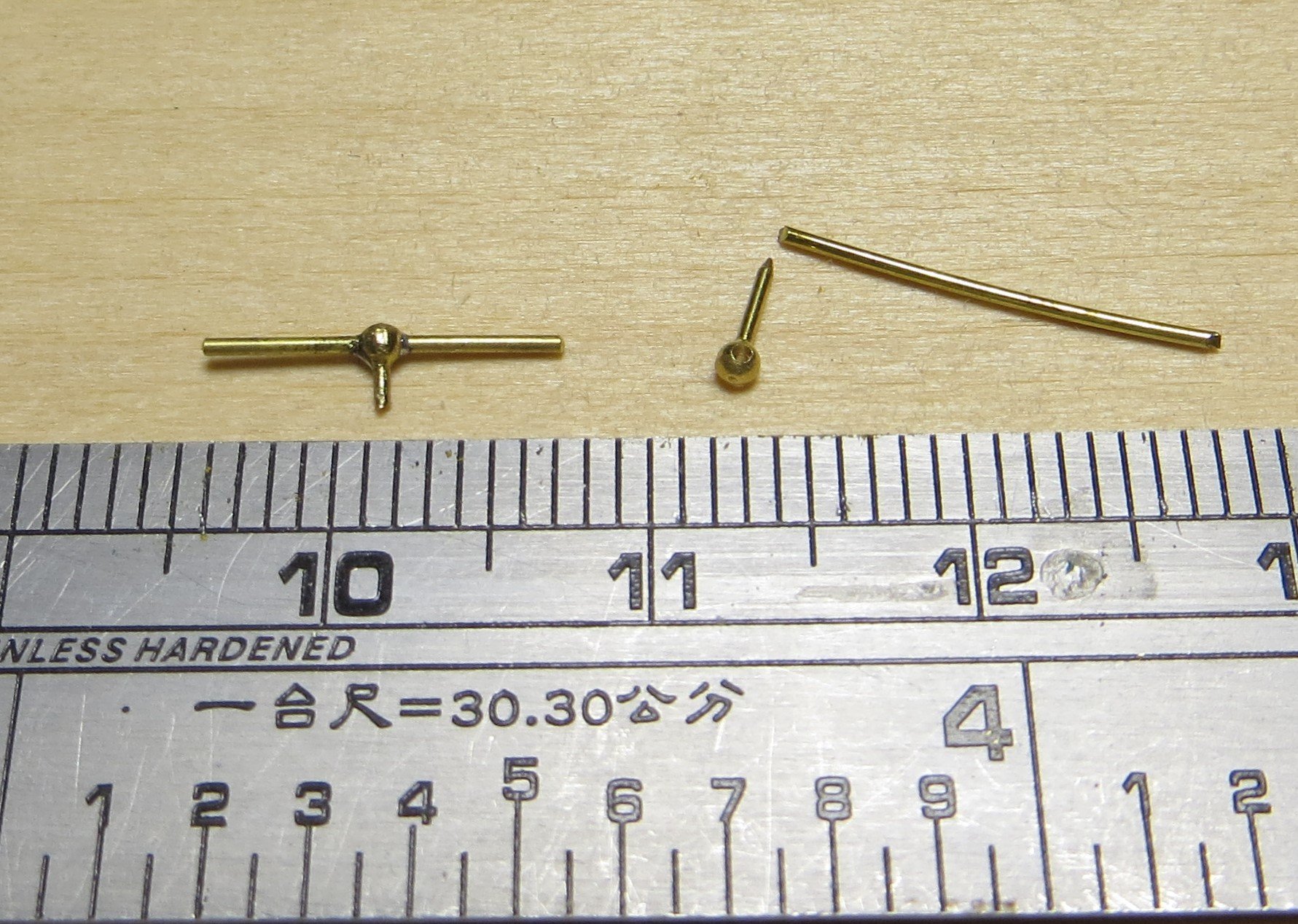
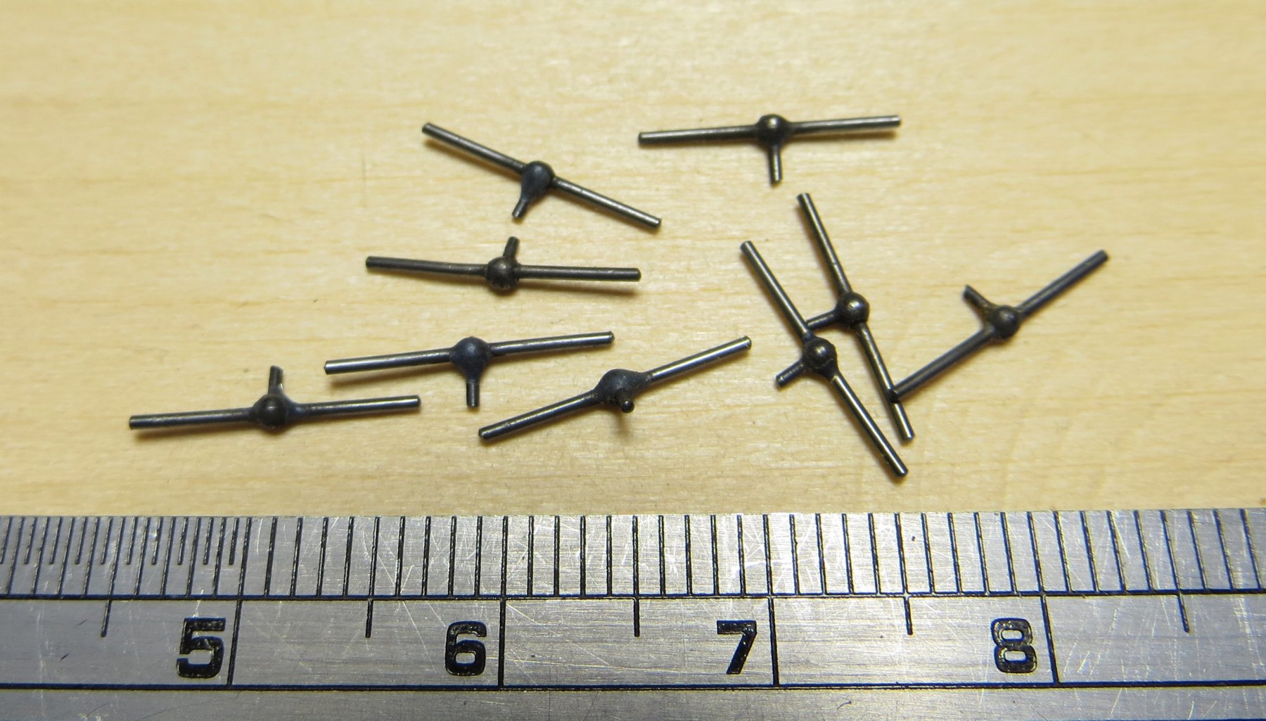
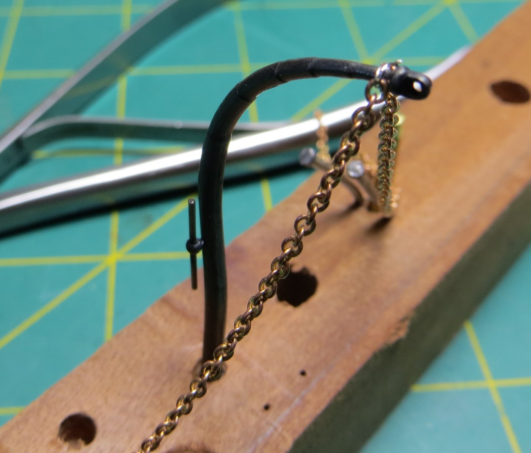
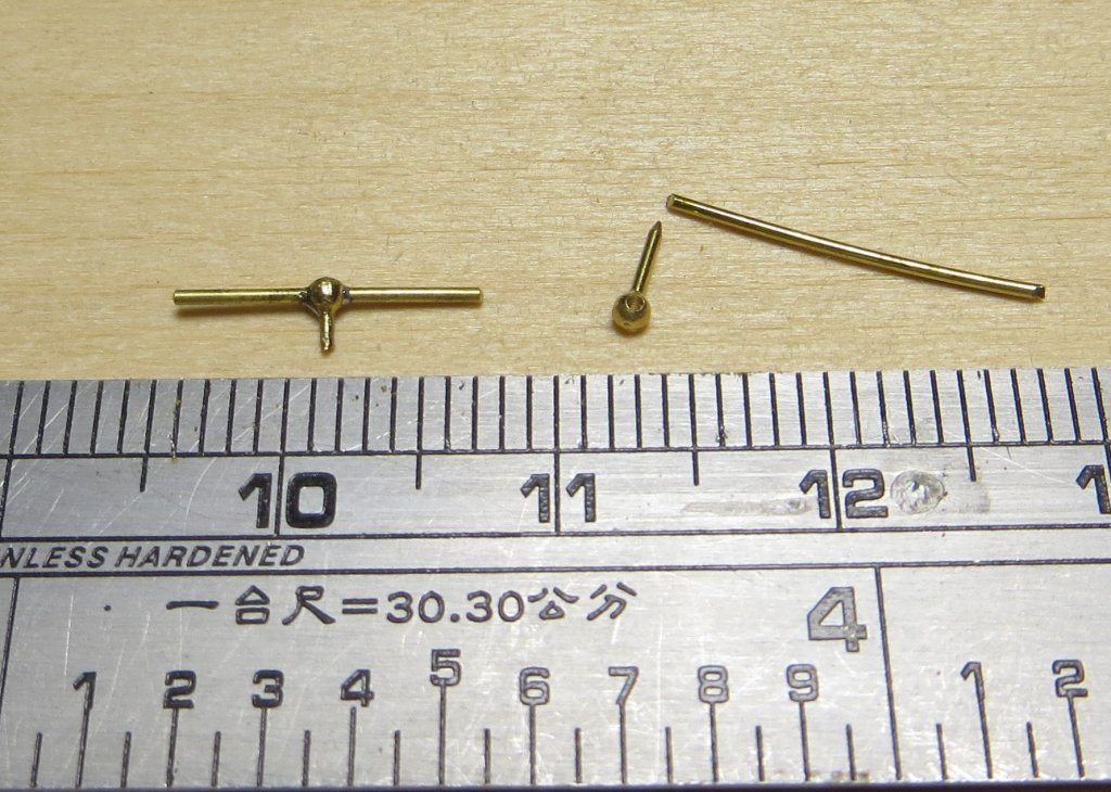
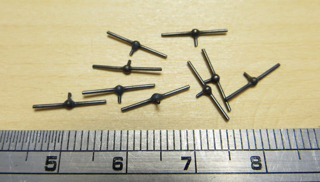
i all, I have been experimenting to see how to complete the davits I discussed earlier. The picture I have of the Officers and some crew on quarterdeck, shows te davits in the background. Note the shape of the davit cleat. I decided not to go with the modified shroud cleats and made some new cleats for which I have shown some of the process below. The cleats have still to be polished to remove some more of the oxidation but I think they have come up OK? One is shown loosly fitted (not glued yet) on a davit arm along with an experiment for fitting the stay and brace chains to the davit head. this was done with some very fine nichrome wire which I think will do; just need to work out how to fix it in place now Note the chain is too much out of scale but is the smallest I have now (12 links per inch) I think I need about 24 links per inch to get the scale right.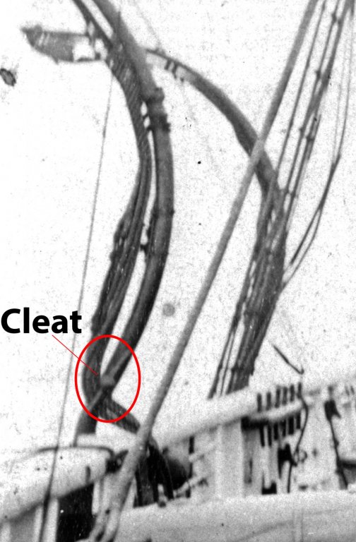

- 1,020 replies
-
- 12
-
-
- gun dispatch vessel
- victoria
- (and 2 more)
-
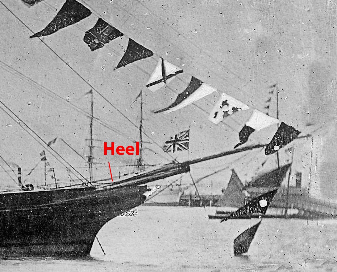
Seriously nice work Ed, as Rob states the idea of the plate through the martingale is a great tip. Rob, my Victoria (1855) also has the heel finishing in approximately this position, but I think in my case there is a heel chock at the base. The following is a much cropped extract from a photo of the ship I have and although grainy seems to confirm this - but open to interpretation. According to Underhill, this chock could extend back to the stem, or finish short (ramping/slanting backwards to the bow. cheers Pat

- 3,618 replies
-
- 5
-
-
- young america
- clipper
- (and 1 more)
-
Coming along very nicely Danny; if you hadn't pointed out the shorter arms due to initial misplacement, i for one would not have noticed cheers Pat
- 295 replies
-
- 4
-
-
- amatsukaze
- halinski
- (and 2 more)