


BANYAN
-
Posts
5,852 -
Joined
-
Last visited
Content Type
Profiles
Forums
Gallery
Events
Everything posted by BANYAN
-

A Lorch Micro-Mill that never was ...
BANYAN replied to wefalck's topic in Modeling tools and Workshop Equipment
Another tantalising update Eberhardt - I have stocked up on the tissues so ready for the main installments That knurling tool does a great job. cheers Pat -
Thanks Mark and Frankie; much appreciate your responses. I have rechecked the AOTS (by Marquardt also) and again all that is said is "belays at Top" - so I think I will go with that - saves me a bit of rigging also . Frankie, that is a good solution; I will see if I can achieve that as it is a bit fiddle to reach in there but I should be able to do it. Many thanks again Pat
-
Thanks again to all the likes and comments; the encouragement sure helps with big decisions like this. Popeye, I won't tell anyone about the sheet lines if you don't . Thanks for the comment re the finish, but the photos hide some of it - they really do need a "cut and polish"; especially close to the iron work as evidenced in photo 4. cheers Pat
- 517 replies
-
- 3
-

-
- Endeavour
- Artesania Latina
- (and 1 more)
-
Great job on the Catheads mate. Where did you get the crowns? I have not been able to find anything of the right scale size yet. cheers Pat
-
I have fitted the reefing tackles to the foremast topsail yard, but am having difficulty determining how the running part (hauling part) of the tackle is belayed for HM Bark Endeavour as of 1768/1770. According to the AOTS, there is a simple statement (callout number with comment) that it is belayed at the associated Top. The running rigging belay plan does not show the belay point. Earlier diagrams for the Top indicate two eyebolts in the after part of the Top (located just aft of the lubbershole) on either side of the mast. However, from what I can determine these are for the Topgallant Tye tackle? Can anyone point me in the right direction please. Peterson is too early to use as a reference and I cannot find anything in Lees (yet). cheers Pat
-
Nice work Greg, all that detail will really enhance the build. cheers Pat
- 342 replies
-
- 5
-
-
- dreadnought
- zvezda
- (and 2 more)
-
Nice work on the roughtree rails Dashi; I wish I had researched them a bit more as I have a step rather than the straight run. cheers Pat
-
Nice work Piet, a very clean cut indeed. ....and great to see you wearing the safety glove cheers Pat
-
Great work as usual Glenn, I had to look closely at a couple of the photos as you could believe you were looking at the actual paddle-steamer. cheers Pat
-
Great detail and excellent control of the scroll saw to achieve it Gaetan. cheers Pat
- 728 replies
-
- 2
-
-
- le fleuron
- 64 gun
- (and 1 more)
-
Looking good Greg, that wooden deck really brings her to life. Hope you don't have to do too much more corrective action with the CA. cheers Pat
- 342 replies
-
- 5
-
-
- dreadnought
- zvezda
- (and 2 more)
-
Thanks for looking in and the comments folks; much appreciated. Yep Mark, first wood ship model apart from the battle station I built along the way as practice There are heaps of little errors from the days I first started but these I can live with. cheers pat
- 517 replies
-
- 4
-
-
- Endeavour
- Artesania Latina
- (and 1 more)
-
Nice jig Mark, very effective. With such light passes i don't think you will have to worry about wear on the sanding drum causing spacing issues. cheers Pat
-
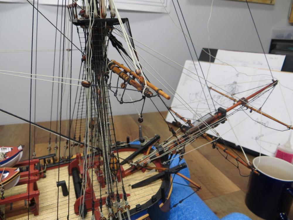
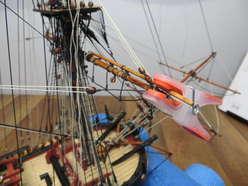
Part 2 - sorry some of the photos are not that well focused in the earlier post. In the following you can see the new solder joints, and the finished results for the port side also. Unfortunately it was impossible to get any shots of the actual soldering operations. Photo 4 (first in this post) shows the third-hand setup which was raised by using solid wood blocks, photo 4 shows the new soldered joints (mid-yard and end-cap are visible (before cleanup and repaint) and photo 5 shows the port side boom completed. cheers Pat
- 517 replies
-
- 13
-
-
- Endeavour
- Artesania Latina
- (and 1 more)
-
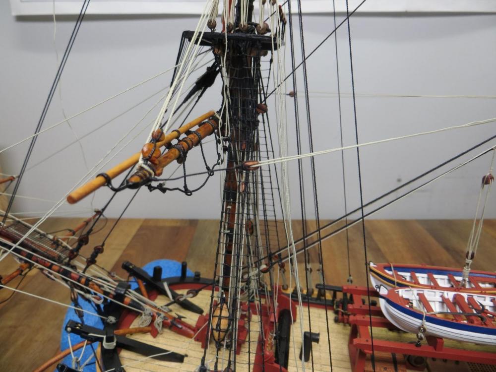
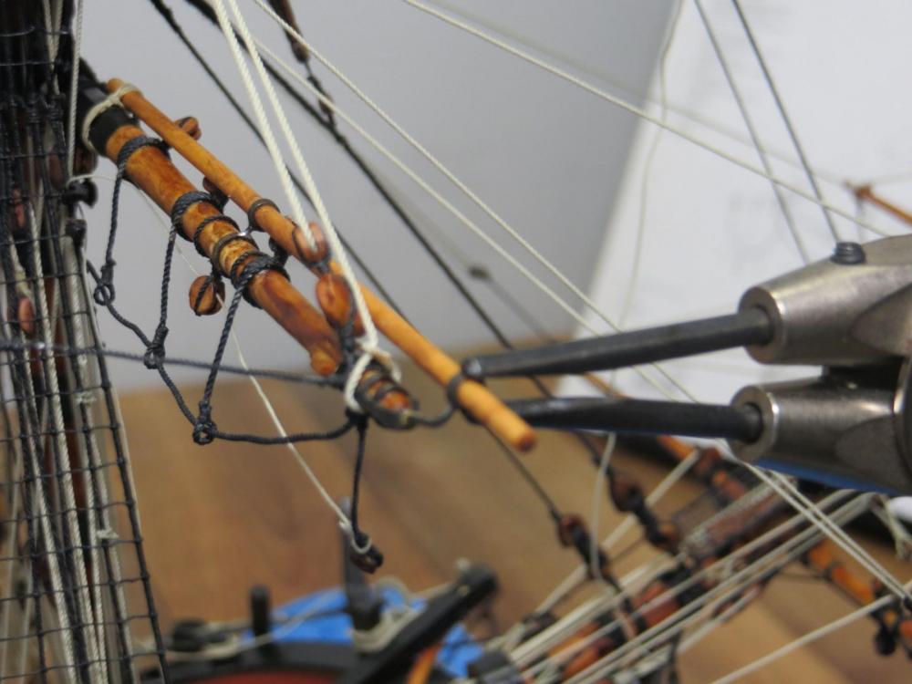
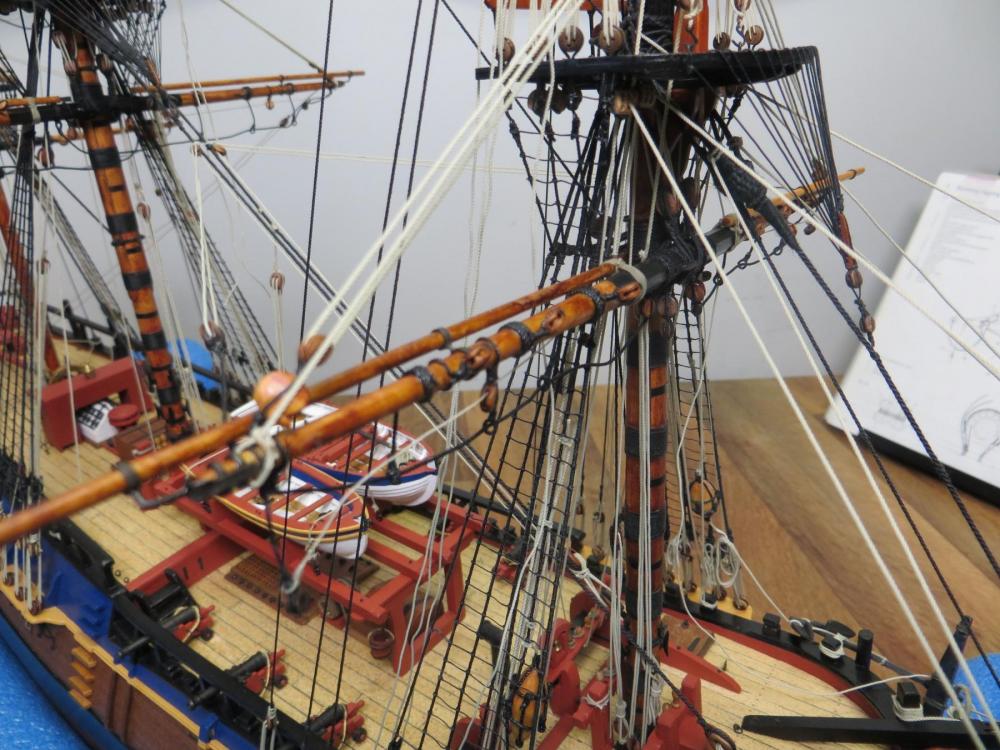
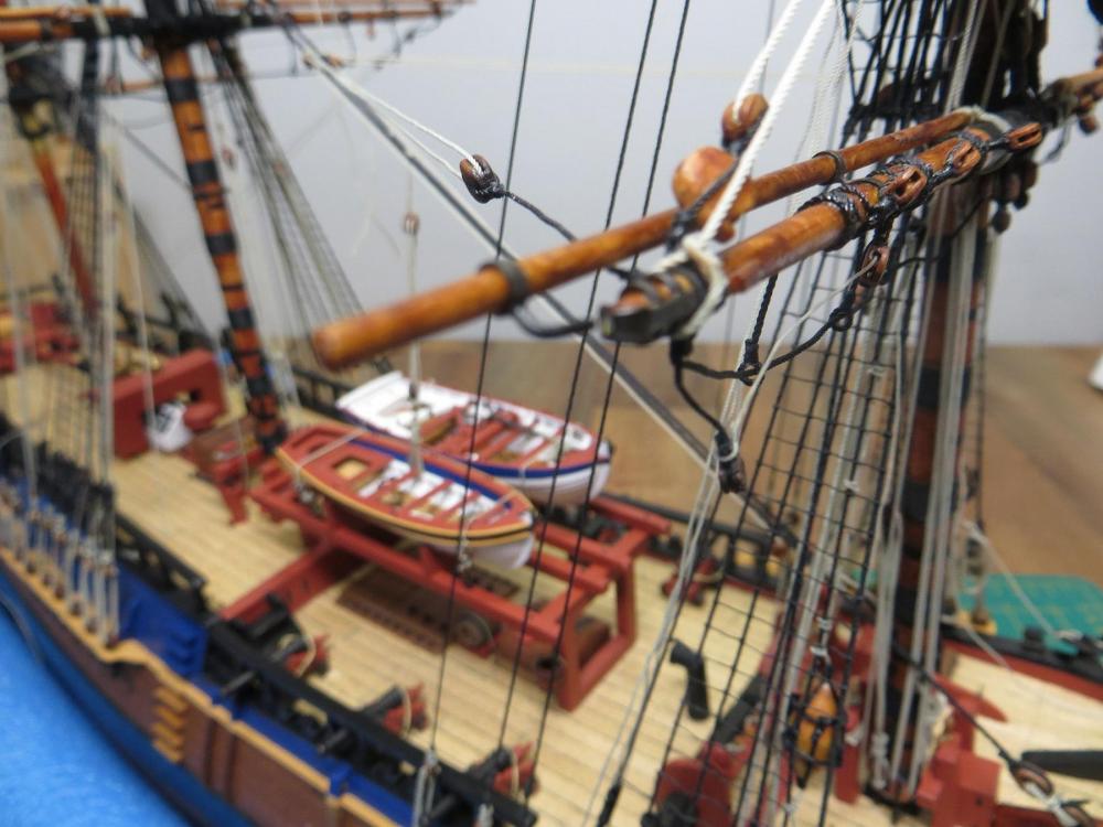
Hi again folks. Well I just couldn't live with the incorrect location of the studding sail booms (aft of the yard rather than forward as shown in photo 1), so I attempted to fix the location of the studding booms on the fore lower yard. I decided the best way was to try and fix it in-situ, as completely unrigging it would have been problematic. This brought about another complication in that it would be impossible to lash/bend the inboard ends of the boom as they were very close to the mast and quite difficult to get at. Having experimented a little, I found the best way was to actually use thin CA on the inboard lashings to hold them in shape. I then used a little acetone to weaken the bond on the yard. I am not sure what the long term effects of this process will be on the scale rope, but I am hopeful. This was the only way I could find to ensure the lashing held its shape while I rotated them. I decided to cut/snip the end cap iron and was then able to slide the studding boom out, but unfortunately, not without braking the solder joints on the mid-yard arm irons. As you can see from the photos, the lashings held their shape very well when I rotated them forward. I then rotated the mid-yard arm iron forward also, rest the studding boom and held it in place with a soft peg while I resoldered the the mid-yard arm joints. I then used a third hand (from GRS) to hold the end iron in place and resoldered them also. This process was only possible due to using a resistance soldering unit which gave me total control over the placement and level of heat. Overall a satisfactory result, but I will need to clean-up and stain the yards again as the acetone wrecked the finish - this was unavoidable but an acceptable result. The part one photos show the start of the process, through to the reinstall of the boom. The same process was carried out for both sides. Photo 1 shows the incorrectly positioned studding sail boom; photo 2 shows the end cap iron cut ready for the removal process (sorry a little out of focus); and photo 3 shows the repositioned boom held temporarily in place for soldering the mid-yard iron. cheers Pat
- 517 replies
-
- 12
-
-
- Endeavour
- Artesania Latina
- (and 1 more)
-
Very nice Druxey, she looks like she is floating in the air. cheers Pat
- 641 replies
-
- 7
-
-
- greenwich hospital
- barge
- (and 1 more)
-
Your efforts have paid of Cristi, those decorations look really good. cheers Pat
-
Looking really good Jason. Yep agree with your interpretation of British naval practice for the aft to forward direction, but according to my info, the plates overlapped by 1.5" on the upper and after edges. This method/system resulted with the overlap of the plates on the trailing end/edge (much like fish scales as suggested above). The purpose for the upper edge overlap is so that when the ship ploughed down into a wave there would be less resistance on the leading edge of the plate (less pressure in the vertical dimension = less chance of separation). cheers Pat
-
Looking good Dave. I used .25mm on mine as it wrapped around the ring better. cheers Pat
-
A belated happy Birthday "young" fella I hope you had a wonderful day (and spoiled rotten). Oh, and the railings and rooftop look very grand; a great fit! cheers Pat
-
Incredible detail at that scale mate; you'll be trying out with a grain of rice before long cheers Pat
-
That's a bit of a 'rum' (odd) deal on the Admiralty paint Glenn; a bit greedy of them packaging it like you say. I could get it (well I haven't tried for a while) as individual bottles no problems her, but not worth you effort as the postage from here would kill off any savings even if you did go with it. The Ronan flake white looks good though and the lighter coating (wash) helps show the details very well. cheers Pat


