BANYAN
-
Posts
5,851 -
Joined
-
Last visited
Content Type
Profiles
Forums
Gallery
Events
Everything posted by BANYAN
-
 Alan, asto the oversized hole, was there a leather puddening/strip in the 'bed' to protect the timbers? cheers Pat
 -
Steven, try SpotLight or similar store for some fine 'tulle' - amazing how fine you can get. Sorry to hijack Greg. cheers Pat
-
Certainly looking good Rob; she is really starting to show her character now cheers Pat
- 1,208 replies
-
- 3
-

-
- great republic
- clipper
- (and 1 more)
-
Ditto; looks like just the setup for some quality modelling time. cheers Pat
- 943 replies
-
- 3
-
-
- hahn
- oliver cromwell
- (and 1 more)
-
Up to your usual very high standards of quality materials and workmanship Chuck; nifty idea of the binder clips and 'L' brackets (I'll stow that idea away for future use ) cheers Pat
- 1,784 replies
-
- 4
-
-
- winchelsea
- Syren Ship Model Company
- (and 1 more)
-
Nice work, and useful technique cheers Pat
-
That is one very hard-worked ship Greg. Your weathering techniques at scale show you have a lot of talent (and patience) n this field. A very good looking model of a working-ship mate. cheers Pat
-
As always your very crip, clean joinery is an inspiration cheers Pat
-
HMCSS Victoria 1855 by BANYAN - 1:72
BANYAN replied to BANYAN's topic in - Build logs for subjects built 1851 - 1900
Thanks Ed and Rob, very much appreciate the comments and encouragement. I have a ways to go yet to achieve the same level of quality you guys produce, but learning with every 'mini-project' cheers Pat- 993 replies
-
- 2
-
-
- gun dispatch vessel
- victoria
- (and 2 more)
-
Very nice joinery for that wheel mate; I think you would have given the old masters a run for their money. cheers Pat
-
Nice work on the rigging Dave; very tidy indeed. I will also need to try and get hold of some of that timber it looks great and will be nice along side one of my other faves "Tasmanian Myrtle" Enjoy the shore leave mate, but don't follow that band too closely (they simply faded away after showing so much promise.) cheers Pat
-
Some nice improvements there Martes. I must admit I am a 'sucker' for good graphics in these styles of games to maintain my interest. A realistic algorithm or two to control ship behaviour and damage inflicted/received are the other two main priorities. cheers Pat
-
HMCSS Victoria 1855 by BANYAN - 1:72
BANYAN replied to BANYAN's topic in - Build logs for subjects built 1851 - 1900
Thanks Michael, much appreciated cheers Pat- 993 replies
-
- 2
-
-
- gun dispatch vessel
- victoria
- (and 2 more)
-
Looks good Steven; hopefully all continues going well with this redo. The carvings look smoother than before with the pear wood. cheers Pat
-
HMCSS Victoria 1855 by BANYAN - 1:72
BANYAN replied to BANYAN's topic in - Build logs for subjects built 1851 - 1900
Thank you very much for the encouragement and comments gentlemen; much appreciated. cheers Pat- 993 replies
-
- 3
-
-
- gun dispatch vessel
- victoria
- (and 2 more)
-
Many thanks Vossie, you seem to have a good 'handle' on all things tools (for ship modelling) You're right about the GRS prices (even on eBay - that is ridiculous) cheers Pat
- 714 replies
-
- 2
-
-
- lady nelson
- victory models
- (and 1 more)
-
Nice work Martes and thanks for sharing Martes. What are your plans for these? Are you going to make them available as add-ons? You appear to have put a lot of work into these. cheers Pat
-
Adapting DRO Devices To Shop Tools
BANYAN replied to Thistle17's topic in Modeling tools and Workshop Equipment
Thanks for sharing Joe, I will be interested in your final comments as I have been 'dabbling' with more 'manually controlled' methods of repeatability (all too complicated for my liking to date). cheers Pat -
HMCSS Victoria 1855 by BANYAN - 1:72
BANYAN replied to BANYAN's topic in - Build logs for subjects built 1851 - 1900
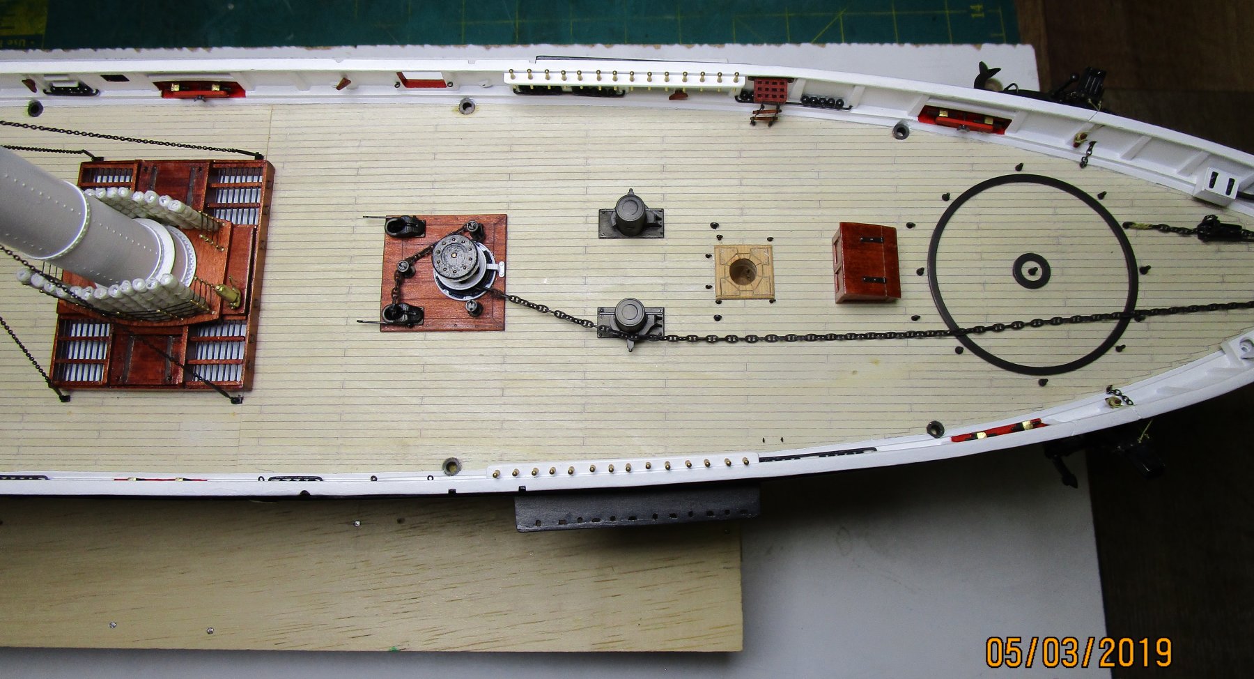
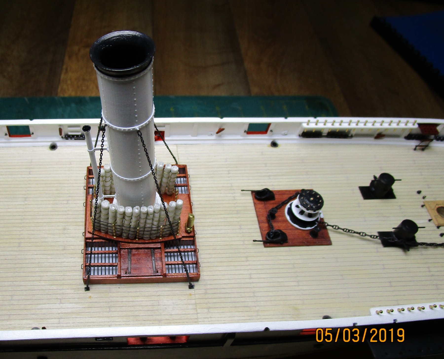
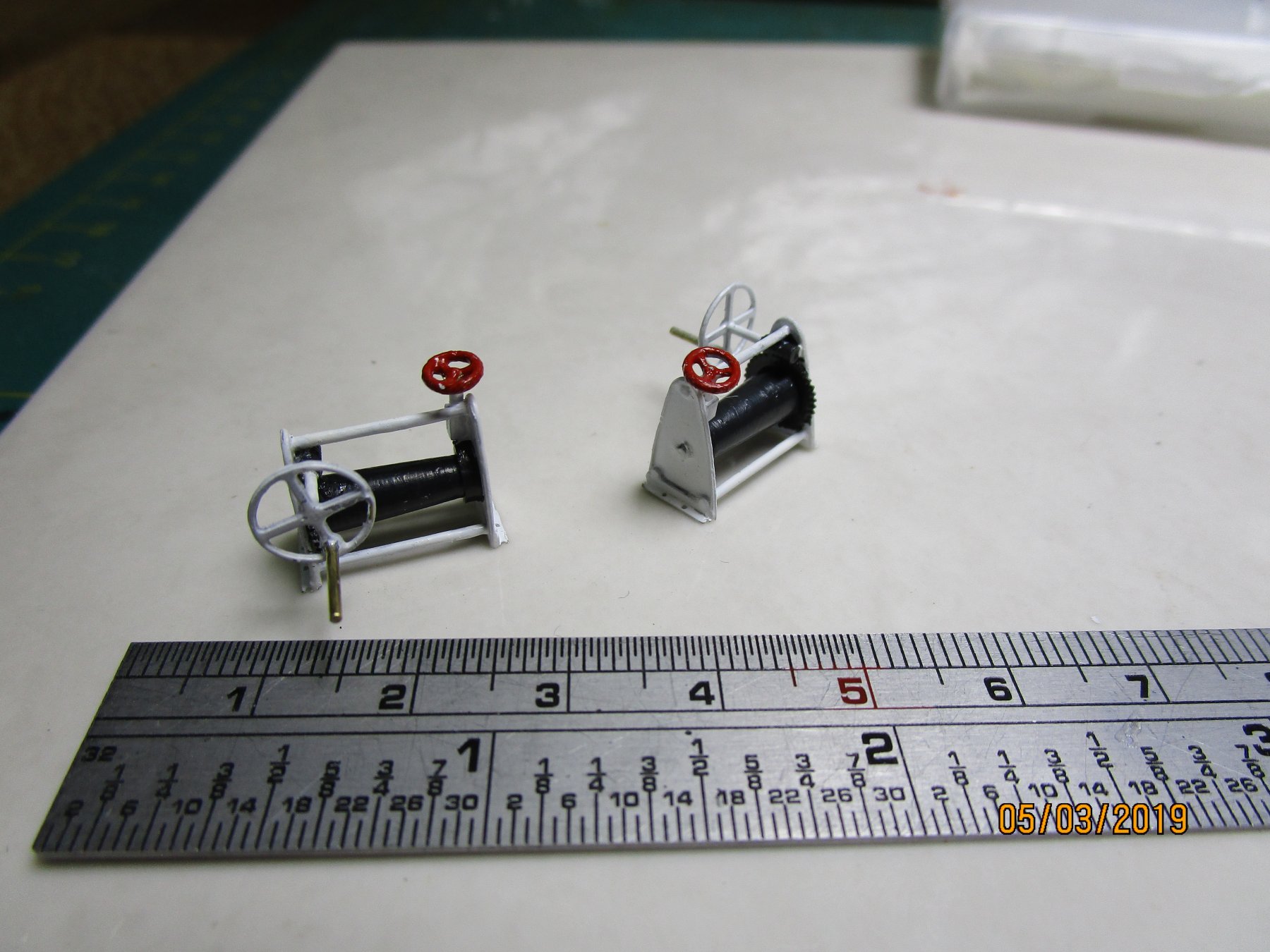
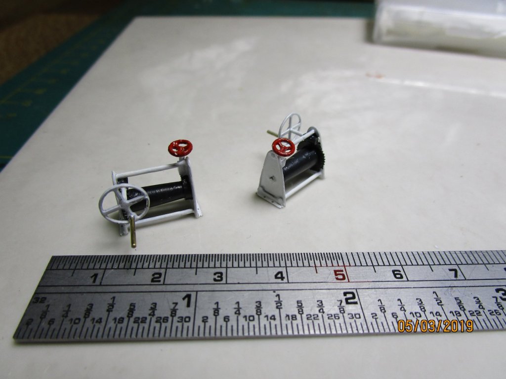
Thanks Dave; appreciate your comments. Some further small updates; I think the photos show all. First is the completed (minus firehose/rack) of the Downton Pump area; then the foredeck with chain blackened, and the funnel with its stay chains and finally the painted purchase winches. cheers Pat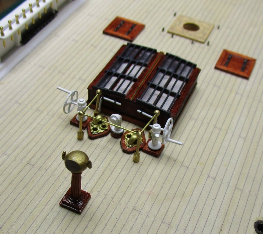


- 993 replies
-
- 21
-
-
- gun dispatch vessel
- victoria
- (and 2 more)
-
That looks pretty good Steven; as you say at this scale it is very acceptable. cheers Pat
- 740 replies
-
- 1
-
-
- Tudor
- restoration
- (and 4 more)
-
I am glad to hear I am not the only one Keith - I find that having just become proficient with a tool, jig or technique, I then put that aside until the next model by which time I have to relearn a lot of it again. I am envious of those who can master these things and simply step back into the process without issues. BTW I like the stops, mic adjuster etc fitted to your Byrnes saw, have you covered these in another forum as I would be interested in learning more about them. cheers Pat
-
Nice adaption using the vise Vossie. What brand and model is the vise? (sorry if you mentioned this earlier) cheers Pat
- 714 replies
-
- 2
-
-
- lady nelson
- victory models
- (and 1 more)
-
As with everything you do Gaetan, you strive for the highest standard you can achieve; your dedication certainly shows in the quality of your models (and photography) - impressive. cheers Pat
-
Very nice work Greg, you are showing some excellent detail (and talent) with this model. Those nets must have severely restricted ship's speed when deployed? cheers Pat