


Charter33
-
Posts
415 -
Joined
-
Last visited
Content Type
Profiles
Forums
Gallery
Events
Posts posted by Charter33
-
-
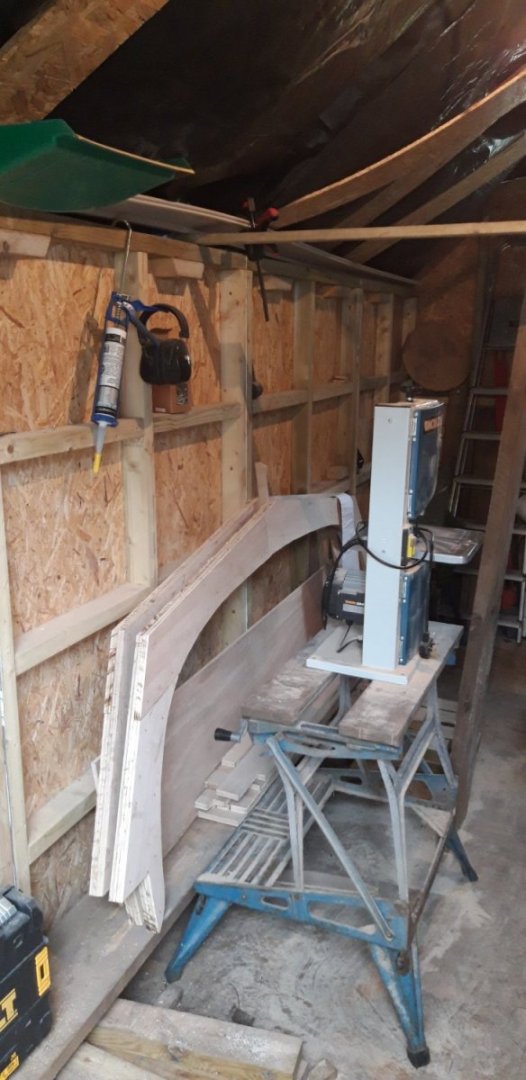
New blade arrived and I also took the opportunity to carry out some maintenance on the blade guides, the thrust bearing behind the blade in particular had seen better days.
Spent the afternoon making the knees that will help fix the roof frames in place using some of the pine boards that were previously shuttering for the concrete base.
Big day tomorrow ... weather promises to be dry, frames all sanded, other commitments cleared, so it's finally time to erect the roof structure ..... fingers crossed!
- Jack12477, Javlin, GrandpaPhil and 5 others
-
 8
8
-
It's all coming together very nicely David. Impressive to put it mildly!
-
Looking good Ron. I found this stage very satisfying as progress was quite quick through all the fore deck fittings. Lots of interesting little challenges..... have fun!😄
-
-
After a break to clear the Admiral's extensive project list, which apparently take precedent over a humble work space, the six roof frames are now complete apart from a final sanding.
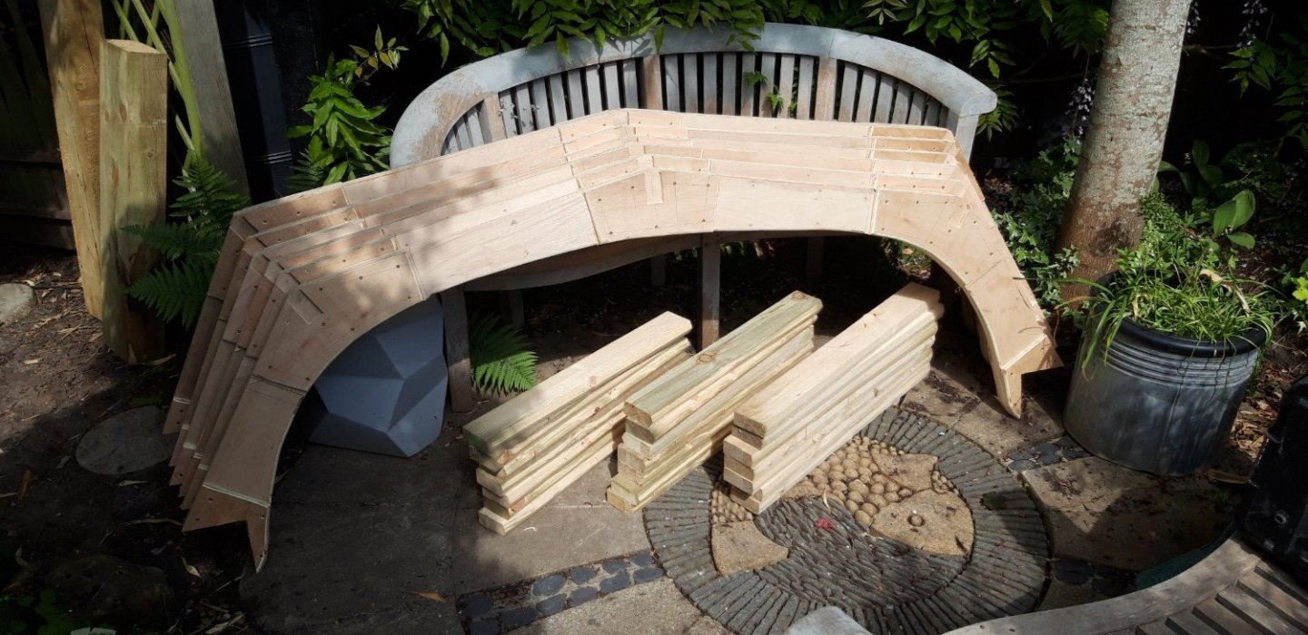
The ply reenforcing pieces glued and screwed to the corners have been modified to take the spacing beams. These beams have been machined to profile and are made from treated pine off-cuts from a flight of sleeper based garden steps built last year. The ends have been widened and extended following Ron's suggestions. I was hoping to cut pairs of knees to go either side of each end to fix the frames to the top of the wall panels but was scuppered by the bandsaw blade snapping. New blade due to arrive at the end of the week......
Cheers,
Graham.
- Ras Ambrioso, thibaultron, Egilman and 7 others
-
10
-
Birchwood Casey solution can be a bit tricky at times! Over doing the soaking time was an issue I struggled with initially. A couple of strategies I found helped:
- a short dunk agitating the components in the solution, rinse, repeat if necessary.
- slightly dilute the solution.
With those particular eyes I strung batches of them on a loop of cotton thread and treated them.
Good luck! 🤞
-
Looking very good, Ron. 👏
Have you thought about using a brass blacking solution on those copper eyes?
-
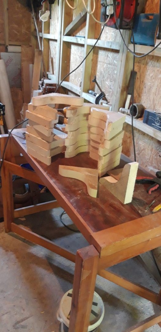
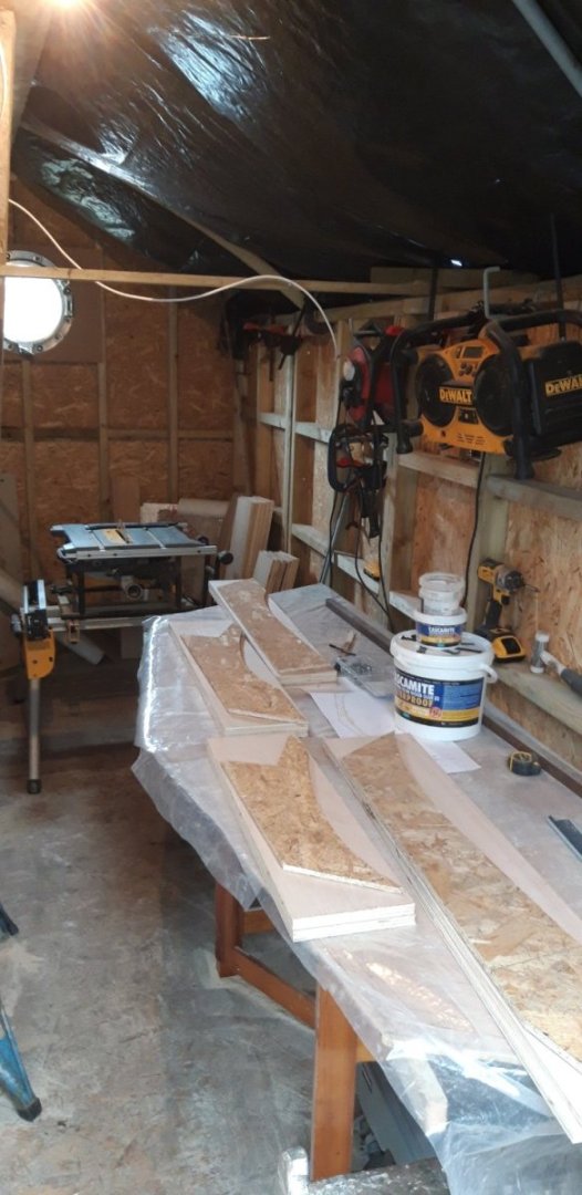
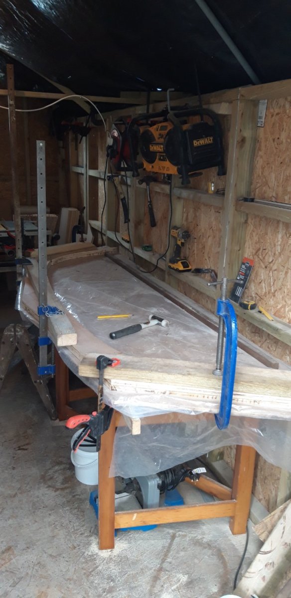
Please excuse the mess, but I've been busy!
The roof truss building board, complete with all six variants laid out in preparation, has been set up as a workbench.
The addition of a temporary light over it helped......
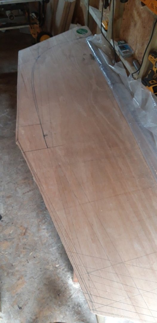
I've made a set of templates to mark out the four main parts for each truss
Once roughly cut to shape these are adjusted to suit one of the profiles.
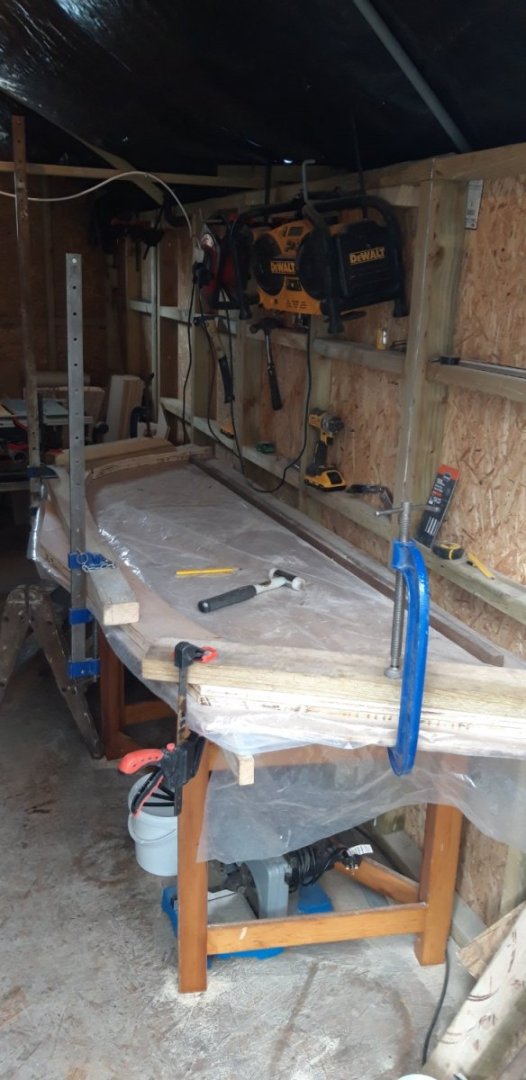
and then the assembly is glued, nailed and clamped.
Three down, three to go.....
When all have been completed the building board will be cut up to make the plates that reenforce the corners and ends.
Cheers,
Graham
-
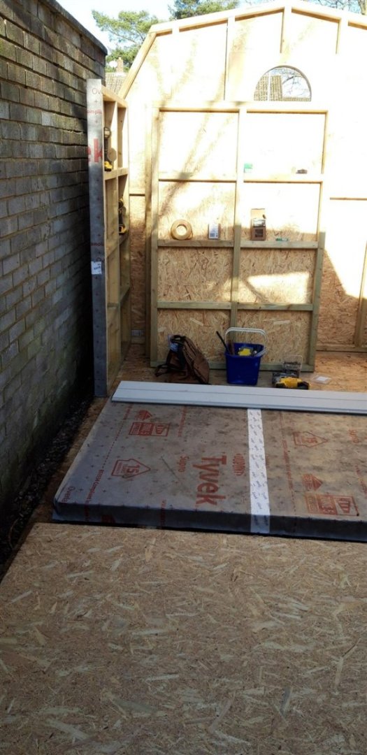
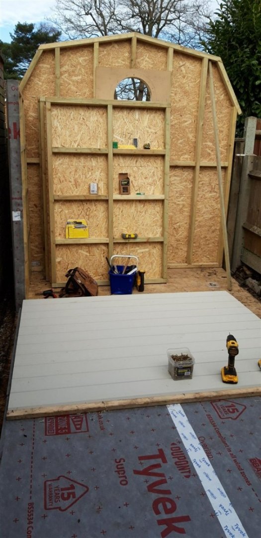
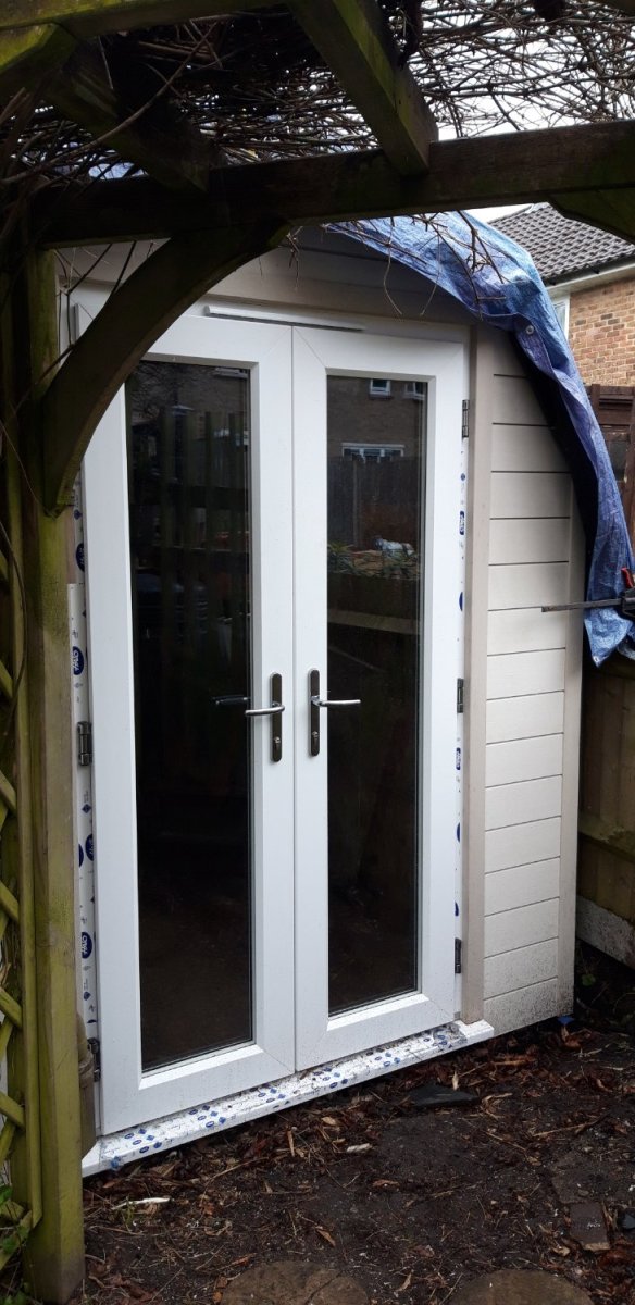
At last the door unit has been installed so the final wall could have its cladding added...

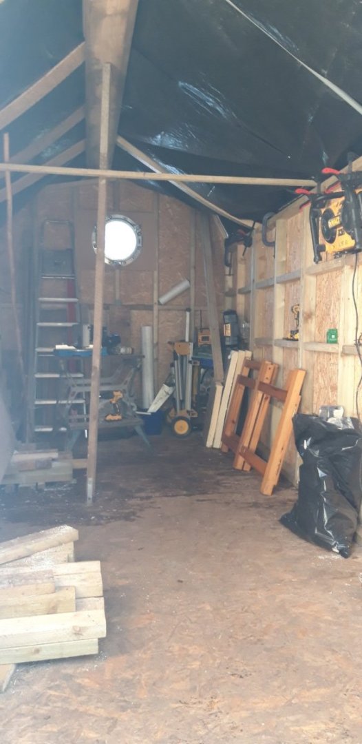
The weather has held things up a bit - its been very wet recently. 'Catch 22' - to construct the roof trusses it helps to have a workshop, to use a workshop it helps to have a roof...... To protect the work completed so far weather proofing has taken the form of plastic sheeting and tarpaulins. A moderately successful solution, but not ideal, and high wind really tests its integrity. It's a bit dark inside, but usable.
Measurements have been taken at the six positions where the frames will be fitted, for each of the four main elements that will form each truss. This has now been drawn out full size on a building board. The structural ply has arrived and my next task is preparing this for assembly. There are 18 parts for each truss frame, and each frame is slightly different to deal with the taper the workshop has in order to make the best of the available space.
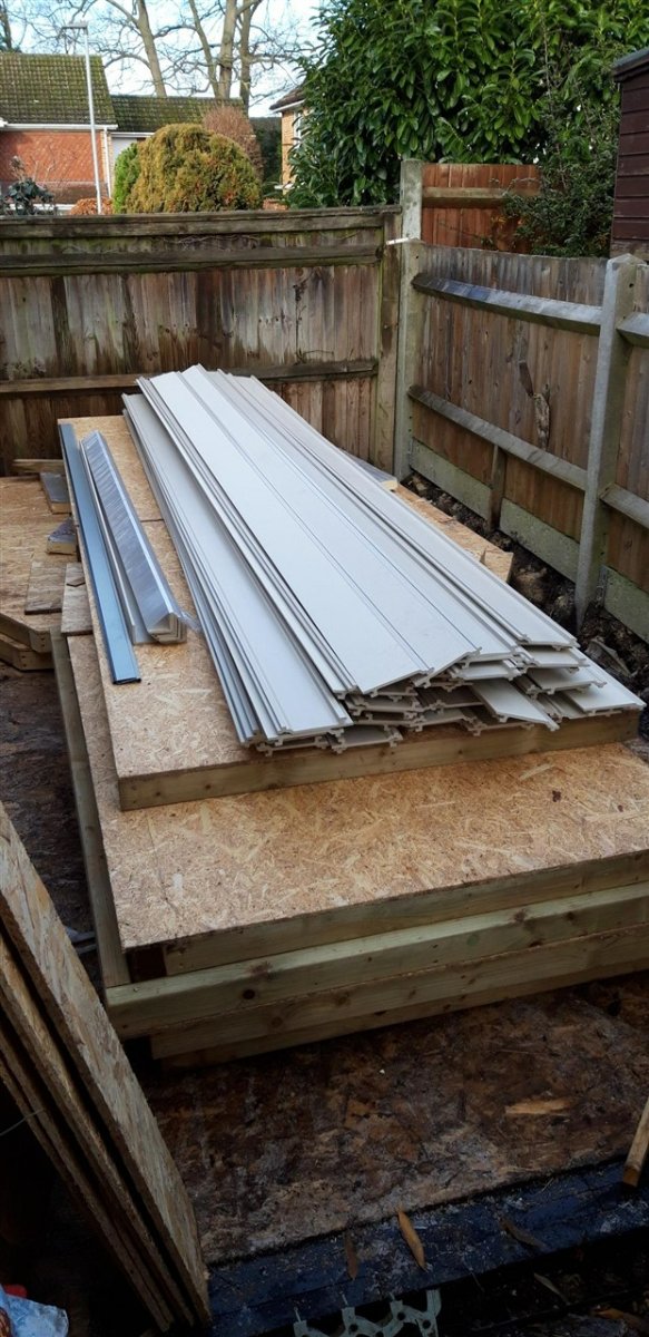
I have also received the six roof lights, bought earlier than needed to take advantage of a bulk purchase offer and to also beat a planned product price rise. These are currently stored in an already very cramped model making room...... but it will be worth it - eventually!
Cheers,
Graham.
- Jack12477, Haliburton, GrandpaPhil and 7 others
-
10
-
-
-
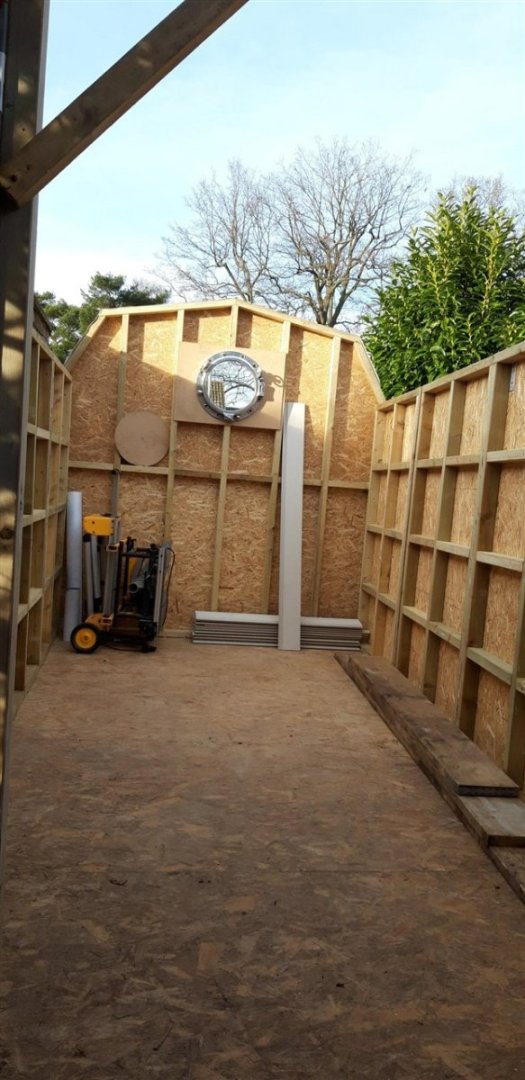
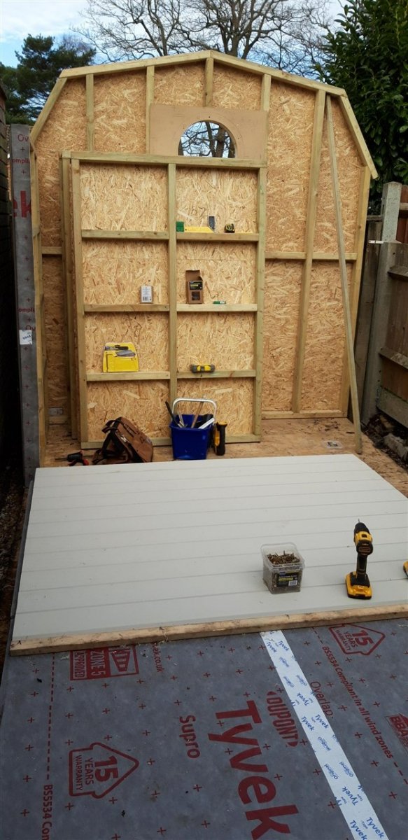
With the arrival of the cladding at last it's time to assemble this large 'flat pack' kit......

The height of the side walls was determined from the standard length of the cladding - 3.6 M. Cut in half and fitted vertically there was no waste. Two panels were clamped together and the run of cladding strips screwed on until the first two lengths were fixed to the second panel. At this point the panels were separated and the finished section lifted and screwed in position.
Confession time.... my original plan was to clad each panel flat on the floor and then lift it and slide it into position. Maybe 30 years ago I could have succeeded ...... managed the first one, just! So a rethink led to the panels being covered in a more vertical position.
The plan worked and each section snapped nicely into place
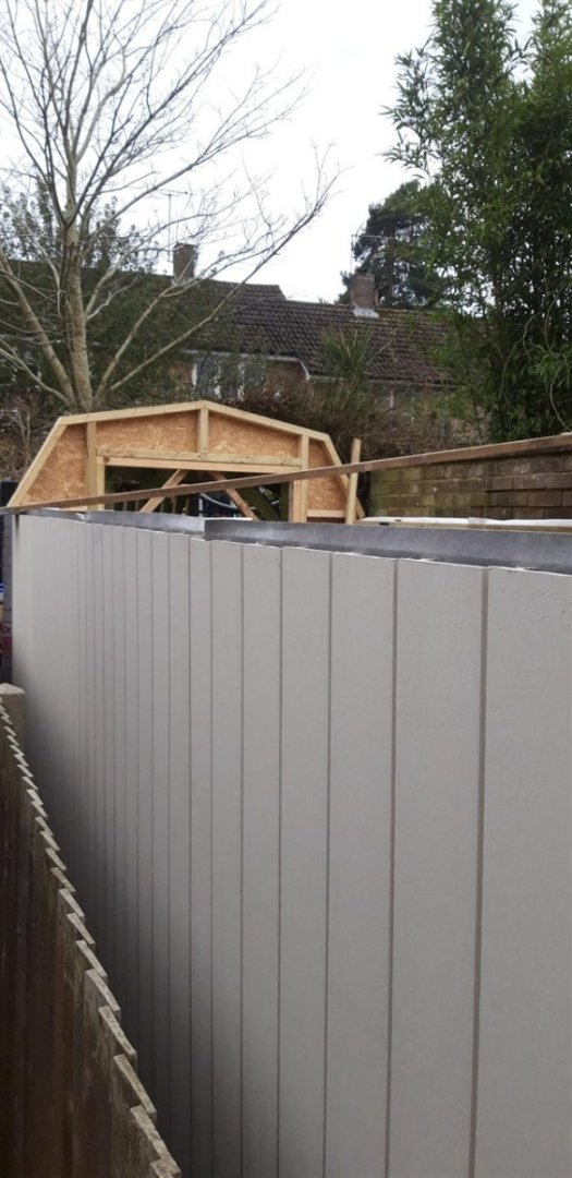
Galvanized 3 x 30 mm straps set into recesses routed into the top of the sections bridging the joints stiffened the structure further.
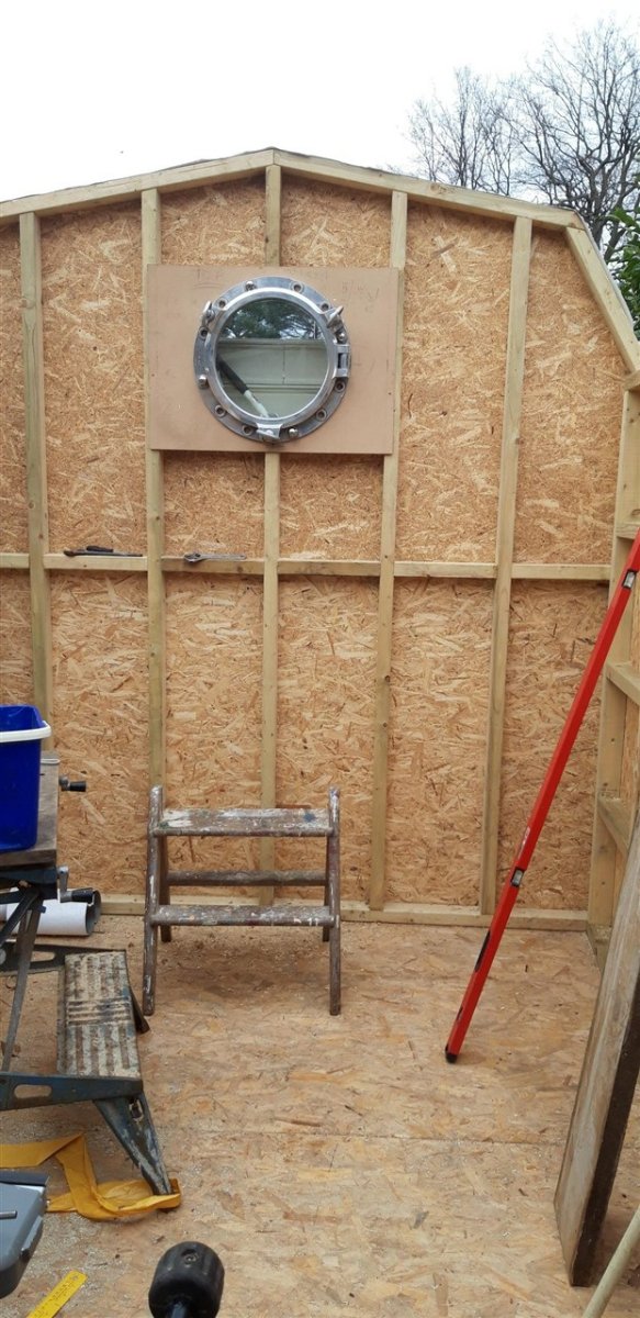
The cladding on the end panels runs horizontally. On the far end the four 20 dia. x 100 mm coach bolts that secure the porthole had to be added first. This meant temporarily fitting the porthole.

Careful trimming with a jigsaw followed by a large drum sander completed the shaping of this feature.
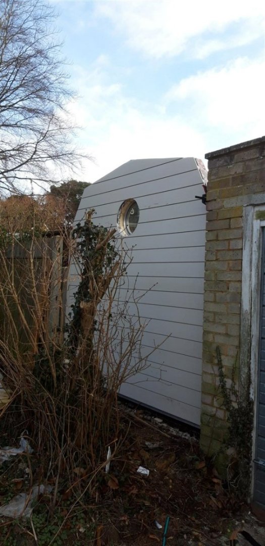
After this picture was taken the fence panel was dragged back into place and secured for the final time.
Cladding the near end panel will wait until the door has been fitted. This is due to arrive at the middle of next month. For now this end has been left with the vapour barrier for protection.
Spent the afternoon clearing up the site and a quick trip to the local recycling centre to dispose of a car full of offcuts etc. that were to small to be of any further use. Also needed to clear the part of the garden I've been using to store materials as the Admiral's spring bulbs are pushing themselves up in the adjacent flower beds!
Time to start working on the roof......
Cheers,
Graham.
- hof00, mtaylor, GrandpaPhil and 9 others
-
12
-
Impressive work with those sails Andrew. The detail on the deck is a whole new level too. Looking forward to seeing that mainsail!
- ibozev, chris watton, Edwardkenway and 1 other
-
3
-
 1
1
-
-
-
Good to see you're back in the shipyard Dave, and your Mayflower is looking great. I will be continuing to follow your progress with eager anticipation!
Cheers,
Graham
-
A beautifully engineered and creative solution to displaying your exceptional Victory build, Robert. Pure genius!
👍
- AJohnson, Ian_Grant and mort stoll
-
3
-
Good idea to extend the trusses down further and widening them where they rest on the walls, Ron. The metal straps I'm thinking of using are 30 mm wide and will screw to the top horizontal CLS timber. I could add them to the sides as well - they will all be hidden once the wall insulation and interior facing boards are in place. I'm also planning to add some additional bracing between the trusses too. I've dropped the number of trusses from seven to six to increase the width between them for the roof lights and one other advantage of this is it moves them away from being directly in line with the vertical wall panel joints.
As for snow loads - this far south we rarely get more than a couple of inches, 4"- 6" is regarded as extreme. Unfortunately in the UK anything above 1/2" is enough to bring traffic chaos and bring the railways to a halt....😂
- Jack12477, Edwardkenway, Egilman and 5 others
-
8
-
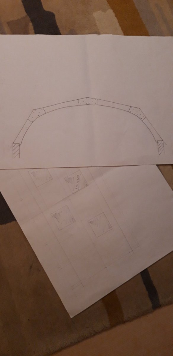
The plan is to build the intermediate trusses using structural ply, Ron. Something like this:

The angles are constant, just the lengths of each member need adjusting, and I can get these measurements once the walls are erected. Fitting six of these trusses will give me room to comfortably fit the 500 mm square roof lights. I'm also planning to re-enforce the joints where the side wall panels meet with galvanized metal straps on their top edge to hopefully minimise any tendency for them to distort under load. Might add some collar ties as well, doubling as storage supports for longer lengths of timber.
Cheers,
Graham.
- mtaylor, Ian B, GrandpaPhil and 7 others
-
10
-
Hi,
Thanks Andrew, it all seems to be coming together at last. Looking forward to completing the weather proof shell so I can work on the interior ..... just the small matter of the roof to overcome, but I'll deal with that hurdle once the walls are finally erected - working out the dimensions of the roof trusses will keep me busy with each one differing in size due to the taper.
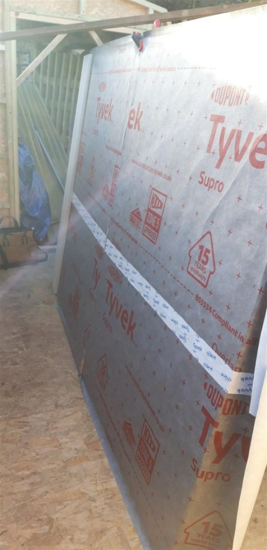
Thanks for the advice Jaager. The condensation issue has been given a lot of thought. The Tyvek is already here and ready. This vapour barrier will go over the outside of the OSB and under the composite cladding. The profile of the system I'm using (Claddo) leaves a good air gap behind it. Wall and roof insulation might end up Rockwool, or possibly a natural wool fleece product. As I hope to spend a lot of time using this building it will need to have some form of heating to make it comfortable in the colder months and also to protect the equipment that will be in it. The French doors have also had the trickle vent option for ventilation too. Earlier in the design process a curved corrugated roof was a strong contender - sort of like a Shepard's hut without the wheels. The difficulty of adding affordable roof lights put a halt to that idea. Not wanting to have a flat roof or a normal pitched roof the 'gambrel' style seemed a workable alternative, the inspirational spark for this actually came from Knocklouder's pictures of his vegetable and herb garden!
The products Kalwall produce are very impressive but unfortunately my budget is definitely limited! I have found a small company in West Sussex called Activent who specialise in roof windows, fixed or opening, single or double glazed, specifically for wooden garden buildings. These seem ideal for my purposes and I'll probably go for the fixed double glazed version with an opening one for those times when a bit of extra air flow is need.
Grotty weather back in force today, but the cladding order has now been placed and it's arrival eagerly awaited!
Cheers,
Graham.
- Edwardkenway, Jack12477, Canute and 6 others
-
9
-
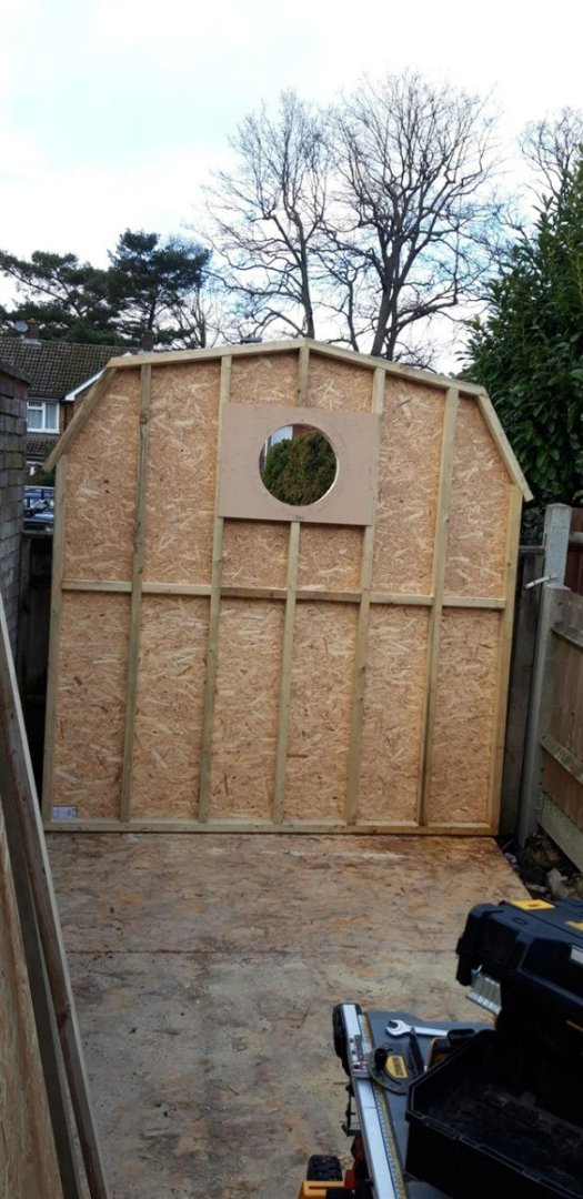
The weather, plus seasonal events have slowed progress down but today, the first in a while with no rain forecast, enough work has been done to warrant an up-date.
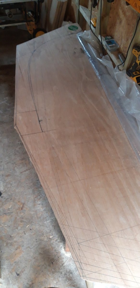
Christmas Eve: I made a MDF routing jig for the porthole which includes the position of the mounting holes. The plan is to use four 20 mm x 100 mm coach bolts with dome head nuts for the main fixing but with the remaining holes covered with the same nuts but on dummy wooden pegs to save a bit on the expense.
The position of the porthole has also been lowered a touch.
A profile cutter in the router shaped the additional timber framing.
_1280.thumb.jpg.d9e4ecbf9e6a57d6cea9d1c3d2b9c486.jpg)
After roughing out the hole in the OSB board with a jigsaw the opening was worked from the other side with the router.
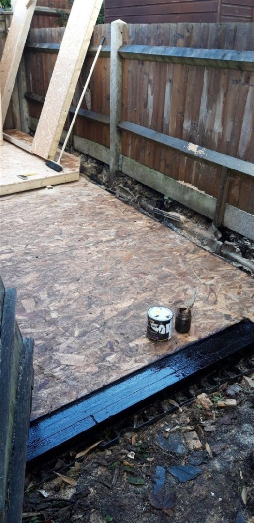
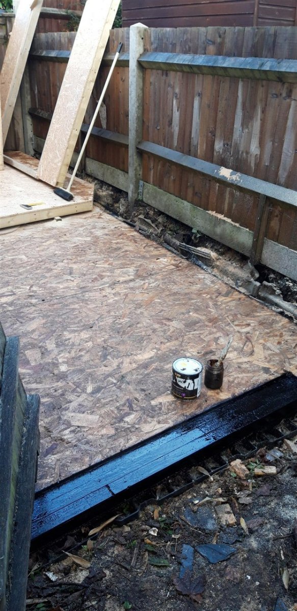
Today, after machining the recess for the door cill, all external edge timbers of the base were given a couple of coats of bitumen paint to seal and improve water resistance.
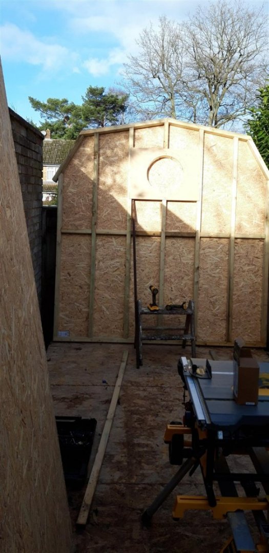
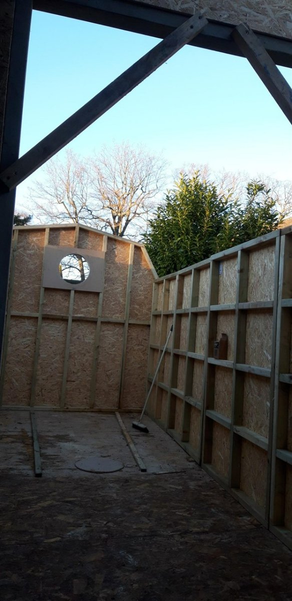
The final wall panel, the near gable end with the French doors, was framed up on top of the far wall to ensure the roof angles were maintained.
It was built around a temporary timber door frame made to the exact size for the unit on order.
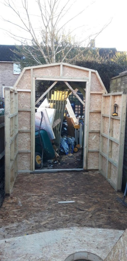
Couldn't resist the temptation to slot it all together........ just to check....

With the sun beginning to set it was time to return it all to it's flat pack form and under tarpaulins to await the arrival of the composite wall cladding.
Happy New Year

-
Hi Bruce,
Not to sure if this technique would be appropriate as I don't know if it would work for your particular application, but one trick I use when wood turning is to glue wood together with standard PVA, but with a piece of paper in the joint. It holds things together well enough for quite aggressive shaping but can be split apart once the job is done. A sharp chisel usually does the trick. The paper/glue left on the joint surface can then be sanded or scraped off.....
Another possibility might be to use a hot melt glue and then heat the wood after shaping. Seen this done but to be honest I haven't tried it myself.
Good luck!
Cheers,
Graham.
- Canute, mtaylor, Keith Black and 1 other
-
4
-
Excellent work there Ron.... looking good...👏
- kiwiron and The Gimps Chimp
-
1
-
1
-
Well.... what a day!
This could just as well been posted in the 'What have you received today' thread 🙂
I wanted a window in the far gable end that would increase the amount of natural light to the 'clean/dust free' model making section of the workshop (the Captain's day cabin?). I thought it would be appropriate to have some sort of nautical theme as a nod to the workshop's primary use and have a few ideas about how to do this. Then the Admiral asked for ideas for a Christmas present. "A porthole would be nice...."
Today we drove over to Trinity Marine near Exeter. Remember when you were a child and were taken to the most amazing toy shop and you felt like all your Christmases had come at once? This marine reclamation/salvage company has some jaw dropping stuff. Their website is impressive, but really does not do justice to the stunning stock they have - for example the very detailed model paddle steamer that currently has pride of place in one of the two display showrooms -it must be at least 8' long, or the model of a French frigate, or the gear reclaimed from HMS Hermes....... To call the place an Aladdin's cave is an understatement and I recommend a visit if you are ever in the area.
trinitymarine.co.uk if you want to browse their website.
So, I am now the proud owner of a 19" diameter, aluminium opening porthole reclaimed from the MV Orient Well.
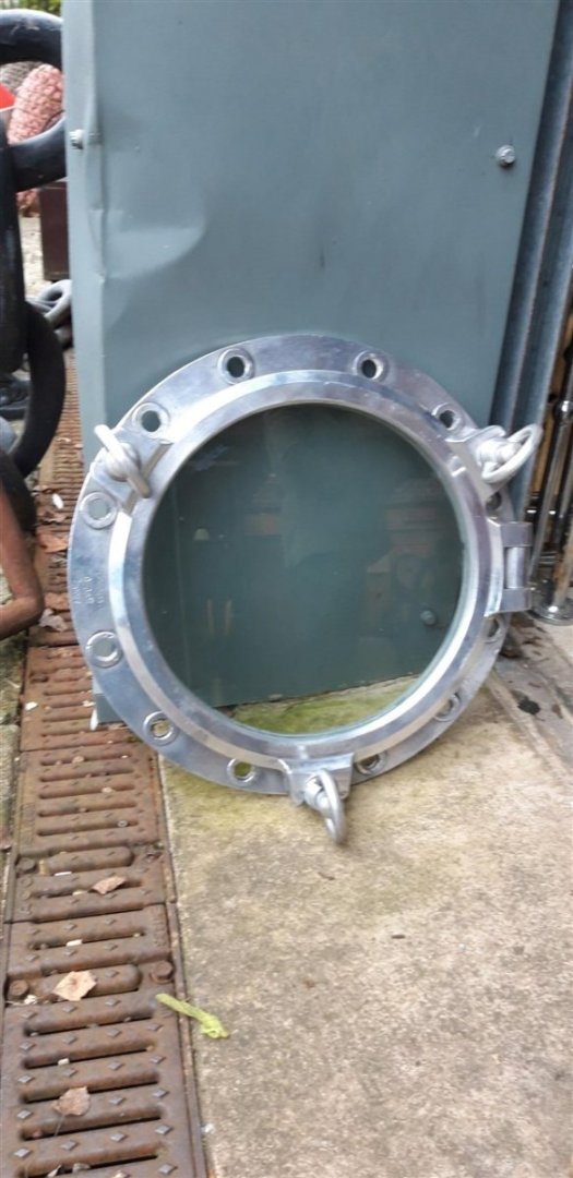
and one of my next tasks is to adapt the timber framework to accept it.
Christmas has come a bit early this year 😁

Ho ho ho
Cheers,
Graham.
- gjdale, Edwardkenway, king derelict and 15 others
-
13
-
 5
5


_1280.jpg.d33180424abd8a9617587193b3566d2a.jpg)


Woodwork/Model making workshop. Scale 1:1
in Non-ship/categorised builds
Posted
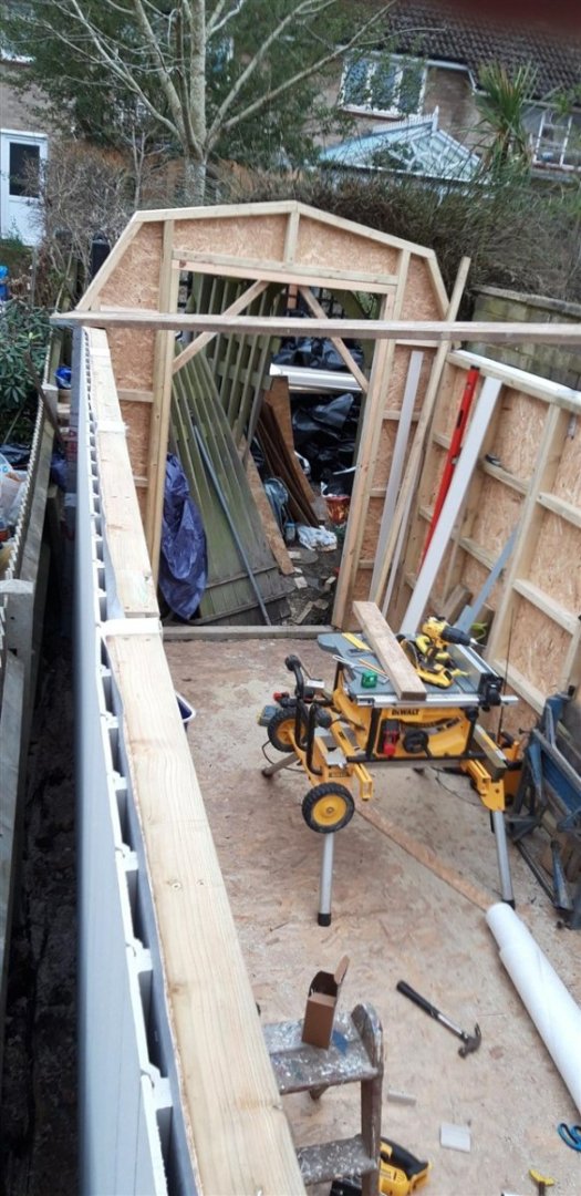
Well.... I could say that everything went as planned ..... but I'd be lying...
The widths of each frame were spot on, but a couple of them needed a bit of tweeking, trimming or packing to to get them aligned to an acceptable standard. Took a full day to get them set up and to cut and install the top ridge.
Today the side ridge spacers were slotted into place and finally the knees were fitted to brace frames and secure them to the side walls. All is now nice and rigid. Bit like making the tackles for every middle deck gun, the knees will all be hidden eventually, but we know they're there....
Next task will be to add the ply sheets. In the mean time the plastic sheeting and tarpaulin are back in place in anticipation of the heavy rain and thunder storms that have been forecast.
Cheers,
Graham.