

No Idea
-
Posts
902 -
Joined
-
Last visited
Content Type
Profiles
Forums
Gallery
Events
Posts posted by No Idea
-
-
Hi Chris - I had a similar issue with the belt rubbing on the guard at the motor end. After speaking to Jim he suggested that the motor tensioning spring was probably not as it was. So he suggested that I place a few small washers behind the spring and this solved the problem. It pulled the motor further up and also gave more tension on the belt. Even now I only have a small gap between the belt and guard but it certainly solved the problem - Mark
- Roger Pellett, Canute and mtaylor
-
 3
3
-
Simple amazing work - I can’t thank you enough for sharing your skills as I personally have learned so much from your log 👍👍. I’m looking forward to your next build 😎
- robert952, mtaylor, MAGIC's Craig and 1 other
-
4
-
-
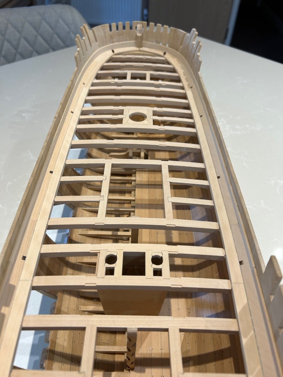
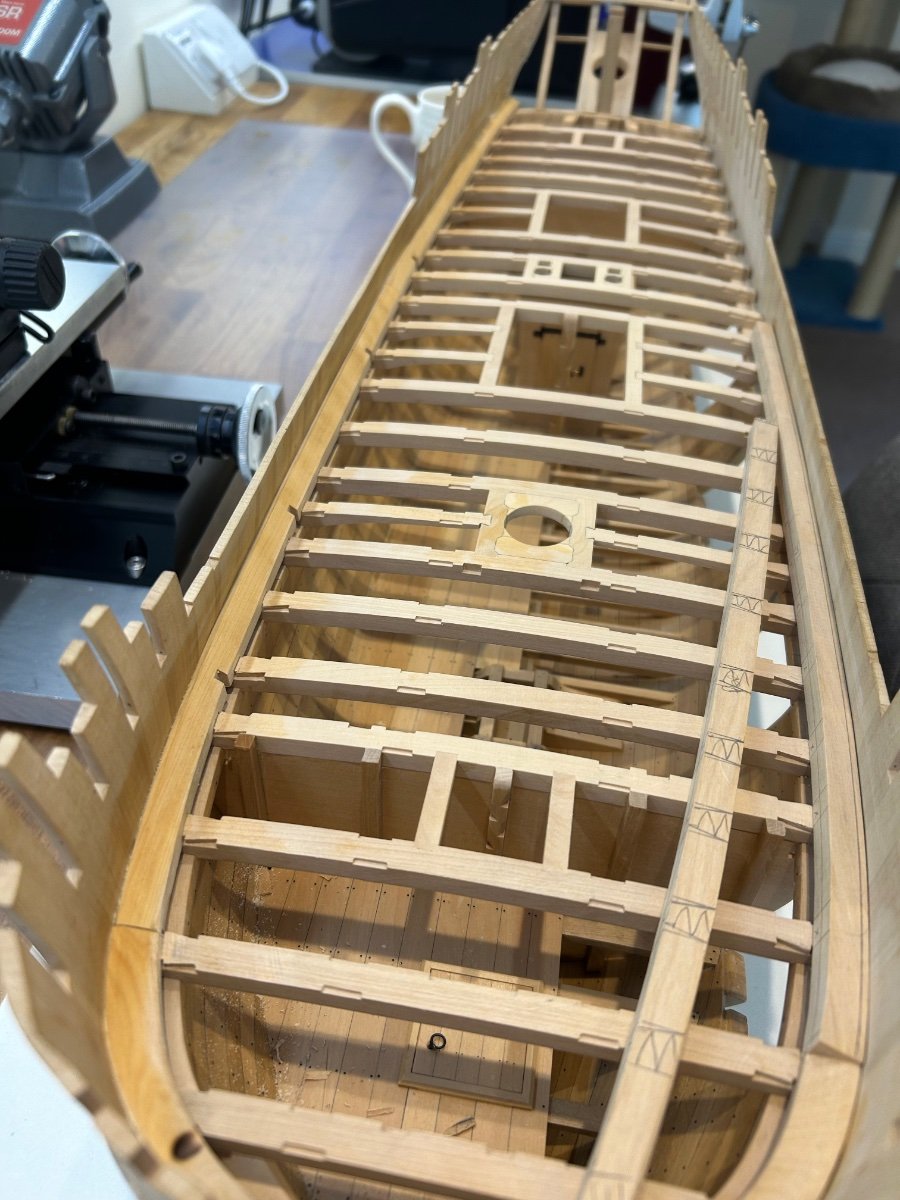
Another update from me - The inner waterway which is pretty much more of the same but is easier to make. Its made up of three sections per side.
The parts were then glued into place - I found that the dovetails pretty much hold these parts in their correct place. They do nee to be clamped though to bring them down to the sheer.
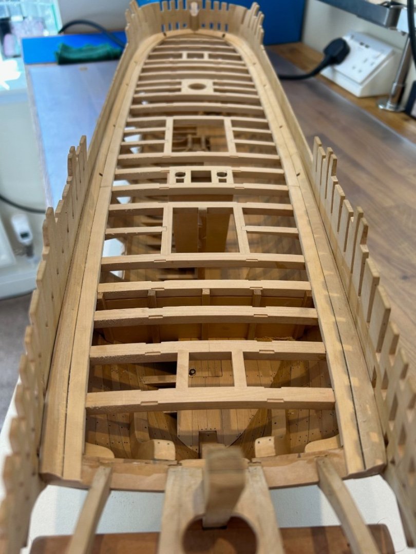
Then I made and fitted the first plank up the bulwark so that I could finish the bevel on the waterway. This was then all sanded down and blended in and I'm pleased with the result.


So thats brings another part of the build to conclusion. The next job is to make the binding strakes.
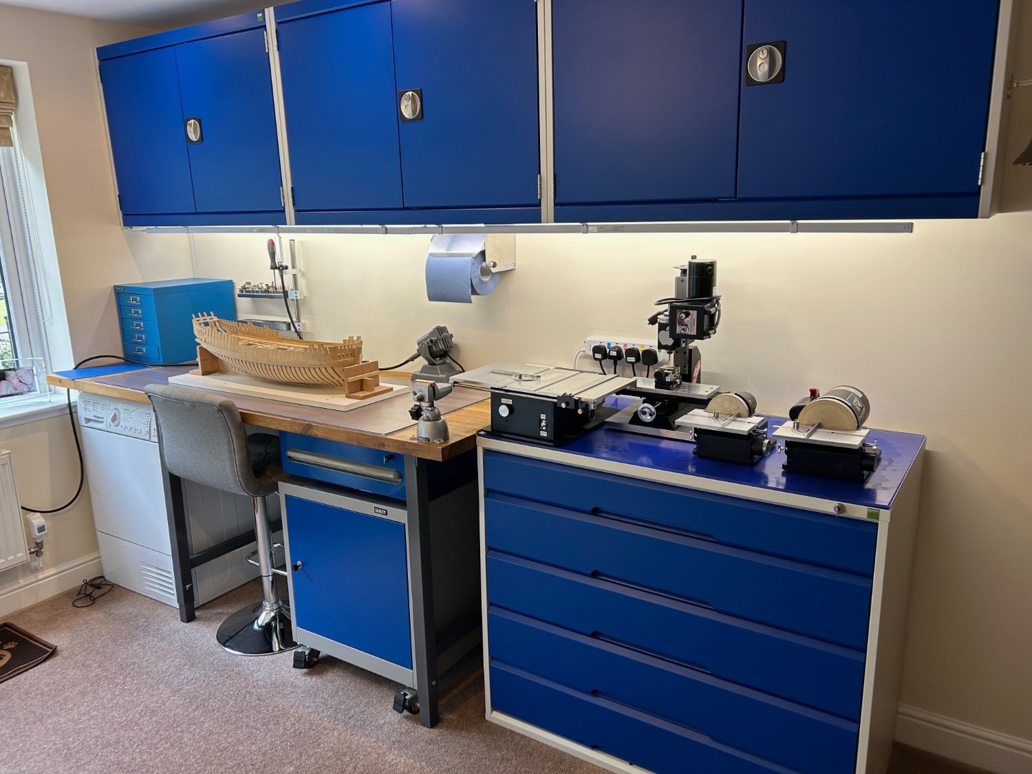
@DaveBaxt this is where I work - Its not a big area but I find it more than adequate. Its always this tidy as its our spare room so I need to make sure that the mess is always cleaned up.

Cheers Mark
-
6 hours ago, DaveBaxt said:
Great to see you hard at it Mark in these few summer months when usually things are a bit quiet . Your workmanship is something to behold and perhaps one day If possible I would like to view your setup . Cheers for sharing your build with us. Dave
Hi Dave and thanks very much - I'll get a couple of pictures up of my work room sometime this week so that you can see where how it's all set up. Prepare to be underwhelmed though 😆
3 hours ago, druxey said:Those waterway pieces are seriously impressive! Well done. Mark.
As always mate - thank you. I know I've said it many times but those parts are very difficult to make. The shape changes constantly and if you get the angle wrong there's a gap somewhere. The pay off though I think for any builder is when they eventually just click onto the mating dovetails need very little clamping. This is why I build - the feelings great.
37 minutes ago, Hubac's Historian said:I continue to be amazed by your care and craft, Mark. The work is so clean!
Thanks HH - I actually think its the other way around - Its your work thats clean and never ceases to amaze!
I made a start on the inner waterway and I'll get some pictures up this week. Having just finished my nemesis parts I was expecting more of the same. But no................hooray its not the same at all. It's a much simpler part to make......well so far anyway! I have discovered that the dovetails on the beams are a little short and I think this is yet again down to my photocopier. Its no big deal really I just need to take my time.
Cheers Mark
-
Honestly thanks for the very nice comments and the likes here - I won't lie I have found these particular parts very difficult to make and get a good fit. You have very much helped me through this particular part of my build. If anyone else is building Le Rochefort you don't have to cut the dove tails if you don't want to. You can simply cut a slot the width of the beam and it would be so much easier. I did it this way as I just want to make it as true to the drawings as I possibly can. However once done how satisfying is that feeling 😀
So I carried on cutting out the dove tails and also roughing out the bevel


After a little fettling they did fit


As always I've learnt some new skills and overall I'm very happy with the way these parts have turned out. You can see that I have also rough cut the scuppers too. My patience is definitely improving too which I like. So now that they are installed I can now start on the inner waterway.
Cheers Mark
-
Hi Bob - yes I do use these but it's the deep reach that I need. I do have lots of types of clamps including G clamps but I think the type I'm looking for will be very useful.
- mtaylor, thibaultron and Canute
-
3
-
-
Hi Everyone
Can anyone help me - I want to get some of these small C/G? Clamps and I cannot find them anywhere.
If someone could please point me in the right direction I would greatly appreciate it.
Cheers Mark

- Canute, thibaultron and Archi
-
3
-
Congratulations Chris that really is a beautifully made ship.
- AJohnson, Keith Black, mtaylor and 1 other
-
4
-
-
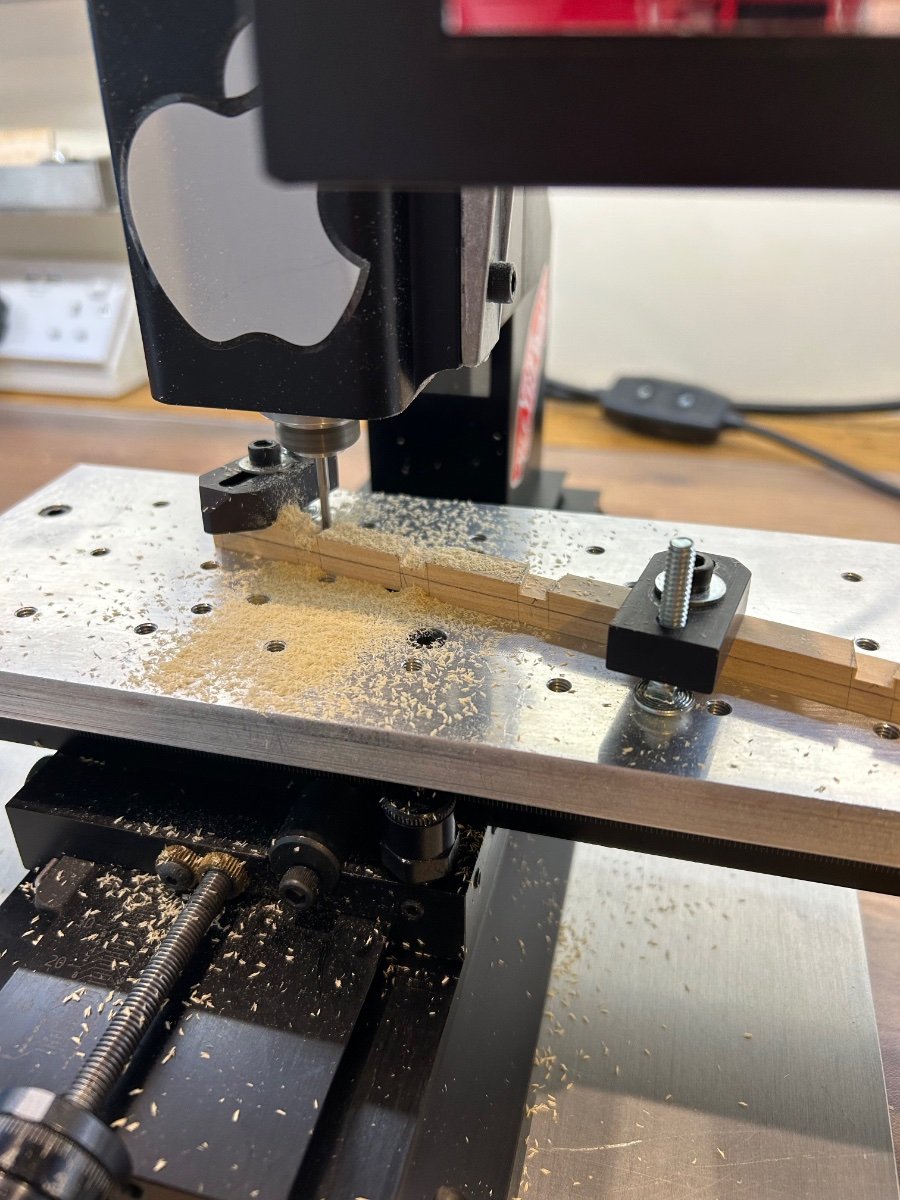
Just a quick update - I've now rough finished and loose fitted one of the parts.
I cut the dove tails on the mill and they needed just a little adjustment to fit onto the beams
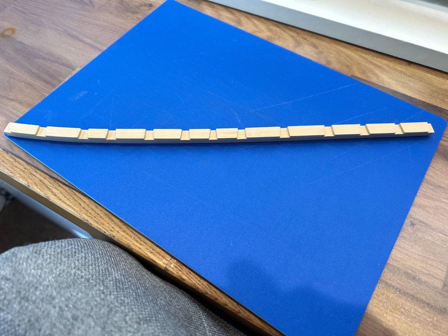
I also roughed out the inner bevel partly to make the piece slightly more flexible to fit the curve of the deck. It actually fits ok and pretty much just clicks into place but it will fit a lot better once clamped and glued. It will require a little blending into the adjoining pieces.
The bevel will get its final shape once the inner waterway is made and fitted and also the bulwark plank above. So far so good - and it's nice to be moving forward again. I'm starting to feel a lot more positive regarding these parts. I'll update again once the rest are completed
Cheers Mark
-
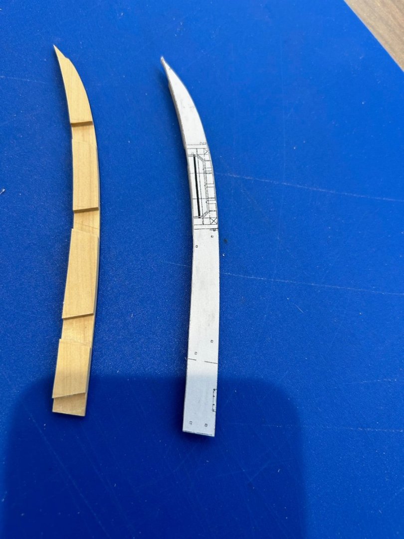
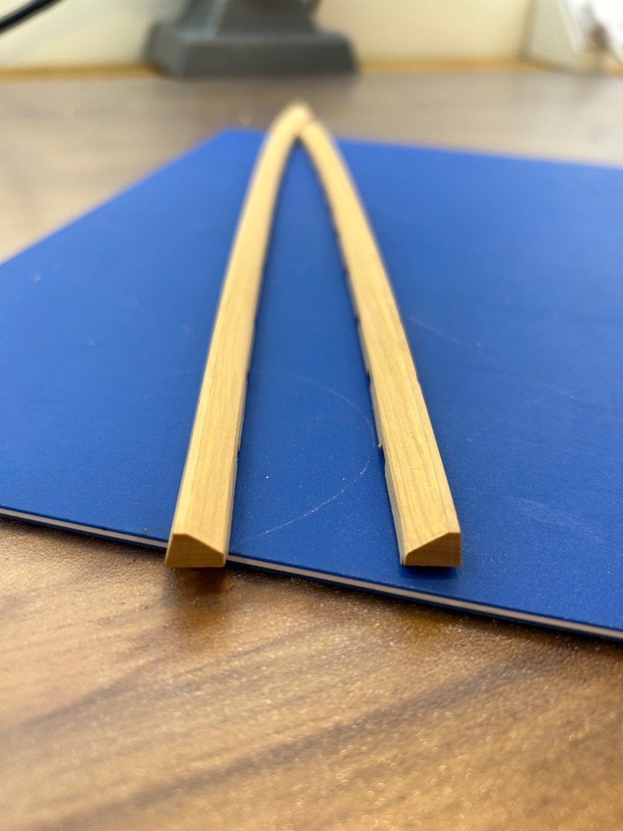
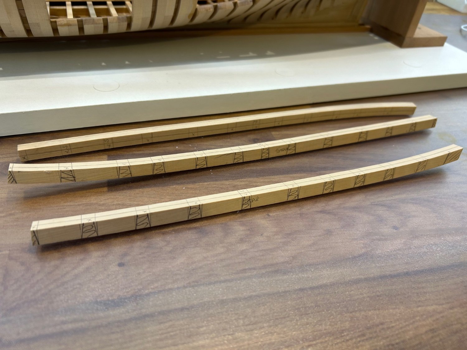
I'm actually starting to get there - One of the pieces took me four goes to get right. I discovered that if the bevel angle between the beam and frame is wrong the dove tails on the beams will not line up to the tune of about 2mm out. So after much sawdust I've now got the roughed out pieces to sit right on the beams. This actually doesn't look like much but I've found this difficult - Its like working upside down and I think it's one of those parts that you need to make to see what I mean. So a couple of pictures.


I think these pictures give a better idea - here's the transition of one part from one end to the other


So I've now marked out the dove tails as best that I can and that will be my next job of cutting them out. I've also cut the holes for the scuppers which was not a great success - I've drilled them at a very shallow angle and also burnt the wood in the process. All is not lost here though as they will need lining with pewter in the manger so I can hide my mistakes then. As always you get the successes and the errors with me!
So the milling machine is coming out tomorrow and hopefully they will fit ok. If you think that my marking out is a bit rough I kinda have my own method that I understand once I get cutting.
Cheers Mark
-
Fantastic what a great ship to build and what an amazing start - I'm in!
- mtaylor and Greg Davis
-
1
-
 1
1
-
B-Ram luck with your build I'll follow along mate 👍
-
Goodness me that is beautiful work - that dividing head for you mill looks the business and I must get one of those.
- billocrates, KentM and mtaylor
-
3
-
44 minutes ago, druxey said:
Nice analysis of the changing waterway shape. I imagine that you will nail it, given your track record!
Thanks for the vote of confidence - These really are not easy pieces to make if you want them to fit correctly. I'll get there I know that I will but I've scrapped two attempts but my third is just about spot on.
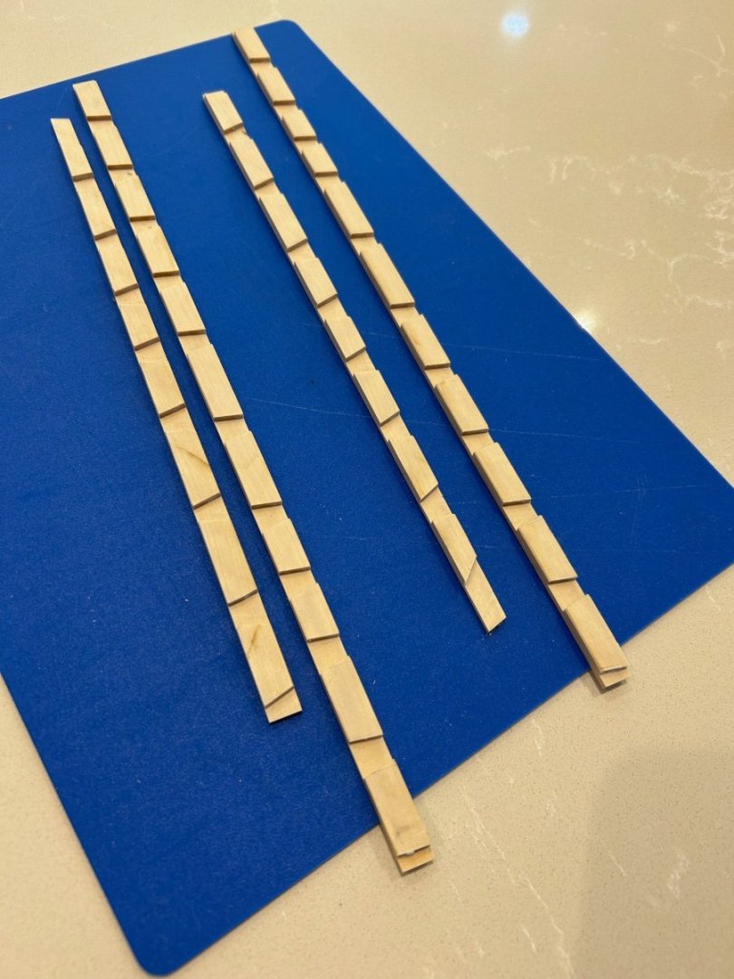
10 minutes ago, Keith Black said:Mark, what is the length of each spirketting? Will they be scarfed or butt jointed? You're doing absolutely beautiful work.
Hi Keith and thanks mate! The forward piece is about 340mm long and the rear 300mm long. They are a simple butt joint and thank goodness for that! Over the length of the forward part the angle changes over its length by about 18 degrees. It's quite difficult to describe in words but you have to work upside down with your measurements as the widest part is at the bottom. Its tricky but I will do this.
-
On 6/18/2023 at 5:23 PM, DaveBaxt said:
Unbelievable workmanship!
Thanks Dave
This is not really an update as I'm not that much further forward. I've finished my decorating and have been putting quite a few hours into Le Rochefort.
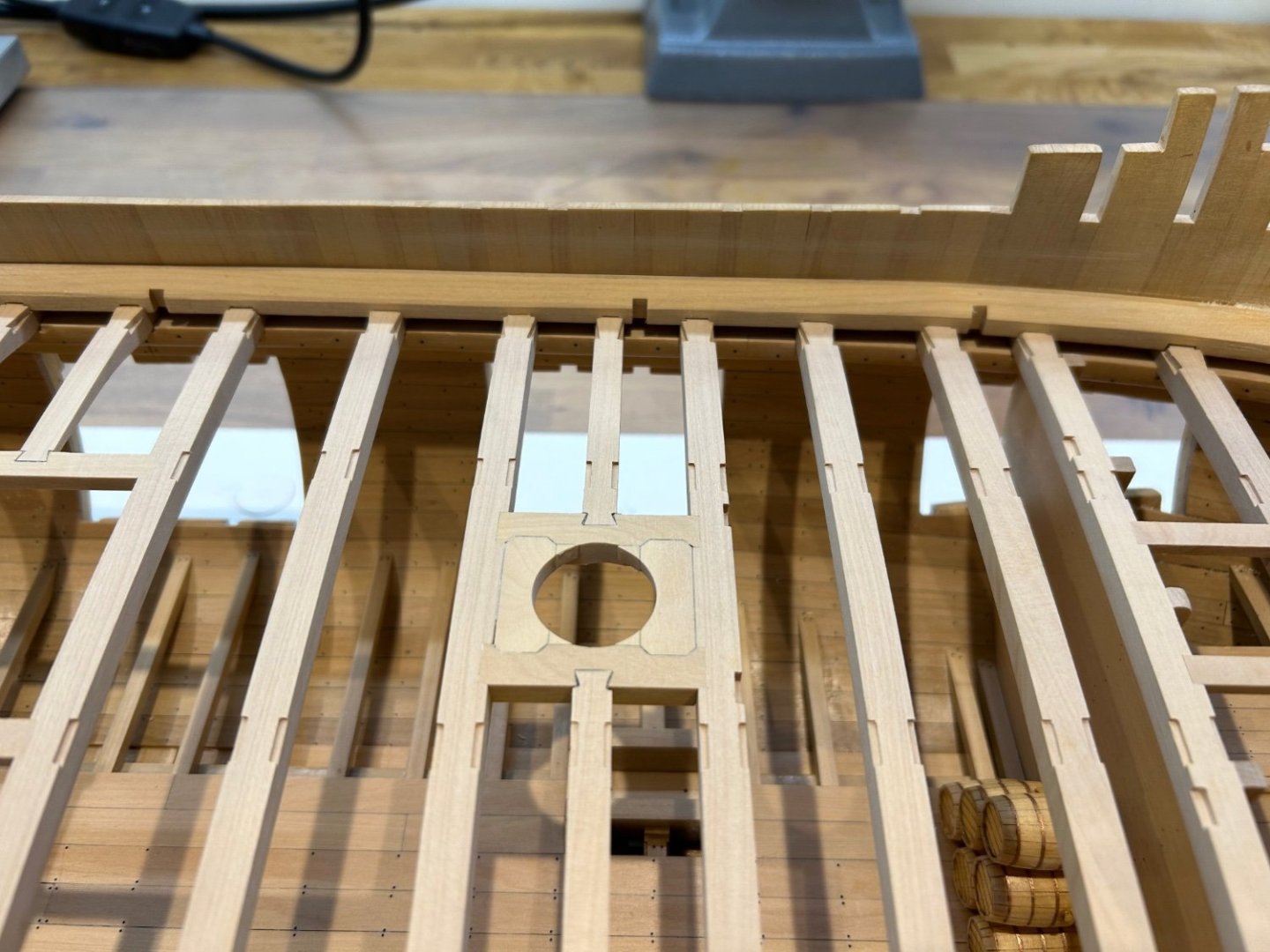
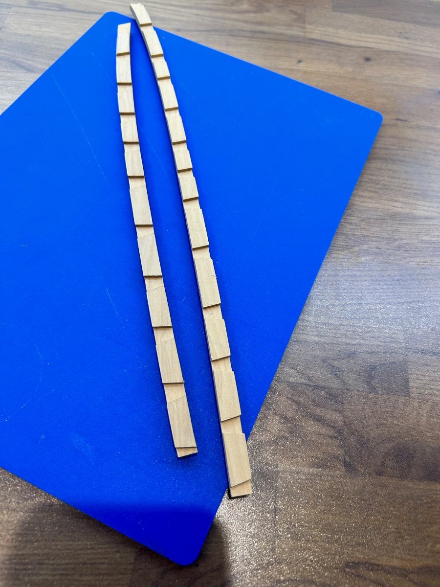
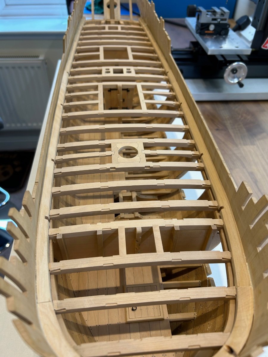
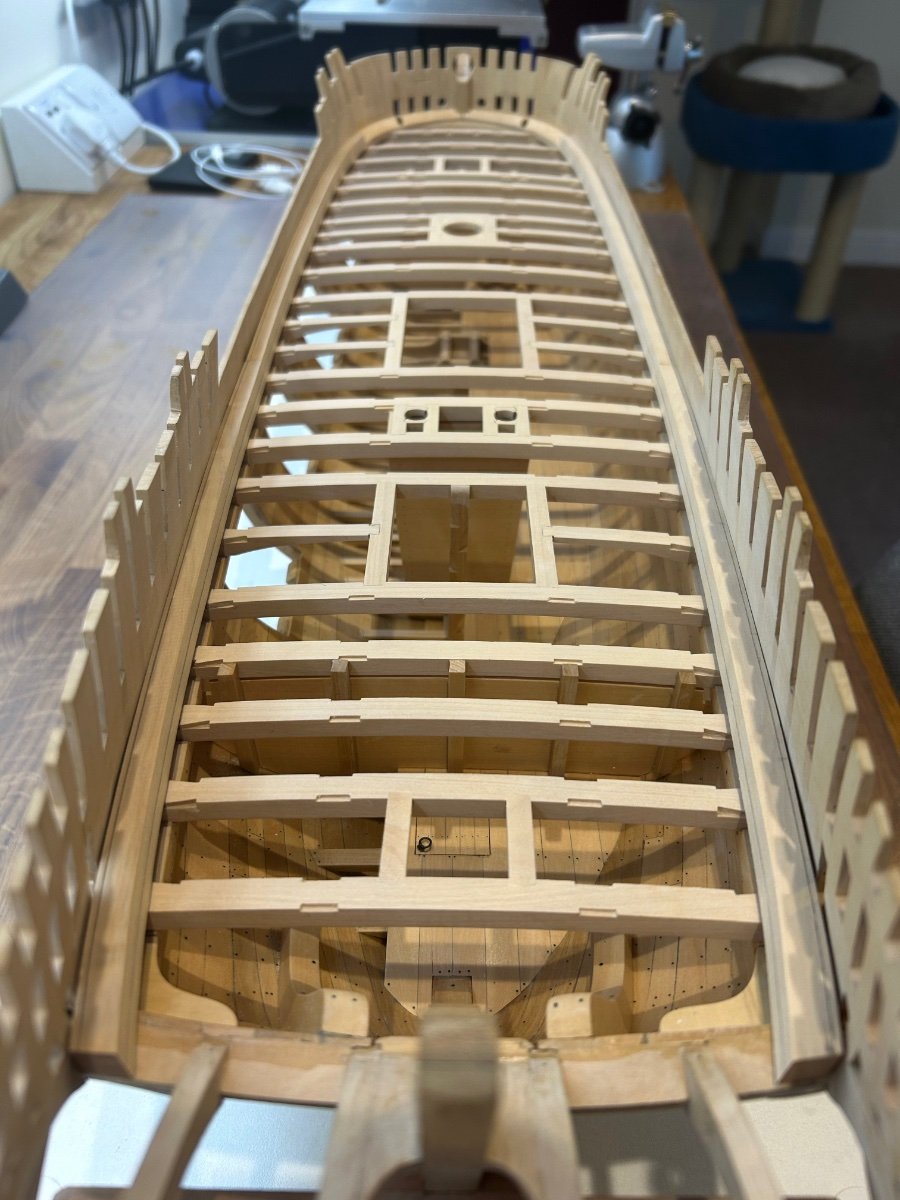
I've just hit a hard bit of the build for me and it's taking time. I have incorrectly been calling these parts the waterway, but when having referred to the drawings they are in fact the spirketting which I guess makes up part of the waterway. Goodness me this is a hard piece to make correctly at this scale. I need the pieces to sit squarely on the beams and also have the correct angle from the clamp to the frame. They also have to follow the shape of the hull so it's a changing 3D puzzle. They are roughly 9mm square and if the shape isn't right and I clamp them in place (force them) I can foresee unnecessary stresses being built up in the hull.
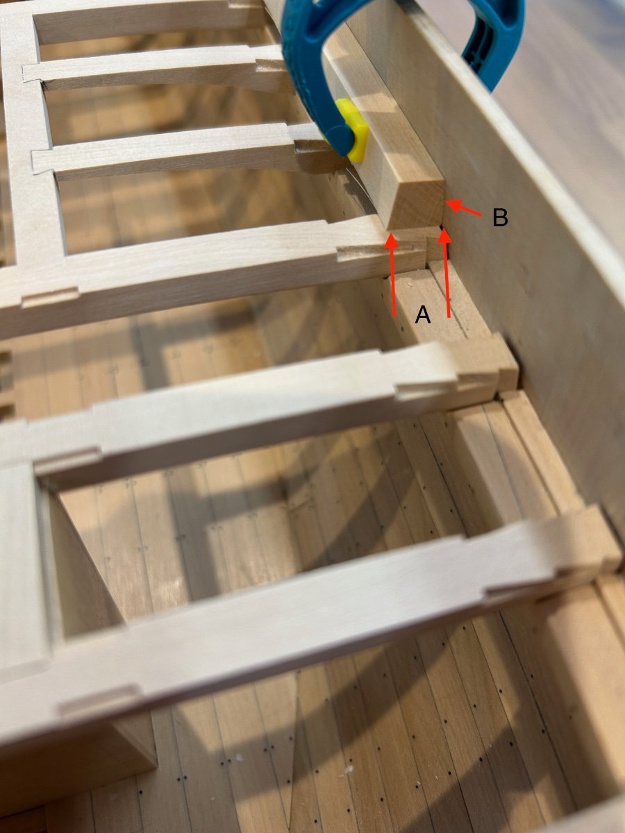
Here's a picture that explains what I'm trying to achieve. Width "A" is not a constant - It varies throughout its length. To make things even more exciting angle "B" also varies along its length from being 90 degrees square to a negative 18 degrees.

Anyway I will get this done it's just taking a lot of time to do correctly. I like to share these issues so that other builders can see the problems that I encounter along the way.
Cheers Mark
-
-
Welcome mate from another UK builder 😀
- Keith Black, Eindride and mtaylor
-
3
-
-
I used to do a lot of spray painting and we removed the step whilst the paint was still slightly tacky.
We removed the masking tape and then ran a finger along the line before it had fully set. This removed the step entirely - however after the paint had fully set....
- mtaylor, Knocklouder, Canute and 1 other
-
4
-
2 hours ago, druxey said:
Well done!
Thanks druxey another hurdle sorted in my build
1 hour ago, Beef Wellington said:Thats fantastic work Mark, beautiful joinery! I love seeing the detail of your approach to these complex pieces.
Thanks BW - I found the hardest part of making this piece was keeping it flat on the beams and breast hook. It would have been easy to force it into place with clamps and I guess it would look the same once glued in. But the challenge for me was to make it fit like it dropped into place and was snug on its adjoining joints.
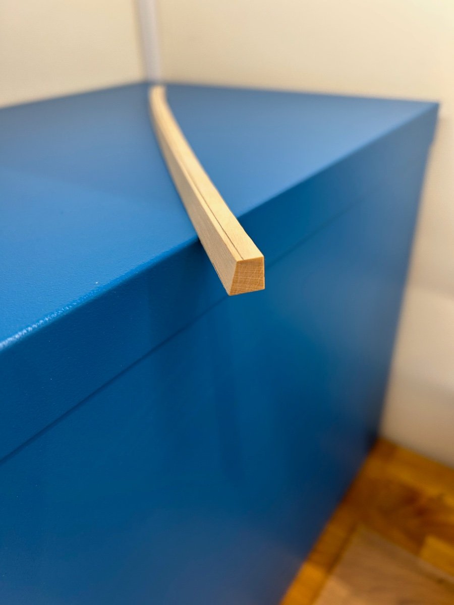
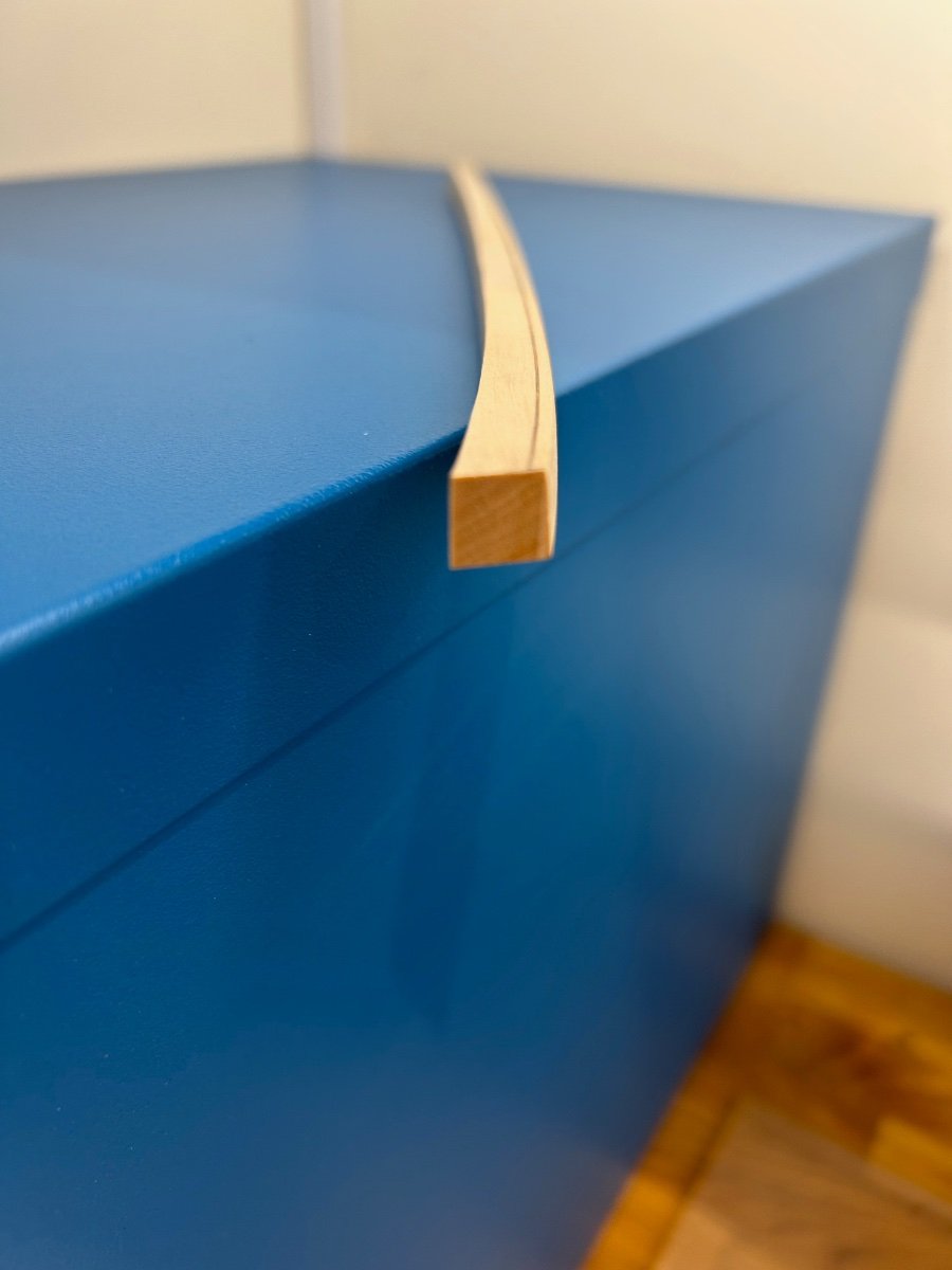
I was really hoping to make the next piece along out of a straight piece of timber and bend into shape. Unfortunately at 9mm x 9mm square its not going to happen so I'll fashion the next pieces too..........well after my decorating is done 😆
Thanks all for the nice comments too 👍
- druxey, Beef Wellington, CiscoH and 5 others
-
8
-


Le Rochefort by No Idea - 1/24th Scale - First POF Build
in - Build logs for subjects built 1751 - 1800
Posted
Hi Marc and thanks for you comments - You are right in some ways that everything is on show and it needs to be accurate but as I have discovered there are loads of ways to hide small errors - thank goodness 🤣
Sorry for the lack of updates I'm just really busy elsewhere at the moment so I fit in the ship building as best I can.
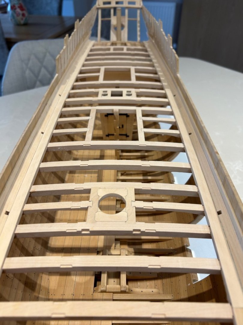
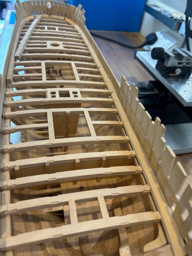
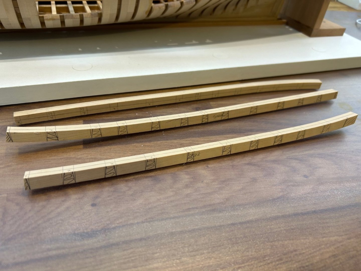
So onto the binding strakes and I soon realised that there is an easy and hard way to make these pieces. As per usual I chose the hard way in my opinion to get better results.
The first front pieces at the bow are simple and pretty much more of the same. Cut them to length and carefully mark out the cuts and get going on the mill. It's difficult to explain my weird markings on the pieces that I cut too, as I use them as a guide to what I know to be correct in my mind? It works for me - it's not for everyone.
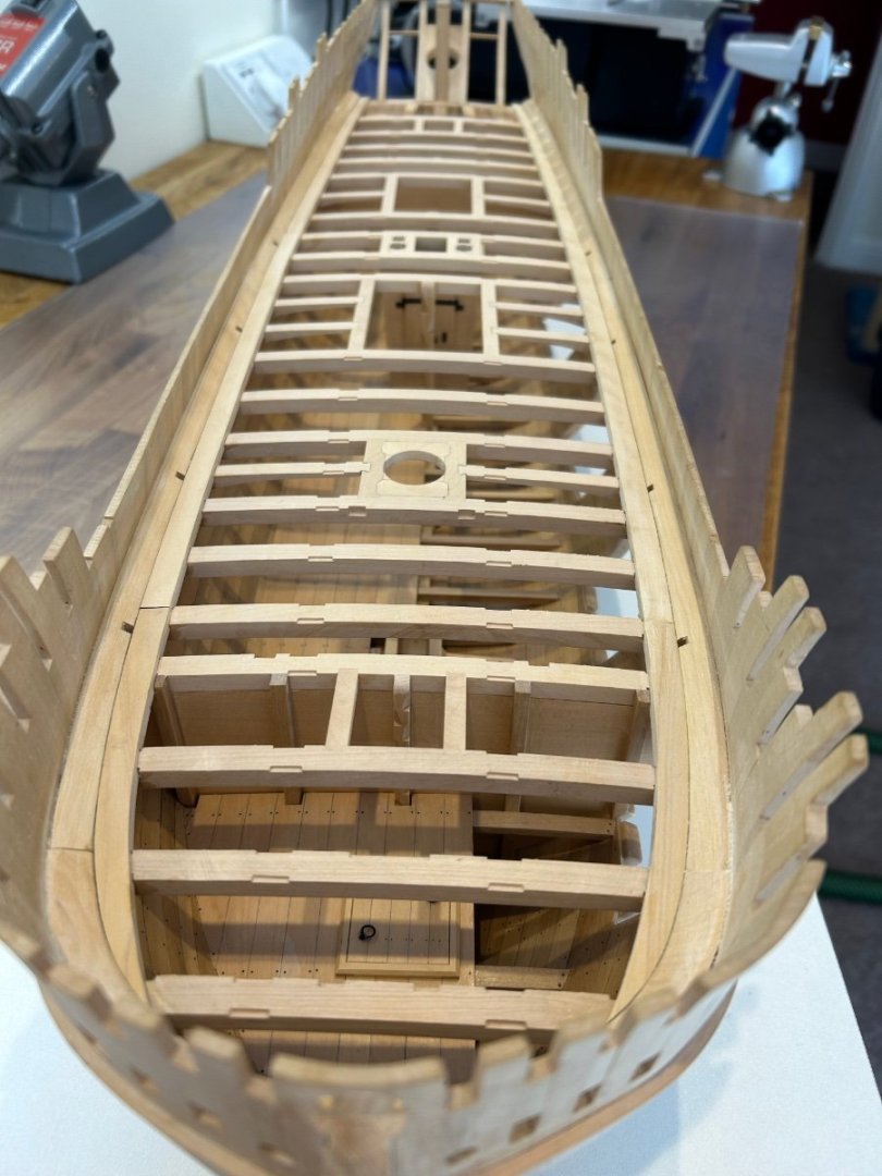
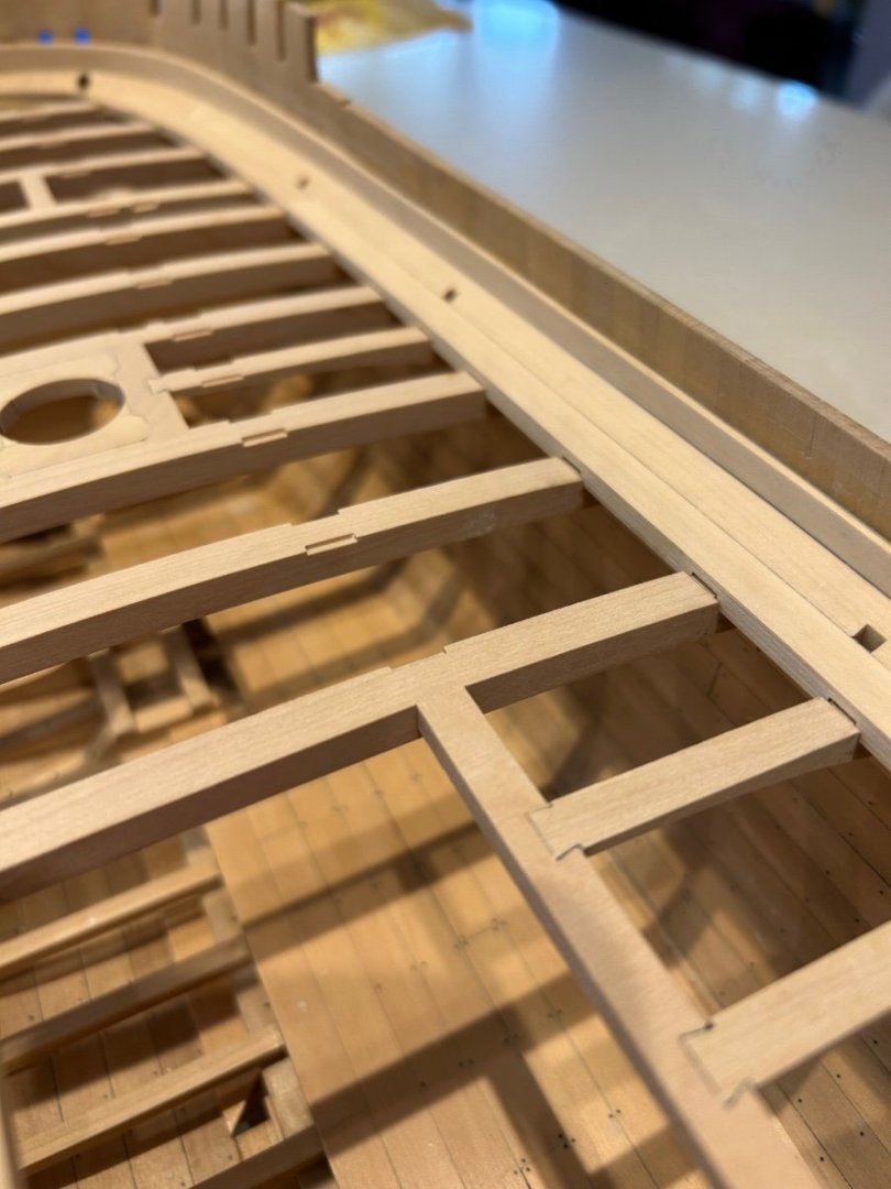
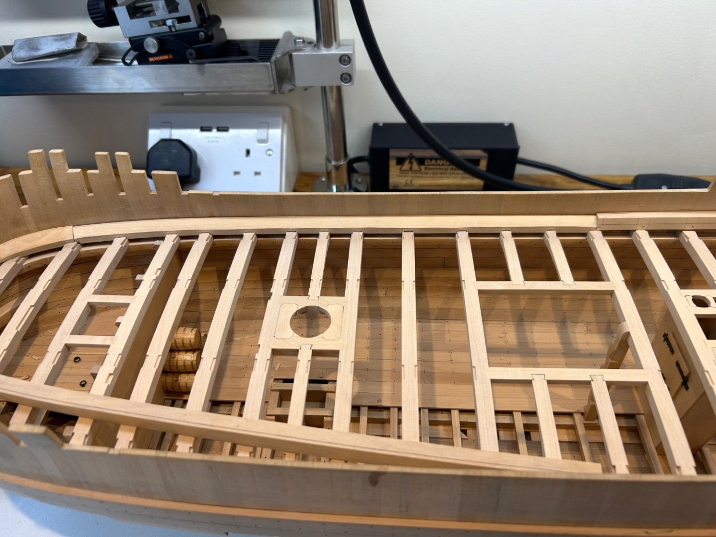
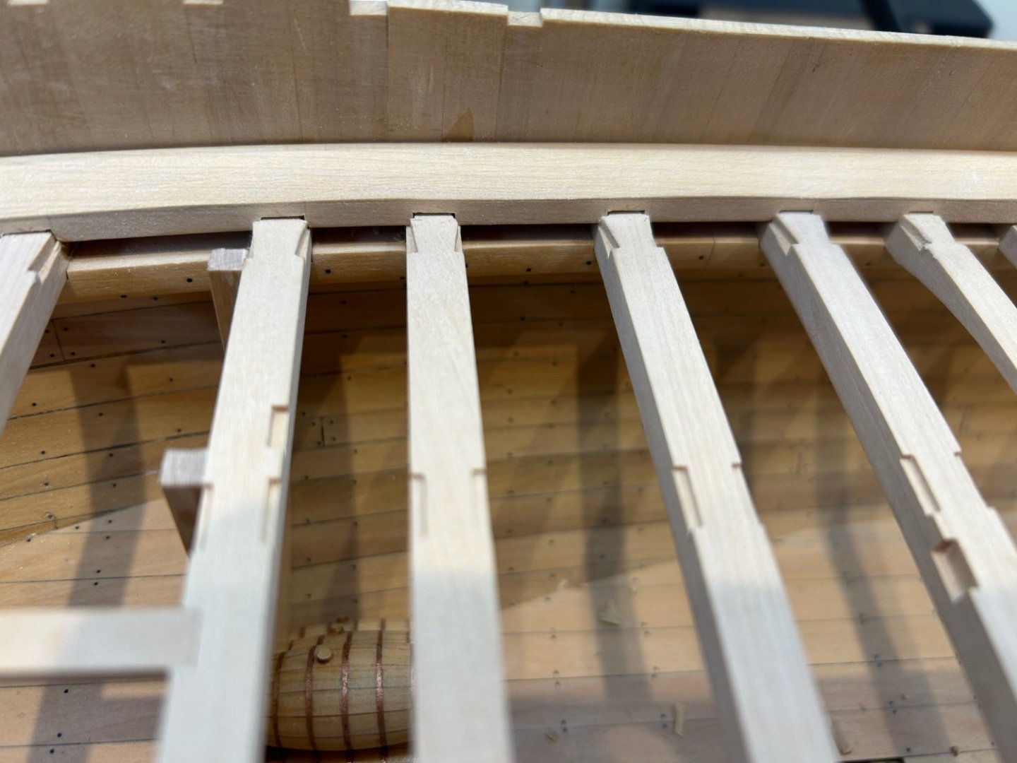
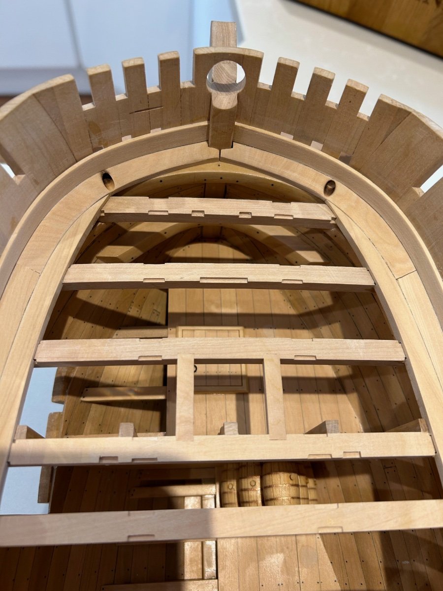
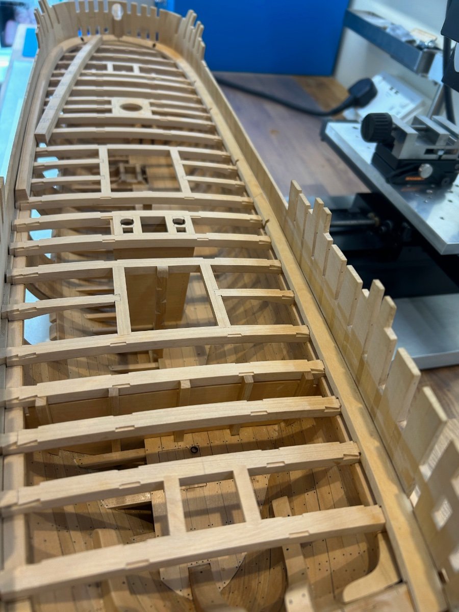
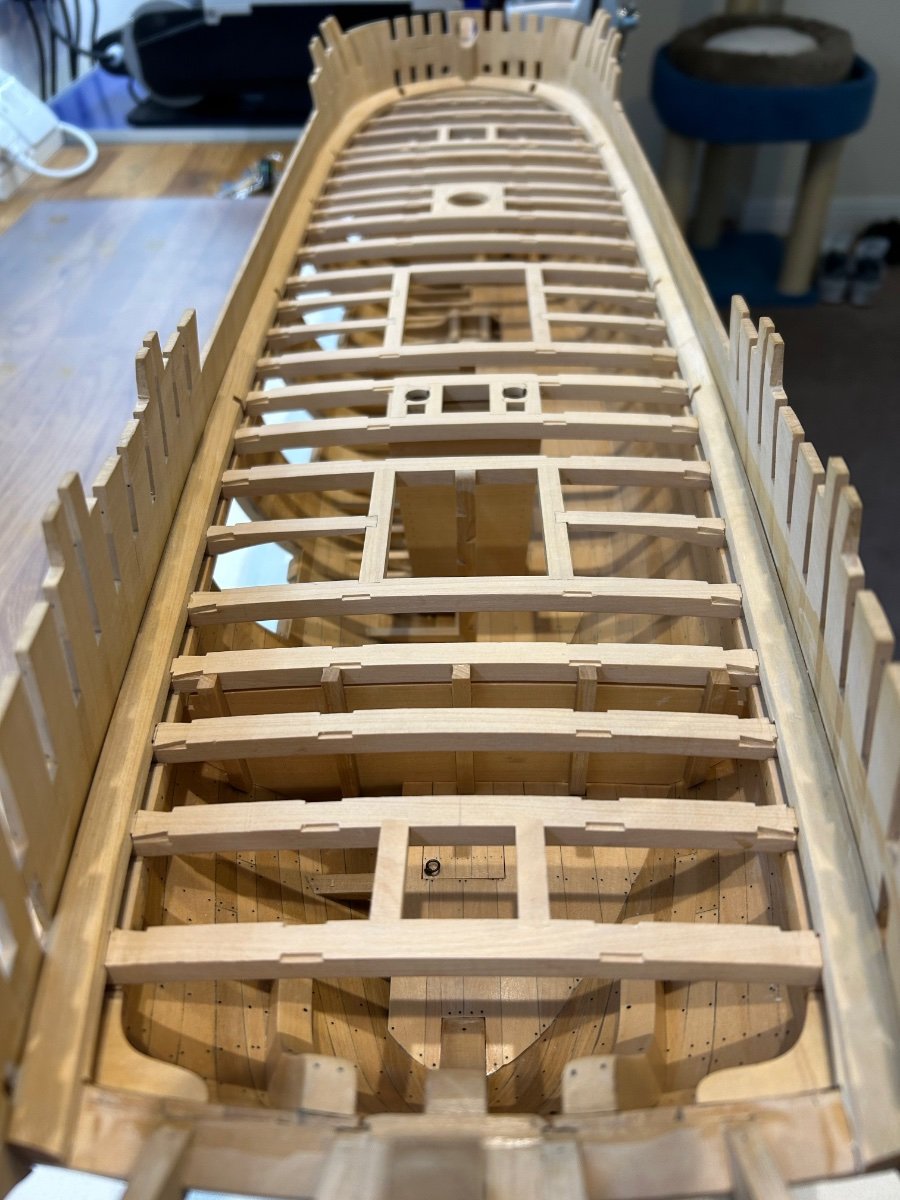
Next is where you can either make the job relatively easy or a bit more difficult. The binding strakes partially pass over the top of the deck hatch openings. I really wanted to maintain the integrity of "Width A" in the picture below to keep the strake uniform in thickness along is full length.
So to do this I had to scribe the strakes around these obstacles. So instead of just cutting straight joining slots I ended up with the complex joints below. Have no idea if this is how they should be made its just the way that I wanted to do it.
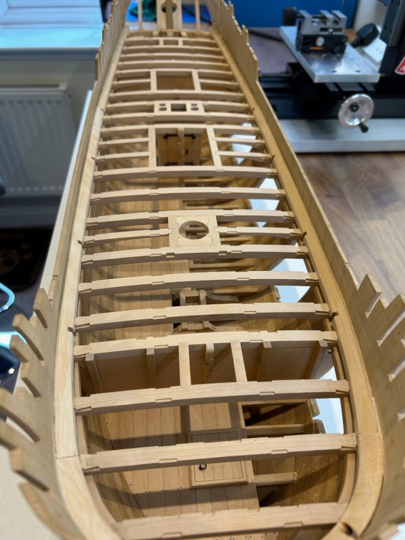
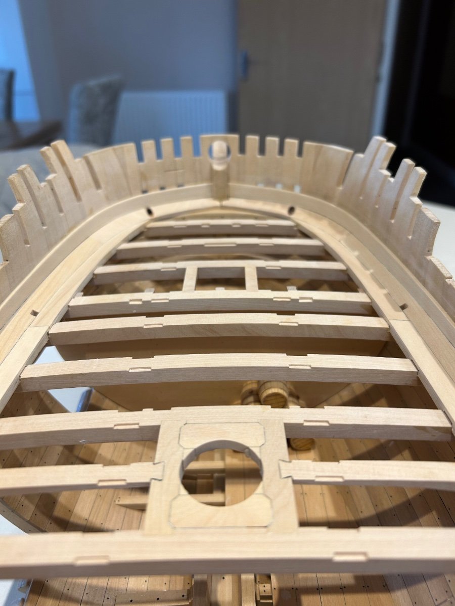
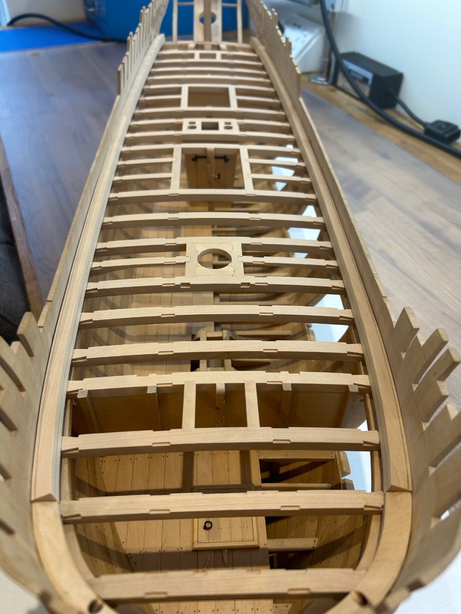
I did find that doing it this way once again made the fitting very easy as they locked into place and followed the curve of the deck so easily. I'm very happy with the results and I have also caught up at last with the required nailing. A few pictures below
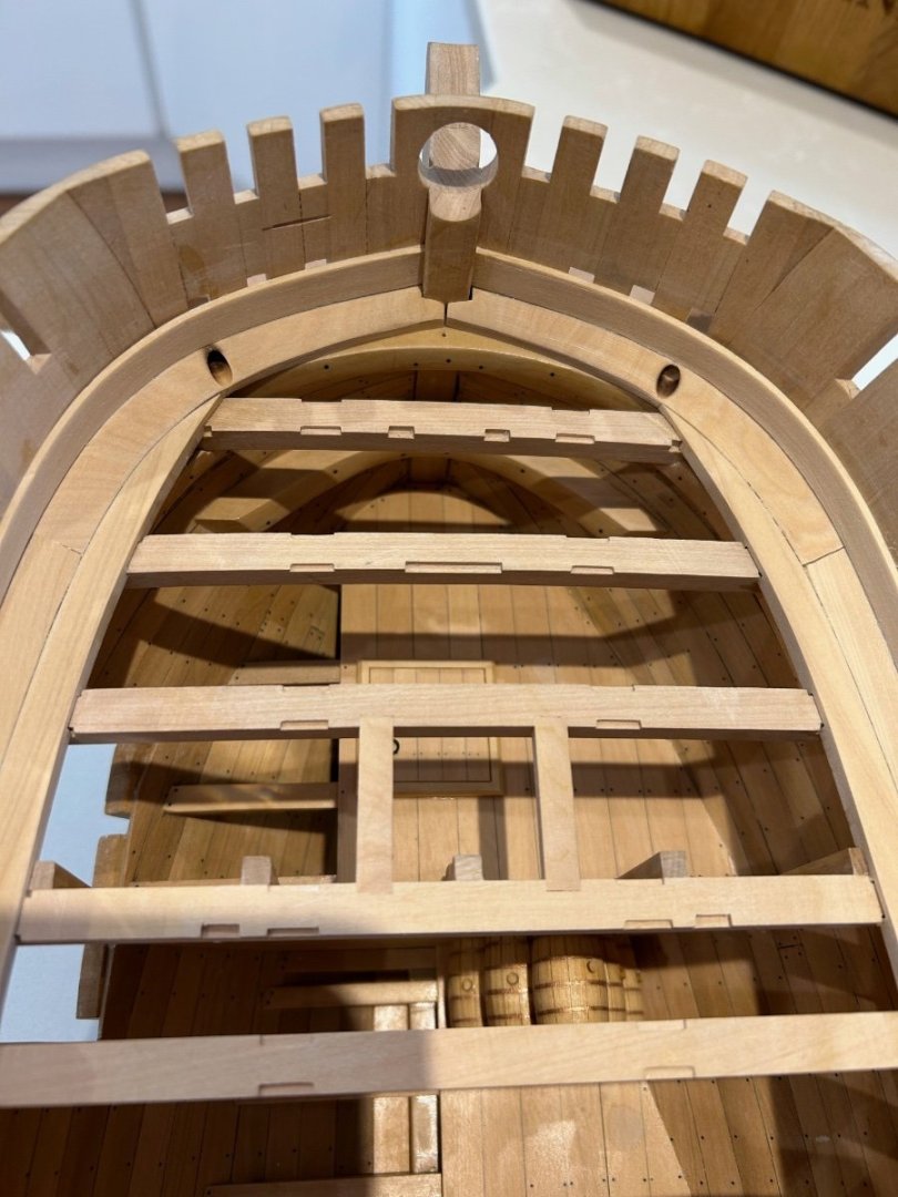
I'm very tempted now to leave the main deck as it is now? I understand that everything that needs to be placed on the deck will require lifting to the correct deck height but what are your thoughts on this? I have no experience of doing what I'm suggesting but I think that it would allow anyone that looks at the model to see the work carried out inside far better. Please let me know your thoughts.
So my next jobs are to make the bits, bowsprit partner, windlass supports and finish planking the inside of the bulwarks.
Thanks everyone - Mark